
IMAGE PROCESSING FRAMEWORK FOR FPGAS
Introducing a Plug-and-play Computer Vision Framework for Fast Integration
of Algorithms in Reconfigurable Hardware
Bennet Fischer and Raul Rojas
Intelligent Systems and Robotics, Free University of Berlin, Arnimallee 7, Berlin, Germany
Keywords:
Image Processing, FPGA, Framework, Signal Processing, Embedded.
Abstract:
This paper presents a framework for computer vision tasks on Field Programmable Gate Arrays (FPGA) which
allows rapid integration of vision algorithms by separating the framework from the vision algorithms. A vision
system can be created by using plug-and-play methodology. On an abstract level several input and output
channels of the system can be defined. Also, commonly used image transformations are modularized and can
be added to the inputs or outputs of an algorithm. Special input and output modules allow the integration of
algorithms with no knowledge of the surrounding framework.
1 INTRODUCTION
Two dimensional signal processing has ever since
been a demanding problem in computer science.
Computer vision as an application of the latter is still
a very active research area. With the steady improve-
ment of general computer hardware, many computer
vision algorithms are able to run in real time on com-
modity hardware. The importance of real time imple-
mentations is growing as computer vision is starting
to be employed in every day products like game con-
soles, mobile phones and driver assistance systems.
Most of these systems are by their nature embedded
systems. However, many of the fundamental algo-
rithms i.e. dense 3D reconstruction or optical flow
estimation are still not applicable to real time imple-
mentations. This applies to commodity pc hardware
and in particular to embedded processors.
Recently programmable graphics hardware gained
popularity in research for realizing real time imple-
mentations of demanding vision algorithms. This
type of hardware can be programmed in a familiar
way using the high level “C” language and thus re-
quires only a short training period for new users. The
level of hardware abstraction is comparable to CPU
programming. Memory access, input/output opera-
tions are all mapped to easy to use operations. This
makes graphics hardware attractive for quickly evalu-
ating algorithms. However, due to their high power
consumption they are not well suited to embedded
systems.
An established method of computational intensive
real time implementations is the use of field pro-
grammable gate arrays (FPGA) devices. FPGAs gen-
erally suite better to the needs of embedded systems
due to their lower power consumption (Jin et al.,
2009). This makes them attractive for appliances out-
side of the researchers laboratories i.e. in autonomous
systems. A detailed comparison of general purpose
processors (GPP), graphic processors (GPU) and FP-
GAs is given in (Cope et al., 2009). The main dis-
advantage of FPGA systems is, however, the high de-
velopment effort. New users are faced with a steep
learning curve. The time to the first productive use of
the device is usually long for two reasons:
• The user has to learn a new programming lan-
guage which describes hardware, not software.
Also the tool chain for implementing the written
programs is completely different to software tool
chains. High level synthesis tools trying to bring
the FPGA closer to the programming model of
traditional processors can help new users to de-
velop algorithms faster than before (BDTI, 2010).
However, these tools are in most cases not afford-
able for researchers or small companies.
• The hardware abstraction on FPGAs is poor, if not
absent. In the case of no abstraction, the periph-
eral hardware is simply wired to the input/output
(io) banks of the FPGA. All the higher levels of
abstraction have to be done by the user. One com-
mon concept of abstraction in the design of hard-
295
Fischer B. and Rojas R..
IMAGE PROCESSING FRAMEWORK FOR FPGAS - Introducing a Plug-and-play Computer Vision Framework for Fast Integration of Algorithms in
Reconfigurable Hardware.
DOI: 10.5220/0003801402950300
In Proceedings of the 2nd International Conference on Pervasive Embedded Computing and Communication Systems (PECCS-2012), pages 295-300
ISBN: 978-989-8565-00-6
Copyright
c
2012 SCITEPRESS (Science and Technology Publications, Lda.)

ware is the use of intellectual property (IP) cores.
Theses cores cover the underlying complexity of
hardware peripherals and offer a more abstract in-
terface to the functionality. Most FPGA vendors
offer IP cores for often used peripherals like Ran-
dom Access Memory (RAM) or networking hard-
ware. However, the interface to these cores is still
complex as they usually offer bus interfaces (PLB,
AXI, Whishbone, etc.). To access these kind of
cores, the user has to implement a bus participant,
thus needs to know the bus specification in detail.
This is a non trivial task and highly time consum-
ing.
In this paper we present a framework aimed at accel-
erating the development of FPGA vision algorithms.
The problems of FPGA development stated above, es-
pecial the latter one, are overcome by a high level
of peripheral hardware abstraction. This abstraction
specifically suits to the needs of computer vision al-
gorithms.
The typical use case of this framework is the cre-
ation of a real time capable prototype system. In con-
trast to GPU based real time prototypes, the imple-
mentation of the algorithms is much closer to a pro-
duction ready state. This allows the user to predict
the overall cost and energy consumption of the sys-
tem very precisely. It is assumed that the algorithms
are already evaluated using a non real time capable
implementation. This reference implementation can
then be ported to the FPGA and be deployed with lit-
tle effort. The user can concentrate on developing the
vision algorithms and is not forced to invest time in
retrieving and passing on the data.
The focus here is not to provide an overall high
level of abstraction covering also the vision algorithm
itself. Instead, the framework allows to test and use
production ready HDL implementations of algorithms
without any infrastructural developing overhead.
2 RELATED WORK
A FPGA co-processor framework is presented in
(Kalomiros and Lygouras, 2008). Several vision al-
gorithms are evaluated using a commercial Simulink
to HDL translator. Communication to the host PC is
done via USB and the data flow is organized by a soft
processor. As being a co-processing system with no
direct access to the image data, the latency is higher
than in a pre-processing system but the possible range
of applications is broader.
A framework for verification of vision algorithms
is presented in (van der Wal et al., 2006). Concep-
tual similar to the approach described by us, they use
image pipelines to process the data. However, due to
the crosspoint switch, their processing entities can be
connected at run-time, allowing high flexibility. This
flexibility is useful for hardwired Application Specific
Integrated Circuits (ASIC) which cannot be reconfig-
ured.
3 FUNDAMENTAL CONCEPTS
The framework itself consists of modules connected
by streams and a supervisor organizing the system
configuration and data flow. It is assumed that the
platform on which the framework is running consists
of at least an FPGA, an external RAM and a commu-
nication module to a workstation PC (gigabit ethernet,
PCI Express, etc.) all interconnected by the system
bus.
A module encapsulates an arbitrary function. In
the simplest form a module operates on data of the in-
put streams and delivers the result on one or several
output streams. More complex modules also interact,
besides the streams, with lower level components like
bus interfaces or hardware peripherals. However, to
the user this complexity is opaque as only the stream
interfaces are visible to him. Modules can be instanti-
ated and connected as hardware description language
(HDL) entities in source files or more convenient to
the user, via a graphical user interface (GUI) by drag-
ging them into the system to be built.
A stream is a unidirectional data flow interface.
The most common use of it is to transfer pixel val-
ues. Note that this interface is kept as simple as pos-
sible. The synchronization of this interface is only
word-wise. Every other synchronization information
has to be implicit which means that the data format of
a stream has to be known a priori. This is in general
true for image processing algorithms. The implicit
synchronization offers several advantages. First, due
to the fixed input format, the module can process the
data in a statically way. This eases the development
and normally speeds up the implementation. Second,
the module can trust the format of the input data. No
error checking has to be done on the format of the
input data. This leads to a better encapsulation of
functionality as an exceptional state will be handled
inside a module instead of being passed between two
modules. One prerequisite of this to work is that ev-
ery module delivers correctly synchronized data on its
output streams. In most cases this is easier to archive
than format error checking on the input streams in
case of explicit synchronization.
The supervisor is a general purpose soft proces-
sor with low speed requirements. It organizes the data
PECCS 2012 - International Conference on Pervasive and Embedded Computing and Communication Systems
296

flow from the FPGA system to the host application on
a data packet base. As the data packages are already
prepared by hardware components, the load of this
processor is low. Another task for the supervisor is
to initialize and configure the hardware modules. For
normal applications the user does not need to change
the software running on the processor. Drivers are
bound to specific modules and, if necessary, inserted
into the software automatically.
4 CORE MODULES
As stated above, the basic building block of the frame-
work is a module. The modules are grouped into three
categories:
• IO modules.
• Processing modules.
• Simulation/Debug modules.
4.1 IO Modules
4.1.1 Live Data Source
The live data source (LDSO) module offers a single
output stream from a hardware device. Typically it
delivers a pixel stream from a camera sensor.
4.1.2 Memory Data Source
The memory data source (MDSO) module takes data
from an external RAM device and transforms the data
to one or several output streams. It is connected to the
RAM controller via the system bus and to the super-
visor via a control interface. The bus interactions are
fully encapsulated by the module. By using this mod-
ule instead of the live data source as the algorithm
input, the system transforms from a pre-processor to
a co-processor. Image data can be delivered by the
workstation PC, processed by the system and sent
back.
4.1.3 Synchronized Data Source
The synchronized data source (SDSO) takes up to
three equally formatted input streams and synchro-
nizes them to pixel accuracy. The synchronized data
is then sent on three output streams. In case of no pos-
sible synchronization (due to buffer size restrictions)
the output channels are fed with pixels marked as in-
valid. This module is useful to transform loosely syn-
chronized camera sensor input to pixel synchronous
streams.
4.1.4 Memory Data Sink
The memory data sink (MDSI) is the counterpart to
the memory data source. To the user it provides a
single stream input, to the system a bus connection
and to the supervisor a control interface. The user
can send data to the module with a stream which will
be orderly written into the external RAM. The data
is packetized, addressed and sent via the system bus
into the frame buffers in RAM. Also, the supervisor is
informed when new data has arrived in memory. This
information can be used by the supervisor to transfer
the data to a workstation PC via gigabit ethernet or pci
express. Already available scatter-gather direct mem-
ory access (DMA) components allow the supervisor
to transfer the data with zero copy overhead.
4.2 Processing Modules
In the following section two examples of processing
modules are given. These modules are part of the
framework and can be used to compose more complex
functionalities out of them. Two examples of their us-
age will be showed later on.
4.2.1 Separable Convolution
The separable convolution (SC) realizes a 2D finite
response filter. Using this module many standard op-
erations can be performed by adapting the filter coef-
ficients. The coefficients can be configured at build
time.
4.2.2 Geometric Image Transformation
The geometric image transformation (GIT) module
takes a pixel stream and performs an arbitrary geo-
metric transformation on the image. The transforma-
tion function can be changed in the running system.
This function is usually used to remove lens distor-
tion or rectify sets of image streams.
4.3 Simulation/Debug Modules
4.3.1 Memory Data Source
The memory data source module can be re-purposed
as a debug module. By replacing a live data source
with it, the system can process artificial or static im-
ages.
4.3.2 File Data Source
The file data source (FDSO) is a non synthesizable
simulation module. It can be used as a test bench dur-
IMAGE PROCESSING FRAMEWORK FOR FPGAS - Introducing a Plug-and-play Computer Vision Framework for Fast
Integration of Algorithms in Reconfigurable Hardware
297
ing simulation to verify the functionality of a module.
The FDSO reads data from image files or comma sep-
arated files and transforms the data to a stream. This
stream can be connected to a module under test as the
input stimuli.
4.3.3 File Data Sink
As with the MDSO, the file data sink (FDSI) is the
counterpart of the FDSO. In a simulation the output
stream of a module under test can be connected to
the FDSI. The data received is written orderly into a
file, making it available for post-simulation verifica-
tion i.e. the check against a reference implementation.
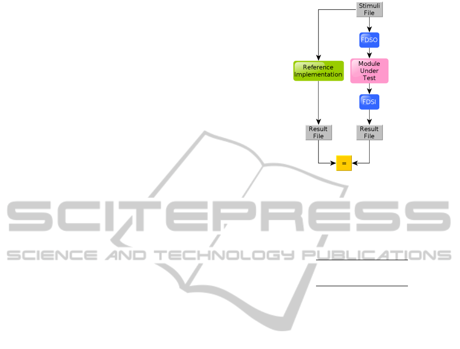
The module verification is visualized in figure 1.
5 EXAMPLE APPLICATIONS
The presented framework has been in use since one
year at the Free University of Berlin inside the au-
tonomous car “Made in Germany”.
Automotive image processing requires low la-
tency as well as low power consumption. These re-
quirements make the use of FPGA hardware attrac-
tive.
The image data is delivered by two CMOS cam-
eras mounted behind the windshield with 768x500
high dynamic range (HDR) images at 30 frames per
second. The processed data is sent to a laptop via gi-
gabit ethernet for higher level processing. This setup
frees the laptop from the highly time consuming low
level vision algorithms.
The data flow graphs illustrating the examples
consist of modules visualized as boxes and streams
visualized as arrows.
5.1 Module Verification
Before being uploaded to the hardware, modules need
to be verified. The framework supports verification
through the FDSO and FDSI modules. A basic veri-
fication setup is illustrated in figure 1. Both the refer-
ence implementation and the hardware implementa-
tion getting the same stimuli and write their results to
a comma separated file. If the hardware implementa-
tion is behaviorally correct, the two result files should
be identical.
5.2 Optical Flow
The first application example for the framework is
the estimation of the optical flow (Lucas and Kanade,
1981).
Figure 1: Module verification.
What follows is a brief overview of the Lucas-
Kanade algorithm:
As a first step, the spatial derivatives are calculated.
I
x
(x, y) =
I(x +1, y) − I(x − 1, y)
2
I
y
(x, y) =
I(x, y + 1) − I(x, y − 1)
2
Next, the Spatial gradient matrix G is determined
where w describes the size of an integration window.
This matrix is also called structure tensor.
G =
p
x
+w
x
∑
x=p
x
−w
x
p
y
+w
y
∑
y=p
y
−w
y
I
2
x
(x, y) I
x
(x, y)I
y
(x, y)
I
x
(x, y)I
y
(x, y) I
2
y
(x, y)
By using the temporal derivative δI and the spa-
tial derivatives I
x
, I
y
the image mismatch vector b is
calculated.
δI(x, y) = I(x, y) − J(x, y)
b =
p
x
+w
x
∑
x=p
x
−w
x
p
y
+w
y
∑
y=p
y
−w
y
δI(x, y)I
x
(x, y)
δI(x, y)I
y
(x, y)
The following equation then gives the estimate of
the optical flow η:
η = G
−1
b
The matrix G
−1
is also known as the covari-
ance matrix. The algorithm is explained in detail in
(Bouguet, 1999).
As a prefiltering step the image pyramid is created
and written into the external RAM. The module struc-
ture of the prefilter is shown in figure 2.
After the arrival of a frame from the prefilter, the
supervisor triggers the MDSO module seen in figure
3. The current frame I and the preceding frame J are
PECCS 2012 - International Conference on Pervasive and Embedded Computing and Communication Systems
298
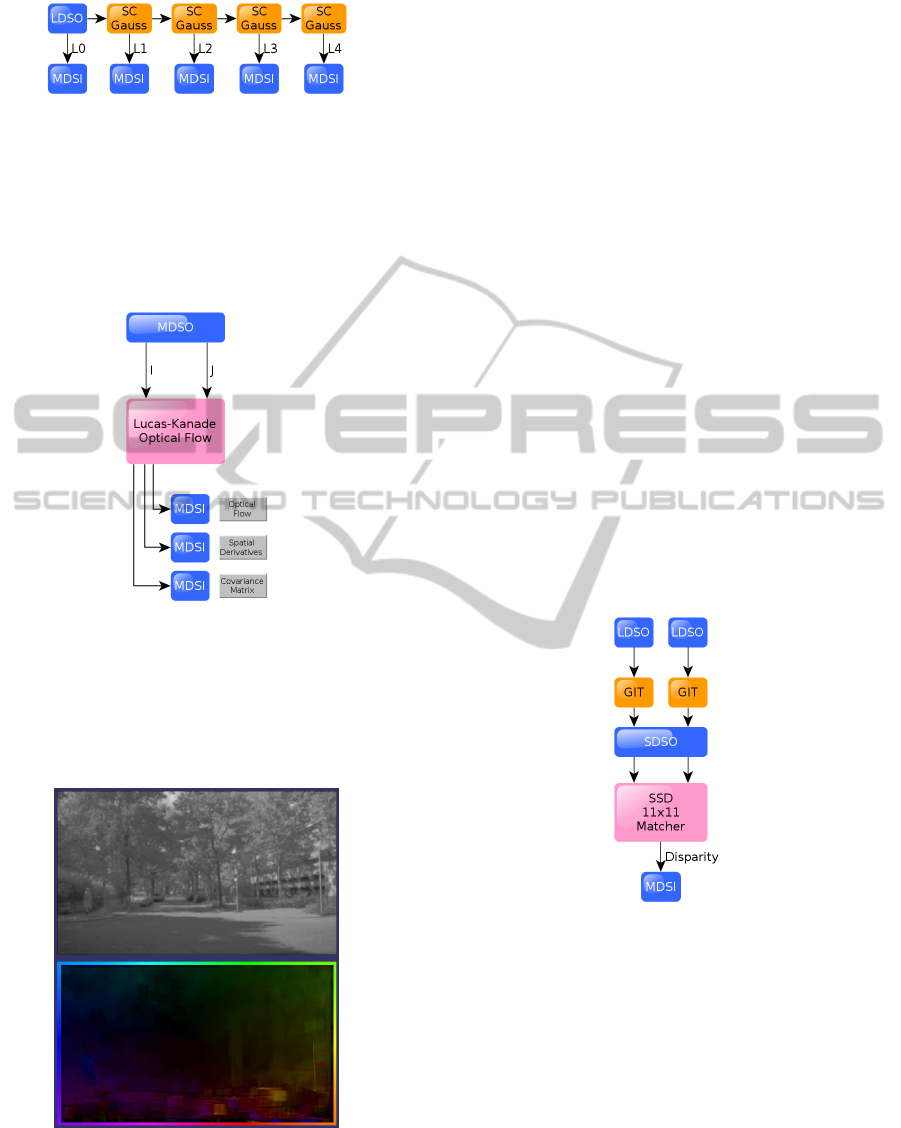
Figure 2: Preprocessing modules forming Gaussian pyra-
mid: A live image is low pass filtered four times by a
Gaussian kernel (SC). Each filter result is written to RAM
(MDSI).
simultaneously input into the optical flow estimator.
Note that the estimator has no other dependency to
the framework than its stream interfaces.
Figure 3: Lucas Kanade optical flow integration.
The visualized result of the optical flow estimator
can be seen in figure 4. The colors denote the direc-
tion and the intensity the speed of the flow. Reference
colors are found on the border of the image.
Figure 4: Top: Source image. Bottom: Optical flow result.
5.3 Stereo Vision
The second example for the framework is a module
for estimating the distance of objects by finding
corresponding image points in a stereo image pair.
As shown in figure 5 the geometric image transfor-
mation (GIT) module is used as a preprocessing step
to remove the lens distortion and rectify the images.
The transformed streams are then synchronized to
pixel accuracy by the SDSO module.
What follows is a brief description of the block
matching algorithm:
The cost C for the comparison of two blocks of
size w at the disparity d is defined by the sum of
squared differences.
C(x, y, d) =
p
x
+w
x
∑
x=p
x
−w
x
p
y
+w
y
∑
y=p
y
−w
y
(L(x, y) − R(x − d, y))
2
The disparity D with the lowest cost over the
search window D
max
is the estimate of the disparity.
C
min
(x, y) = min
0≤d≤D
max
C(x, y, d) = C(x, y, D)
Figure 5: Stereo vision integration: Two live images
(LDSO) being rectified (GIT) and synchronized (SDSO).
The streams are block matched and the disparity is written
to RAM (MSDI).
The result of the depth estimation on a street sce-
nario is visualized in figure 6. The color denotes the
disparity of the pixel. Occluded and low textured ar-
eas are filtered out with a left to right check and a con-
fidence check regarding the uniqueness of the mini-
mal cost. Also a sub-disparity interpolation is per-
formed, resulting in a ready to use disparity image.
IMAGE PROCESSING FRAMEWORK FOR FPGAS - Introducing a Plug-and-play Computer Vision Framework for Fast
Integration of Algorithms in Reconfigurable Hardware
299
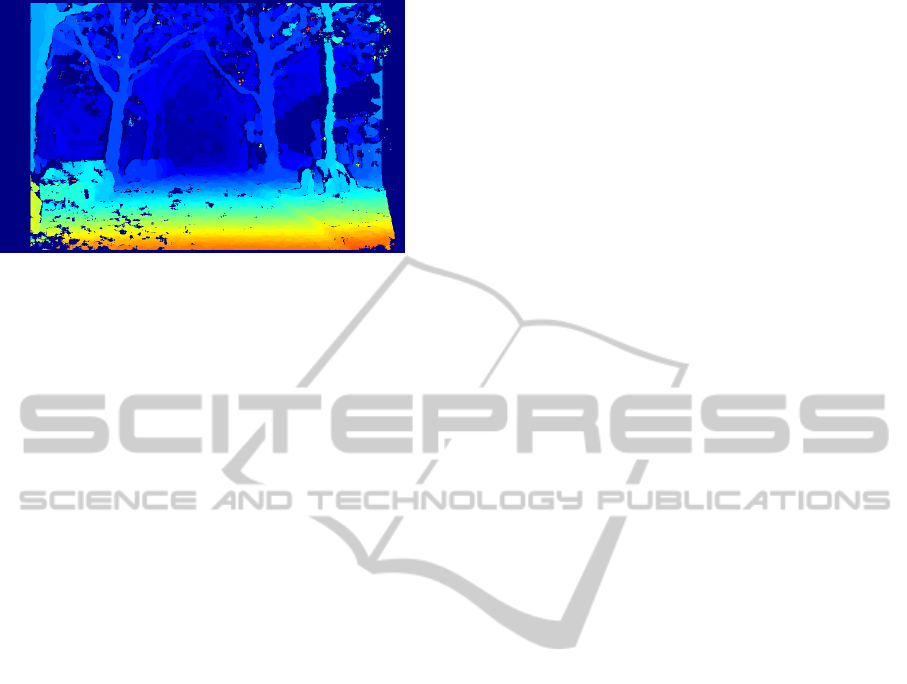
Figure 6: Stereo Vision result of a street scenario.
6 SUMMARY
In this paper we have presented a framework help-
ing researchers to quickly evaluate production ready
vision algorithms on FPGAs. The strict modulariza-
tion of functionality and small dependencies between
modules allow the user to quickly change the func-
tionality of the whole system. Functionalities can be
added or removed depending on the requirements of
the application and the available chip area.
The system proofed to fulfill the goal of fast al-
gorithm integration and reliable operation in the au-
tonomous car “Made in Germany”. Future devel-
opments will target on porting the upper level algo-
rithms interpreting the preprocessed data to an em-
bedded system. Examples for these algorithms are au-
tomatic camera calibration or obstacle avoidance cur-
rently running on a commodity laptop.
ACKNOWLEDGEMENTS
We would like to thank Robert Richter for his work
on implementing the Lucas-Kanade algorithm.
REFERENCES
BDTI (2010). The AutoESL Au-
toPilot High-Level Synthesis Tool.
http://www.bdti.com/MyBDTI/pubs/AutoPilot.pdf.
Bouguet, J. (1999). Pyramidal implementation of the lu-
cas kanade feature tracker description of the algo-
rithm. Intel Corporation, Microprocessor Research
Labs, OpenCV Documents, 3(2):1–9.
Cope, B., Cheung, P., Luk, W., and Howes, L. (2009). Per-
formance comparison of graphics processors to recon-
figurable logic: A case study. IEEE Transactions on
Computers, 59(4):433–448.
Jin, Q., Thomas, D., and Luk, W. (2009). Exploring
reconfigurable architectures for explicit finite differ-
ence option pricing models. In Field Programmable
Logic and Applications, 2009. FPL 2009. Interna-
tional Conference on, volume 54, pages 73–78. IEEE.
Kalomiros, J. and Lygouras, J. (2008). Design and eval-
uation of a hardware/software FPGA-based system
for fast image processing. Microprocessors and Mi-
crosystems, 32(2):95–106.
Lucas, B. and Kanade, T. (1981). An iterative image reg-
istration technique with an application to stereo vi-
sion. In Proceedings of the 7th International Joint
Conference on Artificial Intelligence (IJCAI), pages
674–679.
van der Wal, G., Brehm, F., Piacentino, M., Marakowitz,
J., Gudis, E., Sufi, A., and Montante, J. (2006). An
FPGA-based verification framework for real-time vi-
sion systems. Pattern Recognition, 2.
PECCS 2012 - International Conference on Pervasive and Embedded Computing and Communication Systems
300
