SALT WEATHERING OF BRICK WALLS
Salman Shahidi
CNRS, Orl´eans, France
Keywords:
Natural Phenomena, Weathering Phenomena, 3D Texture Synthesis, Displacement Mapping.
Abstract:
Human made buildings and constructions are very dependent upon various weathering phenomena, resulting
in complex appearances and patterns that vary with time and environment. Handling such complexity is
important in computer graphics in order to improve the realism of images. This difficult work is usually done
by hand by designers and can lead to non-plausible results. Another way to tackle this problem is to provide
new aging algorithms. Among a large number of weathering, salt weathering results in important visual
changes affecting widely used materials: bricks and mortars. In this paper, we present a method to generate the
texture of deformed and eroded masonry face by efflorescence. To avoid complex and unintuitive formulations
while keeping plausible results, we chose a physically-inspired model. Moreover, in order to keep an important
artistic control, it is possible for the user to create weathered textures in preferential masonry zones, leading to
a great variety of different patterns. First, we synthesize a masonry (brick/mortar) solid texture. Next, we add
the effects of efflorescence and sub-florescence using a specific algorithm accounting for regular crystallized
or eroded surface masonry by displacement mapping. In addition, to model very strong weathering effects on
building walls, we apply a simple geometry modification method to modify the surface before its rendering.
1 INTRODUCTION
Mortar and bricks are two important and widely used
construction materials. Their appearance is often
greatly affected by environmental and time depen-
dent phenomena such as salt deposition and crystal-
lization, which lead to their deterioration. therefore,
to make realistic images of human constructions, we
should take into account these imperfections to avoid
non-realistic smooth texture shown in usual synthe-
sized image. This issue is increasingly investigated in
computer graphics, using new techniques in all com-
puter graphics fields (modeling, rendering, animat-
ing). These works haveresulted in generic methods as
well as specialized techniques focusing on a specific
weathering process. Due to the visual importance of
brick and masonry in our environment, we propose to
treat this specific weathering phenomenon by a spe-
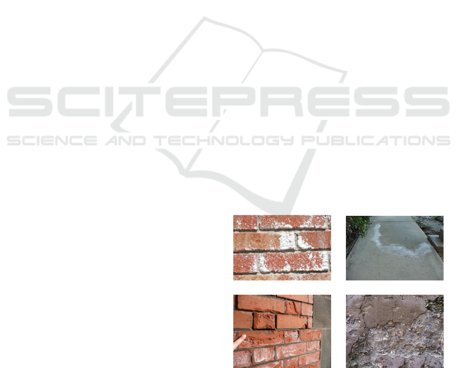
cialized technique. An image gallery of weathering
problem in the course of time and salts on the ma-
sonry is shown in Figure 1. The alterations are clearly
visible on the surfaces.
The goal of this work is to automatically generate
the most common weathering effects on brick con-
structions. We focus specifically on deformed crys-
tallized masonry and structural damage such as crum-
(a) (b)
(c) (d)
Figure 1: Examples of weathering effects. (a) Crystalliza-
tion on a brick wall. (b) Thin efflorescence on a homoge-
neously cement. (c) and (d) present damages dues to crys-
tallization that occurs inside the material near the surface.
bling and erosion. For this, we propose to use a
masonry surface model built upon solid texturing
(Peachey, 1985; Perlin, 1985). Solid texturing is
well suited for patterns as for efflorescence and ero-
sion on the masonry, which are intrinsically three-
dimensional.
7
Shahidi S..
SALT WEATHERING OF BRICK WALLS.
DOI: 10.5220/0003807600070015
In Proceedings of the International Conference on Computer Graphics Theory and Applications (GRAPP-2012), pages 7-15
ISBN: 978-989-8565-02-0
Copyright
c
2012 SCITEPRESS (Science and Technology Publications, Lda.)

Figure 2: Flowchart of the system. We adopt the solid tex-
ture method to synthesize a clean masonry. We make a dis-
crete 3D block B of colors of size N
3
. The block B is pro-
duced by extruding and perturbing an input 2D image patch,
representing a view of the desired 3D texture. To synthesize
masonry, we can apply the block of colors B to a masonry
silhouette.
The overall design of our system is organized ac-
cording to the flowchart shown in Figure 2. The first
task is to extract a patch from real photo. To ob-
tain a discrete 3D block B of size N
3
we extrude this
patch along its perpendicular direction to synthesize
the solid texture of a clean brick. In order to keep
the realistic texture, we simply perturb the extrusion
process by Perlin-noise (Perlin, 1984). Texturing a
brick shape mesh by solid texture B, results in a for-
mation of a clean brick without weathering effects.
By adding different forms and integrities of salt colors
on a clean brick, then using a specific surface degrada-
tion method, we can generate different efflorescence
and erosion patterns on masonry.
The next section gives a brief overview of the
previous and related work about surface deteriora-
tion synthesis, followed in section 3 by an overview
of the physics of salt crystallization leading to ma-
sonry surface damage. Section 4, deals with simulat-
ing of salt crystallization on the surface, then section
5 shows comparisons between real and synthesized
brick walls. Finally, in section 6 conclusions and fu-
ture work are given.
2 PREVIOUS AND RELATED
WORK
Becket and Badler handled imperfections of surface
by employing a fractal based texture synthesis tech-
nique (Becket and Badler, 1990). Blinn (Blinn, 1982)
and Hsu (Hsu and Wong, 1995) have studied dusty
surfaces, and Miller (Miller, 1994) has investigated
tarnished surfaces with accessibility shading algo-
rithms. Wong et al. have proposed a geometric
method to represent patinas, dust, and peeling (Wong
et al., 1997). Paquette et al. have proposed to han-
dle geometric defects due to impacts (Paquette et al.,
2001); they also investigated peeling and crackling of
paint (Paquette et al., 2002). Dorsey et al. (Dorsey
and Hanrahan, 1996) proposed a model to take into
account dirtiness brought onto surfaces by flow pro-
cesses, as well as weathered stones (Dorsey et al.,
1999). Merillou et al. have studied destructive cor-
rosion (Merillou et al., 2001). Bosch et al. (Bosch
et al., 2004) studied the scratches on surfaces. Des-
benoit et al. studied the growth of lichens (Desbenoit
et al., 2004).
Other techniques try to handle the weathering
phenomena in a more global way, often related to
measurements (Lu et al., 2007) or texture synthesis
(see for example (Cutler et al., 2002)). Note that
a survey on aging and weathering phenonema has
recently been proposed in (Merillou and Ghazanfar-
pour, 2008).
Concerning the aging of buildings only a few stud-
ies have been specifically proposed. In (Shahidi et al.,
2005), we have presented a model to synthesize thin
efflorescence on fired-clay bricks without account-
ing for larger scale efflorescence, and Merillou et al.
(Merillou et al., 2010) have studied the effects of at-
mospheric pollution. The present work belongs to this
specific topic, increasing the available building aging
techniques.
3 PHYSICS OF SALT
CRYSTALLIZATION
We limit our model to a physical deterioration whose
damaging effects are linked with wetting and drying
cycles on the front walls. Drying/wetting experiments
were performed on various types of fired-clay brick
by Pel et al. (Pel et al., 2004). In all drying experi-
ments, it was observed that the moisture profiles were
almost homogeneous, and within the time of these ex-
periments (i.e. up to 14 days), no receding drying
fronts were observed. Figure 3 shows a diagrammatic
representation of the drying process with one drying
side (valid for fired clay bricks and mortar) that sat-
urated with a salt solution. During the drying pro-
cess, moisture will be transferred onto the drying sur-
face. The transport of moisture for the one-side sur-
face drying problem in time t and position x from dry-
ing surface, can be described by a nonlinear equation
of diffusion (see also (Huinink et al., 2002; Pel et al.,
2004)):
∂θ
∂t
=
∂
∂x
h
D(θ)
∂θ
∂x
i
, where θ(m
3
m
−3
) presents
the volumetric liquid moisture content, D(θ)(m
2
s
−1
))
is the iso-thermal moisture diffusivity. During the
drying, the ions (e.g., Na ions of NaCl salt solution
source) are advected to the drying surface and the
salt concentration slowly increases to saturate. At this
GRAPP 2012 - International Conference on Computer Graphics Theory and Applications
8
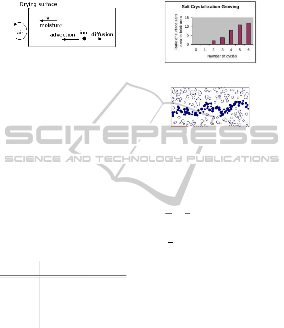
Figure 3: Diagrammatic representation of drying/wetting
process for the materials with one-side drying face. Illus-
tration adapted from work of Pel et al. (Pel et al., 2004).
point additional advection will result in crystallization
at the top of the sample (drying surface), which is ob-
served as a white efflorescence.
The wetting and drying cycles are the major cause
of crystallization that leads to masonry deterioration
(Bucea et al., 2005; Nehdi and Hayek, 2005). As
drying/evaporationoccur at the masonry surface, salts
crystallize out of solution producing the white crys-
tals known as efflorescence. These white crystals
can change color, reflection properties, and geome-
try of the surface. Hidden salt crystallization that
occurs below the masonry surface within the pores
is called sub-florescence, leading to often strong de-
terioration of the masonry. This may be visually
observed as cracking, spalling patterns, deflection,
stains, and erosion. Table 1 shows an observation of
these attacks by different salts (normally sodium sul-
phate and sodium chloride) in laboratory conditions
after 3 and 48 months, which is representative of real
conditions in long periods (Hees and Brocken, 2004).
Table 1: Overview of damages after 3 months and 48
months (tested by Hees and Brocken (Hees and Brocken,
2004)).
Sodium Sul-
phate
Sodium Chlo-
ride
3 months efflorescence,
delamination,
crumbling
efflorescence
48 months efflorescence,
push out, de-
lamination,
crumbling
efflorescence,
crumbling, slit
crack
Crystallization on brick wall accumulates with re-
peated wetting and drying cycles of the brick (Be-
navente et al., 2004; Pel et al., 2003; Matsuo and
Tanaka, 2004). Figure 4 shows the ratio of covered
salt area to total brick surface (Benavente et al., 2004)
against to the numbers of the drying/wetting cycles
(time).
Experiments performed on mechanism of efflores-
Figure 4: Diagram of salt crystallization growing.
Figure 5: Efflorescence pathway inside the masonry.
cence (Benavente et al., 2004; Pel et al., 2003; Hees
and Brocken, 2004) reveal that salt profile for the ho-
mogenous pore distributed brick can be as Figure 5.
This Figure shows that the salt paths growing within
this type of bricks are almost randomly flat after the
drying/wetting cycles.
Crystallization pressure was first formulated by
Correns (Correns, 1949) as follows:
P =
RT
V
s
× ln
C
C
s
In this equation, P is the pressure exerted by grow-
ing crystals in atm, R is the gas constant, T is the tem-
perature in Kelvin,V
s
is the molar volume of the solid
salt, and
C
C
s
is the degree of salt super saturation. As
our model is limited to physical deteriorations (not
chemical), for each point of masonry, we let us pro-
pose to calculate the parameter of pressure P accord-
ing to the density of crystallization around that point
(see section 4.3).
4 AGING SIMULATION
To obtain an efflorescence pattern, first we adopt a
solid texturing method to synthesize a clean masonry.
We make a discrete 3D block B of colors of size N
3
voxels (N is the input texture size). The block B is
produced by extruding and perturbing an input 2D
image patch that represents a view of the desired 3D
texture. To synthesize masonry, we apply the block of
colors B to a masonry silhouette. To add efflorescence
we use a potential number N
p
and active number N
d
of crystal departure points. N
p
and N
d
physically de-
pend on the porosity p of the material. Table 2 shows
SALT WEATHERING OF BRICK WALLS
9
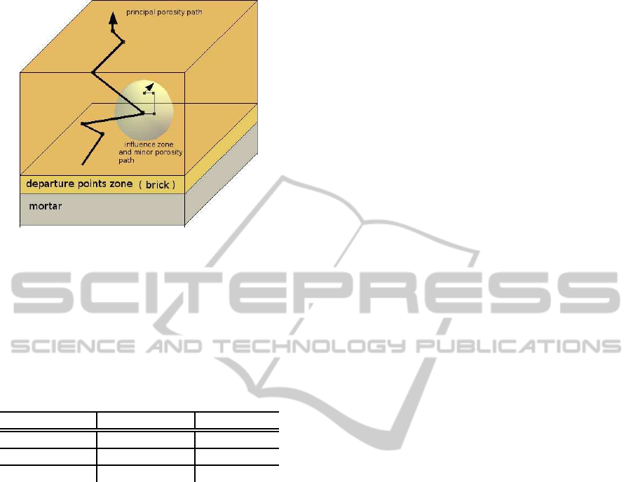
Figure 6: Efflorescence simulation. Starting points that tra-
verse principal porosity path are selected in the preferential
zone. Influence zone is used to pore interconnecting.
the density and porosity of the representative type of
materials. Generally, porosity of pointing mortar is
greater than clay brick porosity.
Table 2: Some characteristics of the masonries. Courtesy
from Hees and Brocken (Hees and Brocken, 2004).
Density(kg/m
3
) Porosity(v%)
Clay brick 1830 32
Pointing mortar 1670 37
Bedding mortar 2000 24
We assume homogenous porosity 35 percent for
the bricks and mortars (by information given for ex-
ample in (Pel et al., 1995; Hees and Brocken, 2004)),
however user can set it if needed. User can define
the starting points zone thickness for the brick; how-
ever, this thickness L
d
is controlled by system to avoid
the problematic errors of limitations and to have the
amount of porosity path linked to the brick surface
(known as open porosity). Starting points can be:
• Selected by user in preferential zones to generate
different textures, permitting to provide control of
the final results.
• Automatically chosen in the neighborhood of the
mortar because mortar acts as the source of salt,
penetrating in the brick (Hees and Brocken, 2004;
Matsuo and Tanaka, 2004). The starting points
for the mortar are distributed all over the mortar
volume, because of the homogenous distribution
of the salt in the mortar (Figure 6 ). The user can
select the type of material and texture (brick or
mortar) using the system interface.
Starting points depend on other environmental pa-
rameters such as salts present in outside of brick sur-
face and it is difficult to take into account all the pa-
rameters. We propose to choose the number of start-
ing points N
p
(or N
d
) as a function of the amount of
porosity inside the masonry and the position of each
starting point is selected randomly, in the preferential
zones. Thus, N
p
can be calculated by following equa-
tion:
N
p
= N × N × L
d
× p, 0 ≤ L
d
≤ N
By default, L
d
is 5 percent of the brick and whole
of the mortar volume size. The active starting points
to synthesis a block of color B is:
N
d
= N
p
× k, 0.0 ≤ k ≤ 1.0
Where k is a scale factor that can also repre-
sent the concentration of ions (salt solution viscosity).
User sets this parameter empirically (valid between
0.0 and 1.0) in order to obtain the desired results.
4.1 Salts Propagation
Efflorescence pathway is random inside the masonry
porous structure composed by T
p
steps (see section
3). A simple porous structure may be described as
the holes connected by the paths (Benavente et al.,
2004). These holes and paths are dilated or expanded
by the deposited salts. Physically T
p
represents ef-
florescence time quantification in one wetting/drying
period. Time quantifying is very difficult as efflores-
cence has very different diffusion time for each ma-
sonry type and for each environment (Ahl, 2003). In
addition, many other parameters play a role in salt
crystallization on the materials like as thermal con-
ditions. Therefore, in order to handle the time quan-
tification we try just to get the plausible graphical re-
sults. At each step of T
p
, coloring a voxel as crystal
element can grow crystallization to the masonry (mor-
tar/brick). To have the continuity of crystallization
effect as it is in masonry porous structure, we select
some spherical influence zones (randomly selected)
for each principal pathway (Figure 6 ). On each influ-
ence zone, we have the number N
s
of random propa-
gation directions in P
s
steps. N
s
value as well as N
p
(or N
d
) is related to porosity of masonry. In addition,
we consider another parameter N
c
, to handle repeated
wetting and drying cycles of the masonry. One can
control the quantity of salt inside the masonry by re-
peating T
p
in N
c
cycles.
As we have 26 neighbors for each propagation
step voxel, we can choose 10 new sub-propagation
directions in influence zone for the fired-clay brick
against to its porosity about of 35% ( 26×0.35 ≈ 10).
Influence zone diameter P
s
can be limited by oc-
clusion of air in dead-end pores. Having usual poros-
ity distribution between 0.1 and 10 microns (Dorsey
GRAPP 2012 - International Conference on Computer Graphics Theory and Applications
10
et al., 1999) that is varied with a factor of 100, we
consider P
s
=
T
p
100
to keep our model phenomenolog-
ical. Many porosity path and sub-propagation direc-
tions for each step can result in considerable crossing
between colored neighborhood points inside the ma-
sonry. Table 3 summarize all of these parameters.
4.2 Altering Surface Masonry by
Efflorescence
To attain a high quality surface alteration we use
an adaptive tessellation method of displacement map
(Doggett and Hirche, 2000). In this method, displace-
ment features are corresponded to the texture used as
the displacement map. These displacement features
are used to tessellate the base surface. The adaptive
tessellation produces fewer triangles than the methods
use uniform subdivision of the base surface. We de-
fine a positive displacement as the elevation and neg-
ative displacement as depression. Displacement off-
set correspond to the grey level colors from black to
white (neutral grey means no displacement).
To have an elevated surface attacked by salt crys-
tals we adopt the grey level image of each masonry
view as a positive displacement map. In addition,
to control the height of the displacement we define
a scale factor H
d
valid in the range [0, 1]. Figure 7
compares a real and two synthesized aged bricks us-
ing usual bump and displacement map methods.
4.3 Masonry Surface Erosion (Spalling)
The depth of damage generally depends on the brick
quality, crystallization, drying/wetting cycles, quan-
tity of masonry porosity and water suction. Because
of the model limitations that is not completely volu-
metric i.e., our model is based on mesh grid of the ob-
ject, we do not haveall the informationof the zone un-
derneath affected by sub-florescence. Then, we can-
not have a complete quantification of damage. How-
ever, we know that efflorescence can be an advanced
sub-florescence moved toward the surface by open
porosity. Therefore, we can define a function f to
compute the quantity (depth) of damage over the parts
of masonry that have been attacked by efflorescence:
D = f(P,H)
Here P is the pressure exerted by growing crystals;
H is the distance of underneath point from the exte-
rior surface. We assume that enough high crystal den-
sity can produce pressure enough to alter the image of
point along the normal vector to the surface. This as-
sumption is valid for the aged masonry (Bucea et al.,
2005; Nehdi and Hayek, 2005). So at each point of
masonry the density of salt crystallization can present
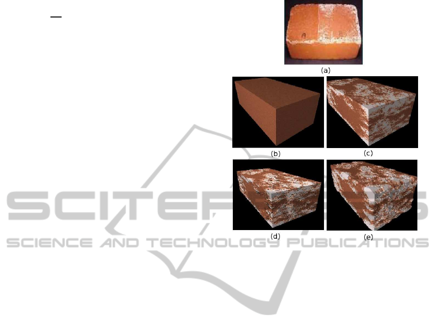
Figure 7: (a) A real brick efflorescence. (b) A synthesized
clean brick, (c) The brick affected by efflorescence without
change of geometry. (d) Bump mapping method to alter the
surface. (e) Displacement map method to alter the surface.
Here: N = 128, p = 0.3, N
s
= 8(26× p), N
c
= 10, L
d
= 2,
N
p
= (N × N) × p× L
d
= 9830, k = 0.03, N
d
= 294, T
p
=
300, P
s
= 3(T
p
/100), H
d
= 0.2. Note that brick in image
(d) has artifacts in its border.
its exerted pressure. Then, to calculate the parameter
P at each point, we can calculate the density of crys-
tallization around this point. The depth of damage is
depending on the H, i.e., higher value of H(H ≈ 1.0)
can damage the surface deeply over time. Note that
we consider all the crystallization grain, underneath
near enough the exterior face to have a regular alter-
ation. Function f has a direct relation with P and
H : P × H or (P × H)/c for example, where c is a
scale factor.
To synthesize a crumbled surface, we apply the
method presented in section 4.2 but with some differ-
ences. Here, we use a Negative displacement map to
alter the surface masonry. In addition, efflorescence
texture assignment can be chosen by user tact. This
is because on a masonry surface the efflorescence can
be absent or different from those on eroded areas.
Figure 8(b) represents a synthesized eroded brick.
4.4 Problem of Very Hard Alteration
To handle the very hard alteration of masonry facade
(Figure 9) we propose to alter the masonry mesh be-
fore its rendering.
SALT WEATHERING OF BRICK WALLS
11
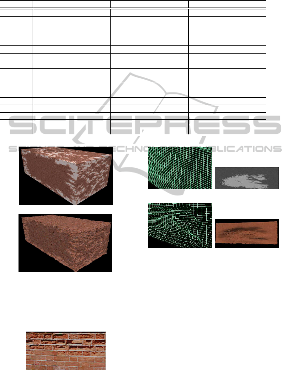
Table 3: Summary of efflorescence simulation parameters.
Parameter Description Range Value Phenomenological Meaning
N solid texture size masonry image size (pixel) -
p porosity of the masonry typically between 0.24 and
0.40
porosity
k scale factor of departure
points
between 0.0 et 1.0 viscosity scaling
N
p
potential departure points between 0 and N
3
× p water soluble penetrating
N
d
active number of departure
points
between 0 et N
3
× p× k solution viscosity
T
p
principle propagation walks graphical result (between 0
and N
3
)
drying/wetting cycles
N
s
number of random direc-
tions
26× p ( by default 10) influence zone driven
P
s
sub-propagation walks T
p
/100 pore interconnection
H
d
efflorescence depth between 0.0 and 1.0 damage scaling
N
c
number of cycles N
c
≥ 1 repeating T
p
L
d
departure points zone 0 ≤ L
d
≤ N for brick,
L
d
= N for mortar
mortar humidity thickness
(a)
(b)
Figure 8: (a) A synthesized efflorescence brick without al-
teration (b) An eroded synthesized brick ; to obtain this
eroded clay brick we use a negative displacement map with
eliminating the efflorescence color. The weathering param-
eters are as well as Figure 7. Damage depth D = f(P, H) =
P× H.
Figure 9: An example of very strong surface alteration.
(a) A brick mesh subdivi-
sion.
(b) A texture model.
(c) Deforming the mesh. (d) Rendering result.
Figure 10: Mesh alteration processes. Here to further visi-
bility the brick mesh is too subdivided, in practice 15×15×
15 subdivision is sufficient.
First task is to subdivide base mesh model just
enough high to the some cubical parts (for example
15× 15× 15 cubes for each brick). Then to have a de-
formation effect, we simply use an efflorescence tex-
ture corresponding to the displacement offset desired
(Figure 10). After these processes we have the de-
formed masonry to which one can apply the method
presented in the preceding section ( 4.3) to carry out
very strong crumbling. Here, texture used for geom-
etry deformation is the same one as the texture used
for displacement map.
GRAPP 2012 - International Conference on Computer Graphics Theory and Applications
12
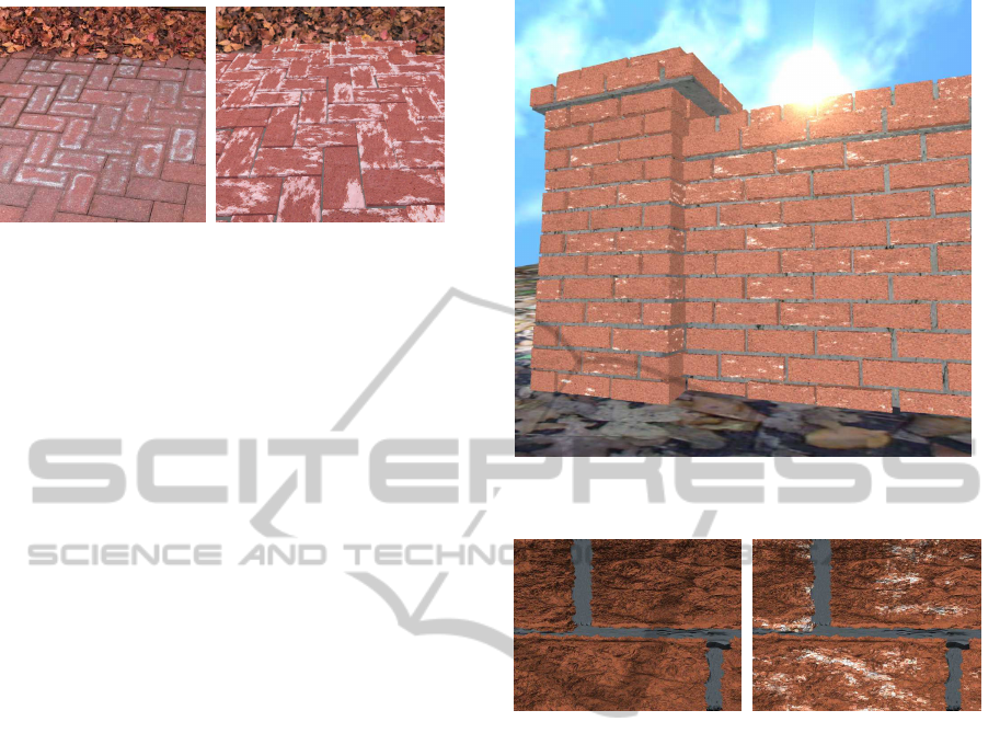
(a) (b)
Figure 11: (a) A real stone-pavement image. (b) Synthe-
sized image.
5 RESULTS
We were interested to generate wide variety of salts
decay aging of bricks. Aliasing artifacts are the com-
mon problem of textures that are present unfortu-
nately also for solid textures. In order to improve im-
age quality we integrate an antialiasing filtering pro-
cess in the system. There are generally two methods
of doing antialiasing, super-sampling, and edge anti-
aliasing. Super-sampling antialiasing method renders
the scene in a much high resolution and then scale
down to the original size. This way, the scene will
be approximated and the staircase edges will disap-
pear. This method is simple but requires an accelera-
tor of very high fill-rate. Edge antialiasing calculates
all edges and their surrounding polygons to find out
the best color for the edge pixels. This calculation is
highly CPU-intensive and is rarely done in consumer-
level 3D accelerators. As the system presented in this
paper is not restricted to real-time rendering, i.e., tex-
ture synthesis computation time is less than one sec-
ond and synthesis time for a construction with 1000
bricks using an Intel DUO 3.0 GHZ is about 15 min-
utes (with N = 64), this gives us the freedom to use
edge antialiasing method.
Figure 11 illustrates a comparison of a real stone-
pavement image and synthesized one. Each brick be-
haves independently, depending on numerous param-
eters. Figure 12 illustrates a synthesized landscape
by different degree of efflorescence and erosion. To
generate such virtual construction, user can instanti-
ate each brick and define its position, then he can tex-
ture it by a great variety of solid texture. Two exam-
ples of very hard erosion on brick walls are shown in
Figure 13.
Figure 12: Synthesized landscape.
Figure 13: Very hard brick surface erosion.
6 CONCLUSIONS AND FUTURE
WORK
This paper presents improvements and solutions to
the issues unsolved in former work (Shahidi et al.,
2005). We have used the same 3D texture model to
synthesize efflorescence color on masonry, by adding
other different visual aspects as geometry modifica-
tion and mechanical damage. The method is physi-
cally inspired and is simple to implement as it is based
on well-known solid texture and displacement map.
Furthermore, the system providesa good computation
time (Table 4). While the results are plausible and can
cover common weathering phenomena, we feel there
are several possibilities for future work. An important
future work is to generate the 3D texture in a narrow
region around the boundary of the solid texture. This
improvement not only can speed up the calculation
process of texture synthesis, but also can decrease the
memory requirements.
Another possible improvement is to sculpt the fa-
cade of construction. We handled it by a geometri-
SALT WEATHERING OF BRICK WALLS
13

Table 4: A representative table of times (in minute)
for rendering some results. Note that for all particles
(brick/mortar) in these figures we have the unique initial
subdivision mesh (equal triangle number).
- N
3
Particle number Time
Figure 11 128
3
237 31
Figure 12 128
3
226 30
cal model before rendering the object. However, we
believe using a volumetric model is preferred, as it
can directly perturb the surface without need to fur-
ther texturing process. In addition, by the volumet-
ric modeling other weathering phenomena as the salts
present very dens on the surface, crack, etc. will be
easier to handle; hence, in future we envisage work-
ing on it.
Our current implementation allows the user man-
ually position and texture each brick separately, we
can improve this system to automatic positioning and
add the weathering aspect according to wall location.
For this, one can use the environment parameters as
humidity, salt degree, porosity, etc.
We have assumed that the masonry has a homoge-
neous structure, however it is not common and there
are inhomogeneous aspects inside the masonry that
can change weathering effects. This problem should
be considered.
REFERENCES
Ahl, J. (2003). Salt diffusion in brick structures. In Journal
of Materials Science, volume 38, pages 2055–2061.
Becket, W. and Badler, N. (1990). Imperfection for realis-
tic image synthesis. In Journal of Visualization and
Computer Animation, volume 1, pages 26–32.
Benavente, D., Garcia, M., Garcia-Guinea, J., Sanchez-
Moral, S., and Ordonez, S. (2004). Role of pore struc-
ture in salt crystallisation in unsaturated porous stone.
In Journal of Crystal Growth, volume 260, pages 532–
544.
Blinn, J. F. (1982). Light reflection functions for simulation
of clouds and dusty surfaces. In Computer Graphics,
volume 3, pages 21–29.
Bosch, C., Merillou, S., Pueyo, X., and Ghazanfarpour, D.
(2004). A physically-based model for rendering re-
alistic scratches. In Computer Graphics Forum, vol-
ume 23, pages 361–370.
Bucea, L., Khatri, R., and Sirivivatnanon, V. (2005). Chem-
ical and physical attack of salts on concrete. In Pro-
ceedings Urban Salt 2005 Conference.
Correns, C. (1949). Growth and dissolution of crystals un-
der linear pressure. In Discussions of the Faraday So-
ciety, volume 5, pages 267–71.
Cutler, B., Dorsey, J., McMillan, L., Muller, M., and Jag-
now, R. (2002). A procedural approach to author-
ing solid models. In ACM Transaction on Graphics
(TOG), volume 21, pages 302–311.
Desbenoit, B., Galin, E., and Akkouche, S. (2004). Simulat-
ing and modeling lichen growth. In Computer Graph-
ics Forum, volume 23, pages 361–370.
Doggett, M. and Hirche, J. (2000). Adaptive view de-
pendent tessellation of displacement maps. In SIG-
GRAPH/Eurographics Workshop on Graphics Hard-
ware, pages 59–66.
Dorsey, J., Edelman, A., Jensen, H., Legakis, J., and Peder-
sen, H. (1999). Modeling and rendering of weathered
stone. In ACM SIGGRAPH, pages 225–234.
Dorsey, J. and Hanrahan, P. (1996). Flow and changes in
appearance. In ACM SIGGRAPH, pages 411–420.
Hees, R. and Brocken, H. (2004). Damage development
to treated brick masonry in a long-term salt crystalli-
sation test. In Construction and Building Materials,
volume 18, pages 331–338.
Hsu, S. and Wong, T. (1995). Simulating dust accumula-
tion. In IEEE Computer Graphics and Applications,
volume 15, pages 18–22.
Huinink, H., Pel, L., and Michels, M. (2002). How ions
distribute in a drying porous medium-a simple model.
In Phys Fluids, volume 14, pages 1389 –1395.
Lu, J., Georghiades, A., Glaser, A., Wu, H., Wei, L.-
Y., Guo, B., Dorsey, J., and Rushmeier, H. (2007).
Context-aware textures. In ACM Trans. Graph., vol-
ume 26, pages 167–174.
Matsuo, T. and Tanaka, K. (2004). Mechanism of efflores-
cence on historical brick masonry buildings reinforced
with concrete. In Proceedings of 10th International
Conference on Durability of Building Materials and
Components, pages 1–8.
Merillou, N., Merillou, S., Ghazanfarpour, D., Dischler, J.,
and Galin, E. (2010). Simulating atmospheric pollu-
tion weathering on buildings. In WSCG, pages 65–72.
Merillou, S., Dischler, J.-M., and Ghazanfarpour, D. (2001).
Corrosion: Simulating and rendering. In Graphics In-
terface, pages 167–174.
Merillou, S. and Ghazanfarpour, D. (2008). A survey of ag-
ing and weathering phenomena in computer graphics.
In Computer Graphics, volume 32, pages 159–174.
Miller, G. (1994). Efficient algorithms for local and global
accessibility shading. In ACM SIGGRAPH, vol-
ume 21, pages 319–326.
Nehdi, M. and Hayek, M. (2005). Behavior of blended ce-
ment mortars exposed to sulfate solutions cycling in
relative humidity. In Cement and Concrete Research,
volume 35, pages 731–742.
Paquette, E., Poulin, P., and Drettakis, G. (2001). Surface
aging by impacts. In Graphics Interface, pages 175–
182.
Paquette, E., Poulin, P., and Drettakis, G. (2002). The sim-
ulation of paint cracking and peeling. In Graphics In-
terface, pages 59–68.
Peachey, D. R. (1985). Solid texturing of complex surface.
In Computer Graphics, pages 279–286.
GRAPP 2012 - International Conference on Computer Graphics Theory and Applications
14

Pel, L., Huinink, H., and K.Kopinga (2003). Salt transport
and crystallization in porous building materials. In
Magnetic Resonance Imaging, volume 21, pages 317–
320.
Pel, L., Huinink, H., Kopinga, K., van Hees, R., and Adan,
O. (2004). Efflorescence pathway diagram: under-
standing salt weathering. In Construction and Build-
ing Materials, volume 18, pages 309–313.
Pel, L., Kopinga, K., Bertram, G., and Lang, G. (1995).
Water absorption in fired-clay brick observed by nmr
scanning. In J. Phys. D: Appl. Phys., volume 28, pages
675–680.
Perlin, K. (1984). A unified texture/reflectance model.
In SIGGRAPH 84 Advanced Image Synthesis course
notes.
Perlin, K. (1985). An image synthesizer. In Computer
Graphics, volume 19, pages 287–296.
Shahidi, S., Merillou, S., and Ghaznanfarpour, D. (2005).
Phenomenological simulation of efflorescence in
brick constructions. In Proceedings of Eurographics
on Natural Phenomena, volume aug, pages 17–23.
Wong, T., Ng, W. Y., and Heng, P. A. (1997). A geometry
dependent texture generation framework for simulat-
ing surface imperfections. In Proceedings of Euro-
graphics Workshop on Rendering, pages 139–150.
SALT WEATHERING OF BRICK WALLS
15
