SEMI-AUTOMATIC FLOOR-PLAN RECONSTRUCTION
FROM A 360
O
PANORAMIC IMAGE
Alexander Tarnavsky, Alexander Yusupov and Dmitry Rudoy
Technion, Israel Institute of Technology, Haifa, Israel
Keywords: 360
o
Panorama, Indoor 3d Reconstruction, Floor-plan.
Abstract: The ease of panorama creation has made it very popular. Although it is a very convenient way to convey the
environment, panoramic images can often be confusing. This discomfort has major influence in a 360
degree indoor panorama, where the viewer is forced to look in all the directions at the same time. In this
paper we propose an alternative approach for visualization of the indoor environment. Instead of using the
panorama directly, our method reconstructs a floor-plan from it and displays the created 3D model. During
the reconstruction the user is only required to mark the corners in the original image. For the wall planes we
use unwrapped texture mapping. Our experiments show that the proposed approach copes very well with the
complex environments that include large spaces and corridors.
1 INTRODUCTION
Scene visualization using 360
o
panoramic images
has become very popular and simpler than ever
before. The advent of inexpensive photographing
equipment and the progress in detecting and
matching informative image features (Brown and
Lowe, 2003) have made it possible for any amateur
photographer to produce high quality panoramic
mosaics. However, while the panoramic image
shows an impressive view of the environment, it
may cause a great deal of confusion when displaying
confined spaces. Many people find it difficult to
understand the spatial scene arrangement in 360
o
panoramic views because it makes the viewer to
look in all the directions at the same time.
Furthermore, in the process of the panorama
generation, the images are projected on different
surfaces (Brown and Lowe, 2007) and then flattened
onto the image plane causing some forms of
distortions that may increase the viewer’s
disorientation in the indoor scene.
There are several commonly used ways to
display panoramic images. The first approach
suggests displaying the panoramic image through an
interactive image browser which shows the user a
sub-view of the scene. The panorama is projected
onto a cylinder surface, allowing the user to control
the viewing direction by changing the viewing sector
inside the virtual cylinder. However it is not possible
to get a quick overview of the whole scene from a
single point of view.
In (Zelnik-Manor, et al., 2005), several
projections of the panoramic images are compared in
purpose of increasing the visual quality for the
viewer. It is proposed to use perspective multi-plane
projection, where the walls are projected onto
different planes. This panoramic image editing
approach eliminates the geometric distortion and
results in better viewing experience than the
distorted original panoramas. However, in the case
of 360
o
panoramas the user will be still confused by
looking in all the directions at the same time.
A preferable approach is to present the indoor
scene using a 3D model of the environment
reconstructed from the panoramic images. This
approach provides a very convenient and realistic
visualization of the scene, since it enables the
observer to orientate within the space. Moreover, it
enables the viewer to obtain an overview of the
whole scene by viewing it from an outside point, or
to see the details from an inside location.
Algorithms for this approach can either require
or not some pre-knowledge about the scene, such as
the geometric model. The methods that use such pre-
knowledge, like in (Farin, et al., 2005, 2007; Shum,
et al., 1998) usually can only adjust the sizes in the
model based on the panoramic image. This semi-
automatic technique requires an initial sketch of the
floor-plan which affects drastically the final results.
345

However, one can use the approaches without the a-
priori model (Pollefeys, et al., 2000). They are
usually not robust enough and unreliable due to the
complexity of the scenes and the fragility of the
vision techniques.
In this paper we propose an algorithm that
estimates the floor-plan and reconstructs a 3D model
of the room from a panoramic image with only
minor user assistance. Furthermore, the original
camera position is estimated for further applications
(Farin, et al., 2007). This algorithm does not require
a full geometric model of the scene. As a matter of
fact, it generates the floor-plan using only the user’s
corner-marks in the panorama. Compared to (Farin,
et al., 2007; Shum, et al., 1998) our algorithm
requires less external user intervention and usage of
priori-knowledge about the scene. In addition, the
necessary user intervention is less complicated.
The rest of the paper is organized as follows.
Section 2 gives a general overview on the creation of
panoramic images. Section 3 describes the floor plan
reconstruction technique along with the required
user assistance. In Section 4 we present the method
for estimation of the camera location. The
experimental results are shown in Section 5 and
conclusions are drawn in Section 6.
2 PANORAMA CREATION
To create a 360
o
panoramic image without special
equipment one should take a series of overlapping
still images in all directions and then stitch them
together into a single image. Simply appending the
images usually creates ghosting in the resulting
image because the same object in different images
can be seen from different perspectives. To prevent
this, all the images are projected onto a single plane
(Brown and Lowe, 2007). For indoor environments
this is not good enough because the objects in the
image are relatively close to the camera. In such
cases a cylinder is used instead of a plane.
Unfortunately, this creates an additional distortion in
the panoramic image, long horizontal lines are
transformed into curves as can be seen in Figure 1.
3 FLOOR-PLAN
RECONSTRUCTION
Before presenting the proposed technique we
describe several assumptions. First, we assume that
the panoramic image is taken from a single location
(rotation only, without translation). Second, all the
room’s corners are visible on a single panoramic
image. Third, the walls of the room are planar and
perpendicular to each other. Forth, the ceiling should
be at the same height in the whole room. These
conditions are met in most of the spaces and can be
approximated to, in the others.
Under the assumptions above, a floor-plan can
be described as a planar polygon with corners of 90
o
(outward pointing, convex) or 270
o
(inward
pointing, concave). Such a polygon can be built
based only on the lengths of the edges and the
orientation of the corners. If we assume that we have
all the corners marked from the floor to the ceiling
in the panoramic image we can automatically obtain
these parameters. Corners that are close to the
camera look higher than distant ones. The
orientation of the corner can be determined by
comparing its vertical size to the neighbors'. The
length of a wall is estimated using the difference in
height of its two corners.
3.1 User Interaction
As opposed to a computer, it is easy for the human
eye to differ between wall corners and windows or
furniture. Thus the user is asked to mark each corner
of the room in the panoramic image with a line that
starts at the junction of the corner with the ceiling
and ends at the floor.
Because of the distortion created by the
projection onto a cylinder some walls usually appear
curved. For such cases, the user is asked to mark
vertical lines along the curved wall. These lines are
treated as flat (180
o
) corners. The number of such
flat corners is determined by the user so that the
curved wall is divided into relatively flat sections. It
is to be noted that the order of marking the corners is
unimportant. Also, the described technique
determines automatically whether the corner is
inward (convex), outward (concave) or flat.
3.2 Wall Length Estimation
At the first step of our algorithm we calculate the
lengths of all the walls. A rectangular wall that is
viewed from an angle will appear trapezoidal due to
the projection onto the image plane. The original
length of a wall can be calculated from the form of
that trapezoid by using the projection matrix
(Szeliski, 2010). This matrix describes the relation
between the 3D scene coordinates and the pixel
coordinates in the panoramic image:
VISAPP 2012 - International Conference on Computer Vision Theory and Applications
346

0
0
00 1
PxS
PyS
PS
x
fCx
yfCy
wz
⎛⎞⎛ ⎞⎛⎞
⎜⎟⎜ ⎟⎜⎟
=
⎜⎟⎜ ⎟⎜⎟
⎜⎟⎜ ⎟⎜⎟
⎝⎠⎝ ⎠⎝⎠
(1)
The notations used here are:
•
()
,,
s
ss
x
yz for 3D coordinates of the scene
•
()
,,
pp p
X
YW
for homogenic coordinates
•
()
/, /
pppppp
x
XWy YW== for pixel
coordinates in the panoramic image
• Subscript numbers are used to note the different
corners.
•
f
is the focal length of the camera
•
x
C is the mean of
1p
x
and
2p
x
,
y
C is the
mean of
1p
y
and
2p
y
.
To find the 3D scene coordinates, the system of
equations is solved for
1212
, , ,
s
sss
x
xzz. The
solution is given by:
12
12
12
11
12
--
--
--
Px P x
SS S S
Py P y
SS
SS
Py P y
x
CxC
xy xy
yC yC
yf yf
zz
yC yC
==
××
==
(2)
Assuming that all the walls have the same
height
s
y
, the length of the wall is proportional to:
()()
22
21 21SS SS
Lxx zz=−+−
(3)
This calculation is repeated for every pair of
corners, regardless of their orientation. This way,
walls that are affected by the cylindrical curving are
treated as several shorter walls.
After calculating the original length of the wall,
the trapezoid wall from the panoramic image can be
transformed into a rectangle. This unwrapped image
is used as a texture in the 3D rendering of the room.
Flat corners provide a solution for texturing
"curved" walls by transforming them part by part.
3.3 Corner Orientation Detection
The next step is to estimate the orientation of each
corner. A corner that points out of the room
(convex) is more distant from the camera than its
neighbors. Thus, the height of such a corner is much
smaller than that of the neighbors. A corner that
points into the room (concave) is closer to the
camera than its neighbors and thus its height is much
larger. A flat corner is closer to the camera than one
of its neighbors and more distant than the other and
thus its height is between those of its neighbors. The
orientation of a corner is determined by calculating
the angle defined by the corner's highest point and
those of its neighbors. The corner is outward
(convex) if the angle is smaller than 170
o
, and
inward (concave) if the angle is larger than 210
o
. If
the angle is between 170
o
and 210
o
then it is a flat
corner. The margin is larger on the positive side
because the curvature of the walls is always positive.
In Figure 1, outward (convex) corners are marked in
green, inward (concave) corners are marked in red
and flat corners are marked in blue.
3.4 Sketch Generation
After obtaining the approximate lengths of the walls
and the orientations of the corners, the floor plan is
built step by step. The length of each step is the
approximated length of the corresponding wall. The
direction of each step is found by turning the
direction of the previous step by +90
o
or -90
o
according to the corner's orientation (convex or
concave) or continuing in the same direction for the
flat corners. The direction of the first step is
arbitrary.
The approximation of the lengths of the walls is
not perfect. This creates an accumulative error in the
sketch. Because of this error, the resulting polygon
is not closed, in the other words, the end of the last
Figure 1: A panoramic image with marked corners and numbered walls. Convex corners appear in green, concave corners in
red and flat corners in blue. Note that the user is only required to mark the corners; the orientation and the wall numbering
are automatic.
SEMI-AUTOMATIC FLOOR-PLAN RECONSTRUCTION FROM A 360º PANORAMIC IMAGE
347
step does not meet the beginning of the first step. To
make a closed sketch, the first step is extended
backwards and the last step is extended forward until
a crossing point is reached. In Figure 1, walls 1 and
20 are extended to their shared corner closing the
polygon and completing the floor-plan generation.
An additional example can be found in Figure 4.
4 CAMERA POSITION
ESTIMATION
An approximation of the position of the camera in
the scene can be useful for some applications,
including correction of the floor-plan (Farin, et al.,
2007).
The estimation is based on the assumption that
all the corners of the room that were marked in the
panoramic image must be seen from the camera
position. The coordinates of the corners of the room
had already been estimated to create the floor-plan.
Thus, they are a convenient set of points to create a
constraint for the position of the camera.
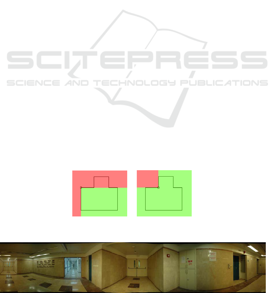
Finding the area in the floor-plan from which all
the corners can be seen is a form of a linear
programming problem for which there are numerous
efficient algorithms (De Berg, et al., 2008). Under
the assumption that all the corners are of ±90
degrees, the problem is largely simplified. For an
inward corner (concave), a quarter of the 2D space
can be discarded as an area from which the corner
cannot be seen (Figure 2, (b)). For an outward corner
(convex), three quarters of the 2D space can be
discarded as an area from which the corner cannot
be seen (Figure 2, (a)).
Repeating this process for each corner leaves
only the area from which all the corners are visible.
The center of this area is a good approximation for
the camera position in the floor-plan.
5 EXPERIMENTS
For the experimental validation of the proposed
approach we created panoramic images of several
indoor environments. The rooms we have used
include both large areas and long corridors. They
have only planar constant height walls, and
perpendicular corners. We placed a Nikon D70s
digital camera at the point from where all the corners
are visible and stabilized it on a tripod. The images
were taken using camera rotation only with an about
50% overlap. Then we created a 360
o
panorama
using a demo version of Autostitch(TM) software
(Brown, 2011). An example of such panorama of a
hall with the connected corridor is shown on Figure
3.
To enable user interaction with the panoramic
image we have built a MATLAB GUI that loads the
panorama and asks the user to mark all the corners.
Optionally, the "flat corners" can be easily marked
as well. Having the image and the corners, the floor
plan is reconstructed automatically together with the
estimated camera location (Figure 4).
For better visualization we add an arbitrary (but
reasonable) height to all the walls and color them
using texture mapping. The texture for each wall is
(a) (b)
Figure 2: Camera position estimation steps. A convex (a) and a concave (b) corners allow to discard parts of the plane (red).
Figure 3: A 360
o
panoramic image of a hall connected to a long corridor.
VISAPP 2012 - International Conference on Computer Vision Theory and Applications
348
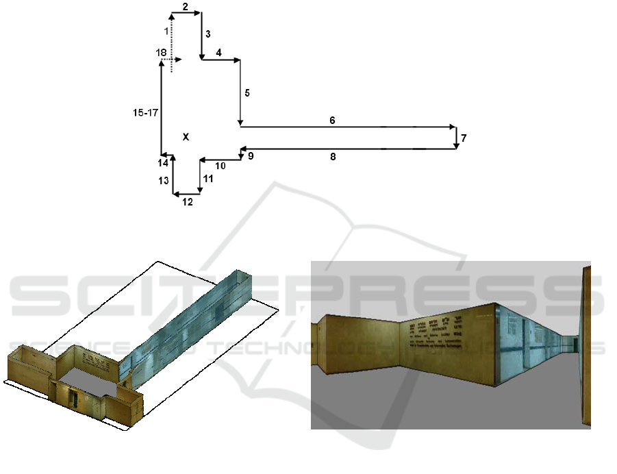
Figure 4: Sketch generation process with numbered steps. The dashed lines represent the extension of the first and last
vectors. The 'X' marks the estimated camera position.
(a)
(b)
Figure 5: The reconstructed room and corridor model from the 360
o
panorama in Figure 3. It is possible to receive an
overview of the whole scene from a distant point of view (a) or a partial view from within the room model (b).
created by unwarping the wall's image to the
corresponding rectangle. The rendered 3D model of
the room can be viewed from a bird's eye camera for
overview (Figure 5, (a)), or from any inside point for
detailed view (Figure 5, (b)).
As we can see for this space our algorithms
managed to reconstruct both the large hall in the
middle with all the corners and the long corridor.
Additional results are shown on Figure 6. On the
left (a) there is the reconstructed hallway from the
panorama and the corners of the Figure 1. It can be
seen that our approach handled the long and curved
wall as well as the short distant ones. On the right
(b) the T-junction of two corridors is reconstructed,
with both close and far away objects.
6 CONCLUSIONS
In this paper we have proposed a visualization
algorithm for 360
o
panoramic images of indoor
environments. Our algorithm reconstructs a 3D
model of the room and projects the panoramic image
onto the virtual walls. In addition, the camera
position is estimated for further applications. The
algorithm is user friendly and requires very small
user assistanse. Our experimental results show that it
is able to reconstruct a visualy accurate and realistic
model of the rooms in the panoramic images thus
helping the observer orient and understand the
spatial arrangement of the scene.
However, as mentioned in Section 2, the
panoramas are created by projecting the scene onto a
cylinder. The curvature imposed by this nonlinear
projection can interfere with some of the
calculations described in this work. This effect is
unnoticeable for walls that take only a small portion
of the panorama and the calculations are correct.
However, walls that capture a wide angle of view
appear curved in the image and the calculations
deviate from the truth. Our solution for these cases is
to ask the user for additional information in the form
of flat corners. Another approach may be finding the
correct inverse cylindrical transformation. Given the
SEMI-AUTOMATIC FLOOR-PLAN RECONSTRUCTION FROM A 360º PANORAMIC IMAGE
349
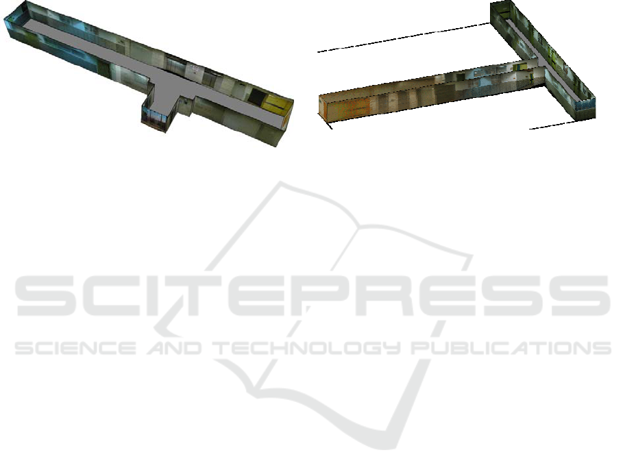
(a)
(b)
Figure 6: Additional 3D room models reconstructed from a single panorama.
inverse transformation the curved walls can be
transformed back into straight ones and the
calculations mentioned above are correct.
Another limitation is that the algorithm requires
all the walls and corners to be visible on one
panoramic image. This makes the algorithm not
suitable for the reconstruction from several
panoramas that were shot from different locations
and cover the whole scene when combined. For
example, a "U" shaped room cannot be captured by a
single panorama. A possible solution is to manually
combine the panoramic images into a single, longer,
image covering all the walls of the room. The
obtained panorama will contain all the needed data
for the reconstruction of the scene. However, the
camera position would be estimated separately for
each of the original panoramic images.
Inevitably, using pre-knowledge assumptions
about the room layout such as perpendicular walls
and constant ceiling height, limits the algorithm’s
universality. Nevertheless, the assumptions taken in
this paper hold for most standard room layouts and
allow a semi-automatic reconstruction with very
small user assistance.
In addition, since the algorithm generates the
floor-plan, it can be integrated with algorithms of the
second class mentioned in Section 1. Having a
relatively accurate initial geometric model of the
room and the camera position it is possible to
optimize the model ratios using the approach of
(Farin, et al., 2007) without any additional user
assistance. Another possibility is to use (Shum, et
al., 1998) for results optimization by employing
camera calibration and additional user assistance.
ACKNOWLEDGEMENTS
We would like to show our gratitude to CGM
laboratory’s staff, and thank Matthew Brown for
providing his Autostitch software.
REFERENCES
Brown, M., 2011. AutoStitch [Online] Available at: http://
www.autostitch.net/.
Brown, M. and Lowe, D.G., 2003. Recognizing
Panoramas. In: Proceedings of the 9th International
Conference on Computer Vision, pp. 1218–1225,
October 2003, Nice, France.
Brown, M. and Lowe, D. G., 2007. Automatic Panoramic
Image Stitching using Invariant Features.
International Journal of Computer Vision, 74(1), pp.
59-73.
De Berg, M. Cheong, O. and Van Kreveld, M., 2008.
Computational Geometry: Algorithms and
Applications, 3rd ed., Springer-Verlag.
Farin, D. and de With, P. H. N., 2005. Reconstructing
Virtual Rooms from Panoramic Images. In: 26th
Symposium on Information Theory in the Benelux, pp.
301–308, May 2005, Brussels, Belgium.
Farin, D. Effelsberg, W. and de With, P. H. N., 2007.
Floor-plan Reconstruction from Panoramic Images. In:
Proceedings of the 15th international conference on
Multimedia ACM, September 2007, Augsburg,
Germany.
Pollefeys, M. Koch, R. Vergauwen, M. Deknuydt A. A.
and Van Gool L. J., 2000. Three-dimensional Scene
Reconstruction from Images. SPIE Electronic
Imaging, Three-Dimensional Image Capture and
Applications III, 3958, pp. 215–226.
Shum, H. Y. Han, M. and Szeliski, R., 1998. Interactive
Construction of 3D Models from Panoramic Mosaics.
In: IEEE Conference on Computer Vision and Pattern
Recognition, pp. 427–433, June 1998, Santa Barbara,
USA.
Szeliski, R., 2010. Computer Vision: Algorithms and
Applications, Springer-Verlag.
Zelnik-Manor, L. Peters, G. and Perona, P., 2005.
Squaring the Circle in Panoramas. In: 10th IEEE
International Conference on Computer Vision, pp.
1292–1299, October 2005, Beijing, China.
VISAPP 2012 - International Conference on Computer Vision Theory and Applications
350
