3D MODELING OF STREET BUILDINGS FROM PANORAMIC
VIDEO SEQUENCES AND GOOGLE MAP IMAGE
Fay Huang
1
, Yi-Ju Wu
1
, Jing-Siang Hsu
1
and Augustine Tsai
2
1
CSIE, National Ilan University, 26047 Yi-Lan, Taiwan
2
Emerging Smart Technology Institute, Institute for Information Industry, 105 Taipei, Taiwan
Keywords:
Panoramic Images, Image-based Modeling.
Abstract:
A semi-automatic image-based framework for modeling of street buildings is proposed in this paper. Two
types of image sources are used, one is a sequence of ground-level spherical panoramic images captured by
panoramic video recorder, and the other is an aerial image of the desired area obtained from Google Map.
The advantages of our approach are first that the camera trajectory recovery result is more accurate and stable
due to that the spherical panoramic images are used if compared to multiview planar images. Second, since
each face texture of a building is extracted from a single panoramic image, there is no need to deal with color
blending problem while textures overlapped.
1 INTRODUCTION
Three-dimensional (3D) models of street scenes are
needed in many applications such as virtual fly/drive-
through, augmented reality, urban planning, and for
documentation purpose. Inventing a fully or semi-
automatic method for a fast building model recon-
struction has lately become a vivid research topic
in many fields such as computer graphics and vi-
sion. Due to the recent explosion of digital photogra-
phy, various image-based modeling approaches have
drawn a great deal of attention from many researches.
A detailed building reconstruction is not needed in
some applications such as virtual touring or path guid-
ing. One specific example would be the GPS-based
car navigation system, which mainly uses aerial sim-
plified street map incorporated with speech to guide
drivers to their destinations. Some advanced navi-
gation systems also support simple 3D models with-
out textures to illustrate the situations when multiple
roads vertically overlap. However, in many practi-
cal situations, drivers might still feel that it is quite
difficult to link the aerial 2D map or textureless road
models with the visual impression of the environment.
Thus, supplying realistic street views of the route can
be very useful, and this could be achieved by a set of
simple texture-mapped 3D building models.
Aerial images and ground-level images are two
major types of image sources used by many exist-
ing image-based urban 3D modeling approaches. City
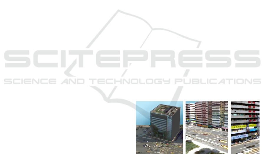
Figure 1: Examples of the reconstructed building models,
which are textured with building elevation images automat-
ically extracted from the panoramic images to provide the
realistic impression.
models can be constructed solely from aerial images
if the heights of the buildings can be obtained from
airborne laser scanners or calculated from stereo im-
age views (Gruen, 1997; Haala and Brenner, 1998;
Maas, 2001; Vestri and Devernay, 2001). How-
ever, the resultant city model usually lacks a realis-
tic impression at ground level since the aerial image
can only provide very limited texture information for
buildings’ side views. Hence, there have been a num-
ber of approaches to automated texture mapping of
3D models using the available ground-level images
(Fruh and Zakhor, 2004; Hu et al., 2006; Liu et al.,
2006; Stamos and Allen, 2002). The automated pose
recovery algorithm for multiview images was consid-
ered time-consuming and the textures generated from
different views usually causes a visible seam due to
109
Huang F., Wu Y., Hsu J. and Tsai A..
3D MODELING OF STREET BUILDINGS FROM PANORAMIC VIDEO SEQUENCES AND GOOGLE MAP IMAGE.
DOI: 10.5220/0003811301090114
In Proceedings of the International Conference on Computer Graphics Theory and Applications (GRAPP-2012), pages 109-114
ISBN: 978-989-8565-02-0
Copyright
c
2012 SCITEPRESS (Science and Technology Publications, Lda.)
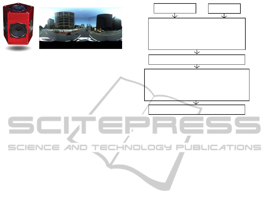
Figure 2: Left: Point Grey Ladybug3 panoramic camera.
Right: an example of the captured spherical panoramic im-
age.
lighting condition and image resolution variations.
Wang et al. (Wang et al., 2007) proposed to use cylin-
drical panoramic images for texture mapping propose.
In their method, a rough location of each panoramic
image was assumed provided and the registration be-
tween the panoramic image and aerial image was
done through a voting process. Since only sparse
panoramic images were used, some building might be
lack of texture or there exist some visible seams while
textures overlapped.
Panoramic images have become widely accessible
due to the rapid development on hardware and cam-
era technologies, and they have many advantages in
supporting the 3D reconstruction tasks due to their
wide field-of-view. We aim to develop a framework
which takes a set of dense spherical panoramic im-
ages and an orthogonal aerial image of that area, and
is able to output the texture maps and height infor-
mation of the selected buildings through a fully au-
tomatic process. The reconstructed building models
are textured with building elevation images extracted
from the panoramic images to provide the realistic im-
pression as shown in Fig. 1. The proposed approach
would be useful for applications that require large-
scaled and simple yet realistic 3D street/city models.
2 RECONSTRUCTION
FRAMEWORK
The framework takes two types of image sources as
input. One is a dense set of ground-leveled panoramic
images and the other is an nearly-orthogonal aerial
image of that area. The 360×360-degree panoramic
images were captured by Point Grey Ladybug3
mounted on the top of a car, which captured five “reg-
ular” planner images looking horizontally outwards
and one looking upward, each with frame rate of 15
images per second. Six images are then stitched to-
gether using the multi-perspective plane sweep ap-
proach of (Kang et al., 2004). This allows to pro-
duce a set of spherical panoramic images of resolu-
Feature Detection and Matching
Aerial and Panoramic Image Registration
External Camera Parameter Determination
Camera Trajectory Recovery
Building Rooftop Edge Detection and Matching
Building Height Estimation and Texture Extraction
Building Texture Rectification
Panoramic Images
Aerial Image
3D Modeling and Texture Mapping
Figure 3: Framework of the proposed approach.
tion 2048×1024. The camera and an example of the
captured panoramic image are shown in Fig. 2. The
aerial image of the desired area can be obtained from
Google Map by stitching together different image por-
tions, each shows the largest zoom in view, of that
area.
Some reasonable assumptions about the input data
of our approach is described as follows: The projec-
tion model of each source panoramic image can be
modeled by the spherical projection with respect to
a point (i.e., a projection center) representing the lo-
cation of the camera in 3D space where the image
was captured. An imaging coordinate system is de-
fined for each image originated at its corresponding
projection center. Moreover, the panoramic images
were acquired along a smooth and continuous path.
The GPS position information associated with some
panoramic image acquisition locations is given as the
car was equipped with the GPS device. The informa-
tion is used for initialization and bundle adjustment
purposes. Furthermore, the buildings’ footprints on
the orthogonal aerial image are given (i.e., by pre-
processing the aerial map same as method proposed
in (Wang et al., 2007)) or manually specified. The
outlines of building footprints are used to construct
the 3D models of the buildings and also help identify-
ing the buildings’ front view regions in the panoramic
images.
The framework of our approach is depicted in
Fig. 3. First, feature detection algorithm is applied to
each of the source panoramic images, and then feature
point matching search is performed between each pair
of successive images. The matching results enable us
to recover the essential matrix describing the spatial
GRAPP 2012 - International Conference on Computer Graphics Theory and Applications
110

relationship between two imaging coordinate sys-
tems. The relative orientation, represented by a rota-
tion matrix, and position, represented by a unit vector,
of two successive panoramic images can be derived
from the essential matrix. Camera trajectory can be
recovered through point cloud reconstruction of the
scene and bundle adjustment based on the available
GPS information. The camera path can be refined
through the process of registering it to the aerial im-
age. After each panoramic image’s position with re-
spect to the aerial image’s coordinate system is estab-
lished, the building rooftop edges on the panoramic
images can be identified through a matching process
supported by the information of building footprint
outlines on the aerial image. The height of build-
ing can be calculated based on the detected building
rooftop edge and the location of the panoramic image.
Finally, the building texture can be extracted form the
panoramic image, and it must go through warping and
rectification processes before can be used for texture
mapping. The reminding sections report techniques
used in the framework followed by some 3D model-
ing results and conclusions.
3 CAMERA TRAJECTORY
RECOVERY
The first half of the framework deals with the camera
trajectory recovery task, which can be considered as
a preparation step so that the registration of two types
of input images can take place. Currently, registering
the recovered camera trajectory to the aerial image is
done manually by specifying two end point locations
of the path on the map. Consequently, an image’s co-
ordinates representing a position on the aerial image
associated with each source panoramic image could
be derived.
In order to recover the relative image capturing
positions and orientations of the source panoramas,
we first estimated the spatial relationship between
each adjacent pair of panoramic images, and then in-
tegrated those pairwise results. The spatial relation-
ship in terms of a rotation matrix and a translation
vector, referred to as the external camera parameters,
can be derived from the essential matrix describing
the epipolar constraint between the image correspon-
dences in two panoramas.
The image point correspondences can be estab-
lished by Scale-invariant Feature Transform (SIFT)
detection plus SIFT-based matching. A single thresh-
old D
SIFT
was used to determine if a match was ac-
ceptable in the SIFT-based matching algorithm. The
smaller the value, the more image correspondences
Figure 4: An intermediate result of the reconstructed scene
point cloud for determining the external camera parameters.
Blue dots represent the calculated scene points and red cir-
cles indicate the camera positions.
were identified, and the higher possibility that the re-
sult would include false matches. The eight-point al-
gorithm was employed to estimate the essential ma-
trix. A two-pass approach was proposed to obtain the
final essential matrix. First, an initial essential ma-
trix was derived according to a smaller set of image
corresponding points, which was the matching result
associated to a relatively large threshold value D
SIFT
.
Those sparse corresponding points were believed to
be more accurate but less descriptive. Next, a smaller
threshold value was assigned to obtain a larger set of
point matches. The initial essential matrix was then
used to serve as a constraint to filter out the incorrect
matches. In other words, the matching outliers were
filtered by epipolar constraint. The remaining point
matches were then used to compute the final essential
matrix.
The derived essential matrix was used to solve for
the external camera parameters R and T, which stand
for the rotation matrix and the translation vector, re-
spectively. Pairwise external camera parameters were
first determined and then integrated one by one to
obtain the global camera motion and thus the cam-
era’s moving trajectory. During the integration pro-
cess, the scene points based on the already processed
panoramic image were reconstructed with respect to
the 3D world coordinate system, which are used as
the references to estimate the next camera location.
An example illustrating an intermediate result of the
reconstructed scene point cloud is given in Fig. 4. The
major drawback of such method is that the camera pa-
rameter estimation error would propagate through the
integration process. One way to correct such drift is
by a path closing strategy, which however does not al-
ways work well. Moreover, identifying two or more
panoramic images captured at the same street inter-
section but at different locations and times is a very
3D MODELING OF STREET BUILDINGS FROM PANORAMIC VIDEO SEQUENCES AND GOOGLE MAP IMAGE
111

difficult problem. In order to deliver an efficient and
relatively more accurate solution to this problem, we
have chosen to incorporate GPS information. Since
the accuracy of GPS system varies from 1 to 5 meters,
it is sensible to correct the trajectory drift every 50
meters based on the GPS reading. The final camera’s
moving trajectory was determined by a series of bun-
dle adjustments on the recovered camera locations.
4 GENERATION OF BUILDING
TEXTURE MAPS
The second half of the framework deals with the
generation of building texture maps from the source
panoramic images. A building can be identified
through the processes of image edge detection and
line matching with the supportive information of the
provided building footprint boundaries on the aerial
image. The usage of texture maps not only can en-
hance the visualization of the 3D models but also of-
fer the height information of the buildings, which is
needed in the building modeling process.
For each building shown in the aerial image, we
are mainly interested to extract the front elevation
portion of the building from the panoramic image.
Due to that a dense set of panoramic images were ac-
quired, the same building will appear on numbers of
successive panoramic images. Thus, it is essential to
look for a source panoramic image which contains a
largest projection region of the desired building. This
panoramic image, denoted by P
i
, can be obtained by
the following:
i = argminDist
(x
j
,y
j
),(
x
s
+ x
e
2
,
y
s
+ y
e
2
)
∀ j ∈ {1,2, ...,N},
where Dist function returns the distance between two
coordinate locations on the plane (i.e., the aerial im-
age space), (x
j
,y
j
) represents the location of the j-th
panoramic images, (x
s
,y
s
) and (x
e
,y
e
) represent the
starting and ending points of the given building foot-
print edge, respectively, and N denotes the total num-
ber of candidate panoramic images.
The building footprint line segment on the aerial
image was projected to the panoramic image. Let
u
s
and u
e
denote the projections of the starting and
ending points of the footprint edge, respectively. In
order to identify the image portion that contains the
front elevation view of the desired building, we first
reduced our searching space by defining a horizontal
range [u
l
,u
r
], where u
l
< u
r
and u
l
,u
r
∈ {1,2,.. .,W}.
We have
u
l
= min(u
s
,u
e
) − |u
s
− u
e
|/4
u
r
= max(u
s
,u
e
) + |u
s
− u
e
|/4,
where W is the width of the panoramic image (in
pixels). We use H to denote the image height. We
could further reduce the searching space by defining
a vertical range [v
t
,v
b
], where u
t
< u
b
and u
t
,u
b
∈
{1,2, ...,H}. These two boundary values can be ob-
tained by the elevation of the camera location, de-
noted as h, the shortest distance between the camera
and the building, denoted as d, and the maximum pos-
sible height of the building, denoted as b. We have
v
b
= H ×
arctan(h/d)
π
+
1
2
v
t
= H ×
1 −
arctan((b − h)/d)
π
.
The image region bounded by top-left corner
(u
l
,v
t
) and bottom-right corner (u
r
,v
b
) is denoted by
I
R
. We applied Canny edge detection to region I
R
and back-project the resultant binary image to a pla-
nar surface, denoted as I
P
. Then, Hough transform
was employed to detect straight lines. We have posed
constraints that the length of the straight line must be
greater than half of the width of region I
R
and the
angle between the straight line and a horizontal axis
should be less than 45
◦
. The set of detected straight
lines potentially contains the desired building rooftop
edge. Let S denote the number of resultant straight
lines.
The building footprint boundary on the aerial im-
age, the one facing the camera, was projected to
the panoramic image by various b values within rea-
sonable building height range B, and as well as at
the same time back-projected onto I
P
. A similarity
test was then performed to calculate the number of
overlapped pixels between each of the back-projected
building footprint boundaries and the set of detected
straight lines. The desired building rooftop edge, de-
noted as l
m
, can be estimated by the followings:
(m,r)=arg max(Simility(l
n
, f
b
)+Length(l
n
)−Row(b))
∀n ∈ {1,2,. . .,S} and ∀b ∈ B,
where l
n
indicates the detected straight line indexed
as n, f
b
indicates the back-projected building footprint
boundary with height value equals to b, and function
Row returns the average image row of f
b
in I
P
. The
obtained value of r indicates the height of the build-
ing.
The building elevation view image was generated
by first back-project the color panoramic image re-
gion I
R
to a planar surface, denoted as I
Q
. The reso-
lution of color image I
Q
is identical to the resolution
GRAPP 2012 - International Conference on Computer Graphics Theory and Applications
112

Figure 5: The aerial view of the interested building to be
reconstructed. The red line segment indicates the building
footprint boundary and the red dot on the street indicates the
camera location where Fig. 2(right) was captured.
of binary image I
P
. In general, the resultant texture
image I
Q
is not in rectangular shape. Rectangular im-
age textures of building elevation views are preferred
for texture mapping task. Therefore, image I
Q
needed
to be rectified by the perspective transformation pro-
vided in OpenCV before it was used for texture map-
ping.
5 EXPERIMENTAL RESULTS
The program was mainly written in MATLAB and
partially in C++. The experiments were performed
on Windows XP (Service Pack 3) operating system
running on a Intel(R) Core(TM) i7 CPU 920 2.67
GHz with 3G of RAM. A Point Grey Ladybug3 digi-
tal video camera was mounted on top of a car and used
to capture the input panoramic images. The car was
moving at an average speed of 45 kilometers per hour
on the street and the camera captured 15 panoramic
images per second. This way, adjacent panoramic
images were captured at locations approximately one
meter apart. The car was also equipped with a GPS
system.
The input panoramic image resolution was equal
to 2048(width) × 1024 (height) pixels. An example of
the captured spherical image is shown in Fig. 2(right),
which has been transformed to a planar rectangular
image. The aerial image of that area was obtained
from Google Map as shown in Fig. 5, where the red
line segment indicates the provided building footprint
boundary and the red dot on the street indicants the
corresponding camera location where Fig. 2(right)
was captured.
We recorded thousands of panoramic images this
way on different streets, however, for image exper-
Figure 6: Building texture generation example. (Top) the
captured panoramic image. The red rectangle encloses the
region that contains the desired building texture. (Left) the
Canny edge detection result of the building region after per-
forming the back-projected. The image has been faded to
emphasize the detected straight lines. (Middle) the gener-
ated building texture, and (right) the result after performing
the perspective transformation.
iments there is no sufficiently accurate ground truth
data available for evaluation. As described in the
previous sections, we aim to reconstruct a rough 3D
street model for which accuracy was not our major
concern. Some reconstruction examples based on our
approach are shown in Fig. 1.
A building texture generation example is given in
Fig. 6. The original panoramic image is shown on
the top. The red rectangle indicates the region I
R
that
contains the desired building texture, which is back-
projected to a planar surface I
P
to perform straight
line detection. Figure 6(left) illustrates the Canny
edge detection result of I
P
in binary image format.
Hough line detection algorithm has been performed
to obtain a set of nearly horizontally-oriented straight
lines. The binary image has been faded to emphasize
the detected straight lines (blue thin lines). Red thick
lines indicate the potential building roof. Finally, the
top-most thick black line has been identified to be the
building rooftop edge. Part of the top region of the
back-projected color panoramic image was cropped
according to this identified building rooftop edge, and
the result is shown in Fig. 6(middle). The perspective
transformation has been performed to obtain a rectan-
gular building texture illustrated on the right of Fig. 6.
Another building texture generation example is shown
in Fig. 7 and the corresponding reconstruction result
is shown in Fig. 1(left).
3D MODELING OF STREET BUILDINGS FROM PANORAMIC VIDEO SEQUENCES AND GOOGLE MAP IMAGE
113
(a) (b)
Figure 7: Another texture rectification example. (a) is the
generated building texture, and (b) is the result after per-
forming the perspective transformation.
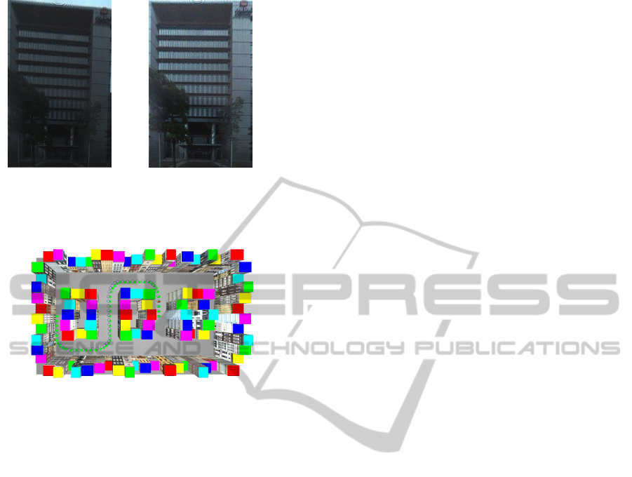
Figure 8: Camera trajectory recovery result of synthetic ex-
periment.
To evaluate the performance of the proposed cam-
era trajectory recovery approach, we have also con-
ducted some synthetic experiments. A 12 × 20 units
(note: the unit is as used in the software) virtual street
model was built by Maya and all the buildings were
texture mapped with real images. A virtual camera
was implemented to capture the panoramic images in
the virtual world. For the experiment illustrated in
Fig. 8, 50 panoramic images were generated at the lo-
cations indicated by green dots. The estimated cam-
era path is represented by a set of blue circles. The
average drifts of the resulting camera path to the ac-
tual path is equal to 0.324 units.
6 CONCLUSIONS
An street 3D modeling framework was proposed,
which takes two types of images as input sources,
namely a set of spherical panoramic images captured
along a continuous path and an orthogonal aerial im-
age of that area. The relative orientations and posi-
tions of all the panoramic images can be recovered
through a fully automatic process with the help of
sparse GPS data. The footprints of major buildings
to be reconstructed in the aerial image are assumed
given. The developed program is able to automati-
cally estimate the height information and generate a
rectangular front view texture image of each building
for large-scaled 3D city modeling.
ACKNOWLEDGEMENTS
This project is financially sponsored by National Sci-
ence Council (grand no. NSC 100-2221-E-197 -
028). Some preliminary experiments were financially
sponsored by MOEA (ministry of economics affairs)
project no. 98-ec-17-A-02-01-00809. The authors
would like to express special thanks to Akihiko Torii
for useful discussions and Jui-Yang Tsai for image ac-
quisitions.
REFERENCES
Fruh, C. and Zakhor, A. (2004). An automated method for
largescale, ground-based city model acquisition. In-
ternational Journal of Computer Vision, 6:5–24.
Gruen, A. (1997). Automation in building reconstruction.
In Proc. Photogrammetric Week97, pages 175–186,
Wichmann Verlag, Heidelberg.
Haala, N. and Brenner, C. (1998). Fast production of virtual
reality city models. In Proc. IAPRS, pages 0–0, 0.
Hu, J., You, S., and Neumann, U. (2006). Automatic pose
recovery for high-quality textures generation. In Proc.
ICPR, pages 561–565, Hong Kong, China.
Kang, S.-B., Szeliski, R., and Uyttendaele, M. (2004).
Seamless stitching using multi-perspective plane
sweep. In MSR-TR-2001-48.
Liu, L., Stamos, I., Yu, G., Wolberg, G., and Zokai, S.
(2006). Multiview geometry for texture mapping 2d
images onto 3d range data. In Proc. CVPR, pages
2293–2300, Washington, DC, USA.
Maas, H.-G. (2001). The suitability of airborne laser scan-
ner data for automatic 3d object reconstruction. In
Third International Workshop on Automatic Extrac-
tion of Man-Made Objects from Aerial and Space Im-
ages, pages 10–15, Monte Verita, Ascona, Switzer-
land.
Stamos, I. and Allen, P. K. (2002). Geometry and texture
recovery of scenes of large scale. Comput. Vis. Image
Underst., 88:94–118.
Vestri, C. and Devernay, F. (2001). Using robust methods
for automatic extraction of buildings. In Proc. CVPR,
pages 133–138, Kauai, HI, USA.
Wang, L., You, S., and Neumann, U. (2007). Semiautomatic
registration between ground-level panoramas and an
orthorectified aerial image for building modeling. In
Proc. VRML07 ICCV07 workshop, pages 8–15, Rio
de Janeiro, Brazil.
GRAPP 2012 - International Conference on Computer Graphics Theory and Applications
114
