
DENSE PIXEL MATCHING BETWEEN UNRECTIFIED AND
DISTORTED IMAGES USING DYNAMIC PROGRAMMING
Jerome Thevenon, Jesus Martinez-del-Rincon, Romain Dieny and Jean-Christophe Nebel
Digital Imaging Research Centre, Kingston University, Penhryn Road, Kingston-Upon-Thames, KT1 2EE, Surrey, U.K.
Keywords: Stereo Correspondence, Dynamic Programming, Unrectified Images, Distorted Images.
Abstract: In this paper, a novel framework for dense pixel matching based on dynamic programming is introduced.
Unlike most techniques proposed in the literature, our approach assumes neither known camera geometry
nor the availability of rectified images. Under such conditions, the matching task cannot be reduced to
finding correspondences between a pair of scanlines. We propose to extend existing dynamic programming
methodologies to a larger dimensional space by using a 3D scoring matrix so that correspondences between
a line and a whole image can be calculated. After assessing our framework on a standard evaluation dataset
of rectified stereo images, experiments are conducted on unrectified and non-linearly distorted images.
Results validate our new approach and reveal the versatility of our algorithm.
1 INTRODUCTION
Dense pixel matching is a low-level process which is
involved in many computer vision applications
including navigation, security, entertainment and
video surveillance. Not only is it often an essential
step in 3D reconstruction from a pair of stereo
images, but it is also used in object detection and
video tracking, especially when the camera is not
fixed (Note, et al., 2006); (Yaguchi,, et al., 2009) as
it is the case with camera phones (Yin, et al., 2007).
Recent reviews describe and analyse the many
algorithms which have been proposed to address this
matching process (Scharstein and Szeliski, 2002),
(Lazaros, et al., 2008). Most approaches performing
dense pixel matching assume images have been
rectified so that their task can be reduced to finding
correspondences between a pair of scanlines. Among
these techniques, those based on dynamic
programming (DP) are of particular interest since
they combine good accuracy with low computational
complexity as demonstrated by a recent real-time
FPGA hardware implementation (MacLean, et al.,
2010). Their main drawback is that they require the
knowledge to project images onto a common
coordinate system. Although, in many applications
those transformations can be estimated by either
camera calibration or image rectification, calibration
is sometimes either impossible or impractical,
whereas the computational cost of accurate
rectification models prohibits their usage in real-
time application. Moreover, none of these methods
is suitable when a camera lens displays unexpected
distortions, such as those generated by raindrops,
weatherproof covers or dust.
In this paper, we propose a novel DP-based
dense pixel matching algorithm which can handle
unrectified and non-linearly distorted images. After
a state-of-the-art review, we detail our novel
matching algorithm. Finally, it is validated with
experiments conducted on unrectified images and
images displaying significant deformations.
1.1 Related Work
Generally, pixel matching approaches (Barnard, et
al., 1982); (Dhond, et al., 1989), (Brown, et al.,
1992); (Jones, et al., 1997); (Scharstein and Szeliski,
2002) assume that images have been rectified so that
the task is simplified to establishing
correspondences between corresponding rows of the
rectified images. The standard process for
rectification is homography based, also called planar
rectification, where image planes are transformed so
that the corresponding space planes coincide
(Ayache and Hansen, 1998); (Hartley, 1999). A
major limitation of this class of approaches is that, if
epipoles are located in the images, planar
rectification produces infinitely large images. This
problem has now been solved under specific
216
Thevenon J., Martinez-del-Rincon J., Dieny R. and Nebel J..
DENSE PIXEL MATCHING BETWEEN UNRECTIFIED AND DISTORTED IMAGES USING DYNAMIC PROGRAMMING.
DOI: 10.5220/0003812602160224
In Proceedings of the International Conference on Computer Vision Theory and Applications (VISAPP-2012), pages 216-224
ISBN: 978-989-8565-04-4
Copyright
c
2012 SCITEPRESS (Science and Technology Publications, Lda.)

conditions by using either cylindrical (Roy, et al.,
1997) or spherical rectifications (Pollefeys, et al.,
1999); (Wan and Zhou, 2008). In addition to adding
significant computational complexity, these methods
still overlook issues such as sub pixel coordinates,
infinite epipoles (Lim, et al., 2004) and the non
preservation of conjugate epipolar polarities (Oram,
2001). An alternative to these approaches is to fully
calibrate cameras to estimate the appropriate
transformation between images. However, since this
process is usually manual or relies on very specific
environments, its usage has very strong limitations.
In any case, all these methods depend on finding a
set of accurate matching points, resampling images
and appropriate lens distortion models, of all which
affect the matching performance. Moreover, there
are scenarios where these methods are totally
inadequate. For example, visual tracking is seriously
degraded by weather conditions when the presence
of water drops produces undesirable temporal and
localised distortions (Barnum, et al., 2007); (Garg
and Nayar, 2004); similarly, vision systems on space
exploration rovers are affected by dust accumulation
(Willson, et al., 2005).
Although performing dense pixel matching
without prior image transformation is an attractive
proposition, very few algorithms have been
suggested. This problem was addressed using either
multi-resolution image correlation (Duchaineau, et
al., 2007); (Zhengping, 1988) or a genetic algorithm
(Tippetts, et al., 2010). It was also suggested that a
self-organizing neural network could potentially be
used under these conditions (Vanetti, et al., 2009).
Unfortunately, all these methods display high
computational complexity and recursivity, which
makes them unsuitable for real-time and hardware
implementations.
This review highlights the limitations of
rectification and calibration procedures and shows
that, currently, bypassing this step leads to solutions
with high computation costs. In order to address this,
a novel algorithm could be designed by extending
one of the approaches developed to tackle in real-
time the simpler task of scanline matching
(Forstmann, et al., 2004); (Gong, et al., 2006), (Lu,
et al., 2009); (Salmen, et al., 2009); (Wang, et al.,
2006); (Yang, et al., 2006). Among them, techniques
based on DP seem particularly suitable: although
they are not the most accurate, performance analysis
has shown they provide an excellent compromise
between accuracy and speed (Cox, et al., 1996);
(MacLean, et al., 2010); (Scharstein and Szeliski,
2002); (Brown, et al., 2003); (Tappen and Freeman,
2003). Their low intrinsic computational complexity
even led to a recent FPGA hardware implementation
(MacLean, et al., 2010).
In this paper, we propose a novel dense pixel
matching algorithm based on the DP paradigm
which can operate with unrectified images without
camera calibration.
2 ALGORITHM
We propose a novel dynamic programming
algorithm which is able to establish dense pixel
correspondences between two unrectified and/or
distorted images. Since our method is based on a DP
approach, it relies on two main steps: the storage of
local calculations and their reuse to produce a global
solution. In this section, we first describe how a 3D
scoring matrix is computed. Then, we propose a
refinement of these calculations, i.e. introduction of
the extended gap concept. Finally, we detail the
backtracking phase which allows generating optimal
global correspondences.
It is important to note that, although the usage of
3D matrices within DP based pixel matching
algorithms was proposed by Sun (Sun, 2002); (Sun-
2, 2002), this was only a means of efficiently
calculate the correlations over a sliding window.
This did not address the requirement of image
rectification and was only suitable for scanline
matching.
2.1 3D Scoring Matrix
Similarly to many dynamic programming-based
algorithms designed for scanline matching (Geiger,
et al., 1992); (Belhumeur, 1996); (Cox, et al., 1996);
(Torr and Criminisi, 2004), the first stage of our
algorithm fills in a scoring matrix according to a
given scoring scheme. However, our approach does
not restrict itself to finding pixel correspondences
between scanlines, but between a scanline and an
entire image. The strength of this scheme is that
images do not need to be rectified and matching can
be achieved even when one of the images displays
important distortions. Consequently, a scanline on
the first image does not need to match a straight line,
but may correspond to a curve in the second image
(see Figure 1). Since this algorithm is an extension
of an algorithm designed for matching stereo pairs
of images (Authors, 1111), we use the same
convention: the first and second images are referred
as the left and right images.
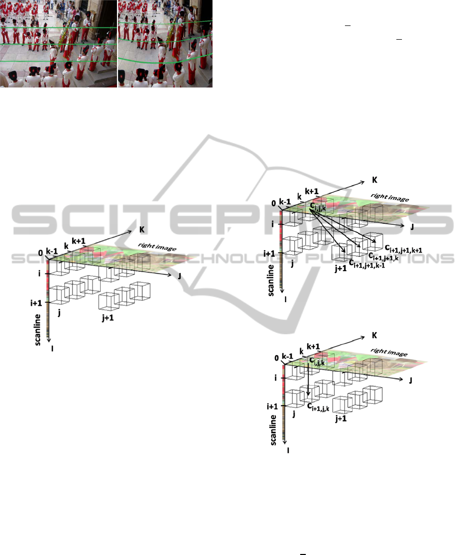
First, a 3D scoring matrix is generated for each
scanline s of the left image. Assuming the left image
DENSE PIXEL MATCHING BETWEEN UNRECTIFIED AND DISTORTED IMAGES USING DYNAMIC
PROGRAMMING
217
a) b)
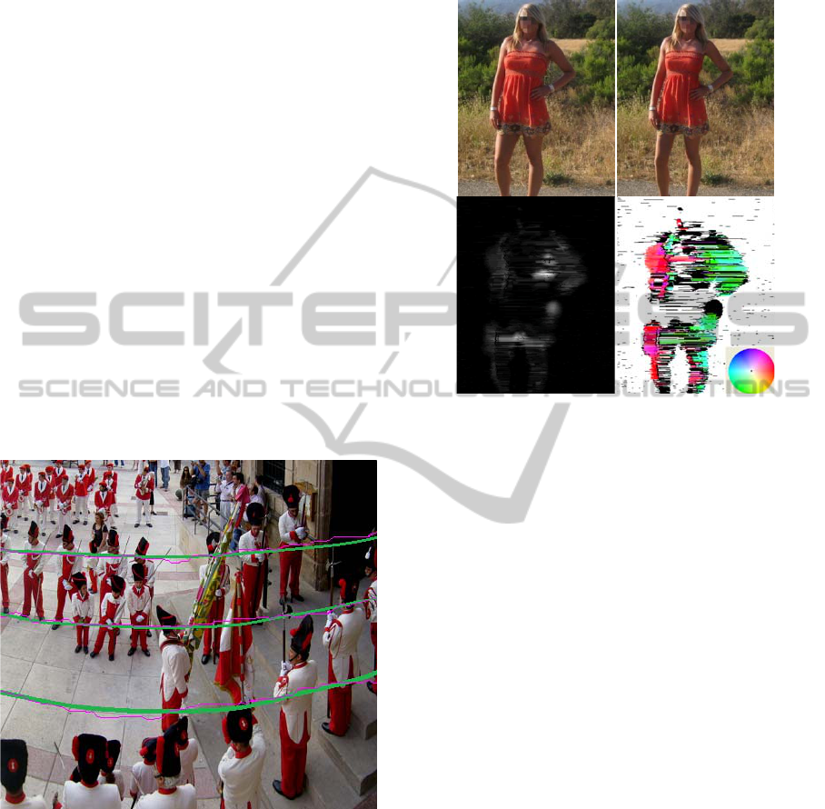
Figure 1: Views of the same scene captured using different
camera lenses. Green curves: groundtruth correspondence
between 3 scanlines of image a) and pixels of image b).
scanlines have a length L and the dimensions of the
right image are WxH (width x height), the size of the
scoring matrix, sc, is LxWxH. A matrix cell c
i,j,k is
defined by three coordinates, where i represents the
elements of the scanline and j and k the column and
line of the right image (see Figure 2).
Figure 2: 3D scoring matrix.
Matrix cells store the maximum value which can
be achieved by extending a previous alignment.
When a DP approach is used to find
correspondences between two scanlines, an
alignment can only be extended in three manners:
pixels of the left and right images may have similar
values, i.e. there is a match, or one of the pixels may
be occluded in either the first or the second
sequence, i.e. a gap has to be introduced. Here, an
alignment finishing in the cell, c
i,j,k, can be extended
in seven ways.
Since a match means that a pixel of the scanline
corresponds to a pixel in the image, the matching
cell must be contiguous to the previous cell, c
i,j,k.
Moreover, dynamic programming approach requests
moving forward in order to come to an end.
Consequently, a match can occur in either cell
c
i+1,j+1,k, ci+1,j+1,k+1 or ci+1,j+1,k-1, which corresponds to
a correspondence between the next pixel in the
scanline (i+1), and respectively, the next pixel in the
next column (j+1) in the same line (k), match m
1, the
line below (k+1), match m2, or the line above (k-1),
match m
3 (see Figure 3).
Since a change of line and column means
moving by a distance of
√
2
pixels in the image, this
implicitly adds a virtual gap of
√
2
−1pixels.
Therefore, this type of match should be less
rewarded than a match along the i+1,j+1,k direction.
If matches between pixels cannot be found, a gap
has to be introduced in either the image or the
scanline. A gap in the image indicates that a scanline
pixel does not have any correspondence in the
image: this pixel is occluded in the right image.
Consequently, the alignment is extended by moving
to the next element in the scanline, i.e. c
i+1,j,k (gap
g4) (see Figure 4).
Figure 3: Matching.
Figure 4: Gap in the image.
Alternatively, image pixels may be occluded in
the left image. This implies not moving in the I
direction, i.e. the displacement in the matrix is
towards either c
i,j+1,k (gap g1), ci,j+1,k+1 (gap g2) or
c
i,j+1,k-1 (gap g3) (see Figure 5). Similarly to the case
of matching, a change of line implies adding an
extra gap of
√
2
−1pixels, which also needs to be
penalised.
As shown, each cell of the 3D scoring matrix can
be accessed from 7 directions. During the filling
process, for each of these directions the cell value is
calculated according to the cost of the move, i.e.
match or gap costs: the highest value and the
VISAPP 2012 - International Conference on Computer Vision Theory and Applications
218

direction(s) it is coming from are stored in the cell.
This information is used in the backtracking process.
Figure 5: Gap in the scanline.
In order to define the costs of these possible
moves, we introduce 3 parameters: m is the reward
for a perfect match, g is the penalty for a single gap,
and Δ is the penalty for an imperfect match, which is
set at the absolute value of the intensity difference
between the scanline pixel, s(i), and the image pixel,
Im(j,k).
Δ=
|
() − (,)
|
(1)
Using these parameters, the cost of adding an extra
gap of
√
2
−1pixels, p, can be expressed by:
=
√
2
−1(−) (2)
Before starting the filling process, the matrix
needs to be initialised. First, the initial alignment
score is set to zero. This involves extending the
initial matrix of dimensions LxWxH with the planes
(0,J,K) and (I,0,K). Since the alignment can start
from any line of the image, cells with coordinates
i=0 and j=0 are filled with zeros. Then other cells
from the planes (0,J,K) and (I,0,K) are initialised
according to cumulated gap penalties.
Finally, the scoring matrix, sc, is filled in
according to the following pseudo-code:
for i=1 to L
for j=1 to W
for k=1 to H
Δ ← |s(i)-Im(j,k)|
m1 ← sc(i-1,j-1,k)+m-
Δ
m2 ← sc(i-1,j-1,k+1)+m-Δ-p
m3 ← sc(i-1,j-1,k-1)+m-Δ-p
g1 ← sc(i,j-1,k)+m-g
g2 ← sc(i,j-1,k+1)+m-g-p
g3 ← sc(i,j-1,k-1)+m-g-p
g4 ← sc(i-1,j,k)+m-g
sc(i,j,k) ← max(m1,m2,m3,g1,g2,g3,
g4)
end for
end for
end for
As a consequence, the time complexity of the
proposed algorithm is
(
)
per scanline.
2.2 Extended Gap
In the initial scoring scheme, each individual gap has
a fixed penalty. However, due to the nature of stereo
images and successive video frames where different
perspectives create partial object occlusions,
occluded pixels tend to cluster instead of being
equally distributed across an image. We propose to
exploit this observation by introducing a lower
penalty for new gaps which extend existing gaps. An
affine gap penalty is used where the initial gap
opening penalty is set at g and each extension of a
gap increases the total penalty by a lower value, e,
(e<g). Consequently, a gap of length l will only
encounter a penalty of +
(
−1
)
in this new
scheme.
2.3 Backtracking
Once the 3D scoring matrix has been filled, global
alignment(s) between the scanline and the image are
recovered by backtracking. This is achieved, first, by
retrieving in the matrix cell with the highest score
obtained for a global alignment. Then, from that cell,
using the stored direction information, one or more
paths are reconstructed to the origin of the matrix
and converted into alignments.
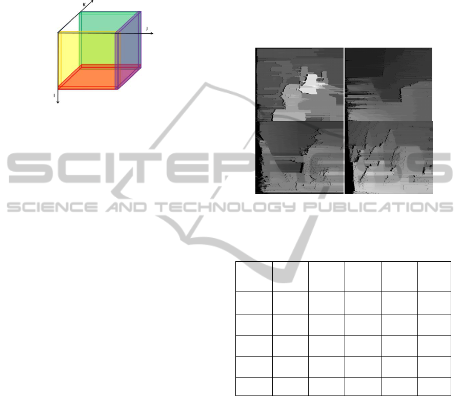
Global alignment scores are found in four planes
of the matrix (see Figure 6). If the last pixel of the
scanline corresponds to a pixel of the image, global
scores are recorded in the plane i = L (orange plane,
Figure 4). Alternatively, the end of the scanline may
not have any correspondence in the image because it
belongs to a non overlapping region. As a
consequence, the last scanline pixel with an image
pixel match would be located on one of the borders
of the image. This score could be read in either the
plane k = 1 (yellow plane, top of the image), the
plane k = H (green plane, bottom of the image) or
the plane j = W (purple plane, right of the image).
From the cell(s) with the highest score within
these four planes, global alignment are discovered
by backtracking inside the matrix using the stored
information regarding the direction(s) the score of
the cell of interest is coming from. Since a cell score
comes from the highest value among seven
directions, two or more directions could lead to
equal maximum scores. Consequently, during
backtracking several optimal alignments could be
produced. Although strategies, such as choosing the
solution which is the most consistent with this of the
DENSE PIXEL MATCHING BETWEEN UNRECTIFIED AND DISTORTED IMAGES USING DYNAMIC
PROGRAMMING
219
previous scanline, can be used to adopt the most
likely path, in this work, a unique alignment is
generated by selecting at random one of the global
solutions.
Figure 6: Location of global alignment scores.
3 EXPERIMENTAL RESULTS
In order to validate the proposed algorithm a set of
experiments were conducted. First, the algorithm is
evaluated using a standard stereo matching
evaluation framework using rectified images. Then,
the potential of our approach is demonstrated by
processing unrectified and non-linearly distorted
images.
Although parameters are optimised for each
stereo pair using the rectified image scenario, typical
values are m=256, g= 181 and e=156. Since the
processing of disparity maps by a median filter
increases accuracy by enforcing some inter-scanline
continuity (Veksler, 2005) (Deng and Lin, 2006), in
some experiments, we apply this filter in a post-
processing step.
3.1 Rectified Images
Our algorithm was first evaluated using the
Middlebury Stereo Evaluation framework
(Scharstein and Szeliski, 2003) which is widely used
as a benchmark tool by the computer vision
community when assessing performance of
matching algorithms between rectified images.
Initially, we validate our DP implementation by
disabling the ability of changing lines in the scoring
matrix. Therefore, it takes advantage of the fact that
images are known to be rectified. Table 1 shows
that, once a median filter is applied onto the raw
disparity maps, this basic version of the proposed
algorithm (Rectified), that was introduced in a
previous paper (Dieny, 2011), performs similarly to
Bobbick et al. (Bobick and Intille, 1999), which is
the reference among standard DP approaches.
Performances of the proposed algorithm
(Unrectified) are also provided in Table 1. Although
the ability to change lines degrades significantly
stereo matching accuracy, the quality of produced
disparity maps remains reasonable (Figure 7). In the
next section, we show that this performance
reduction in the case of rectified images is rewarded
by the ability to process more complex sets of image
pairs.
Figure 7: Raw disparity maps obtained for Middlebury
dataset (Unrectified).
Table 1: Performance comparison using the Middlebury
Stereo Evaluation framework.
%
Tsukuba
(non occ)
Venus
(non occ)
Teddy
(non occ)
Cones
(non occ)
Average
(bad pixels)
Bobbick
et al. 99
4.12 10.1 14.0 10.5 14.2
Rect.
6.74 10.7 14.1 11.0 16.7
Rect
*
4.63 7.40 10.7 7.75 13.4
Un-rect. 11.0 18.6 28.2 23.9 28.5
Un-rect
*
9.47 16.7 26.3 21.6 26.5
*: applying a Median Filter
3.2 Unrectified Images
The proposed algorithm has a unique capacity to
process unrectified and distorted images. This is first
demonstrated by applying rotations to the right
images of the Middlebury dataset (Scharstein 2002-
2003) to simulate unrectified images so that (see
Figure 8) quantitative results can be produced for
evaluation.
Since by design, the algorithm can only change
line by going either on the next pixel above or below
the current pixel, motions across an image are
limited to angles comprised in the interval [-45º,45º]
from the x axis. Consequently, an image rotation by
VISAPP 2012 - International Conference on Computer Vision Theory and Applications
220
an angle outside that range cannot be directly solved.
However, this situation can be handled by using the
strategy described at the end of the section.
Figure 8: Raw Average pixel error for non occluded pixels
as a function of image rotation.
In Figure 8, average pixel error is depicted
according to the angle the right image was rotated.
Data are provided for the ‘Cone’ image with a 5º
resolution within the [-45º,45º] range, whereas the
other images are rotated with a 15º resolution within
the [0º,45º] range. Since the metrics employed in the
automatic evaluation framework are not publicly
available, error values reported in Figure 6 cannot be
directly compared to those shown in Table 1. Here,
we define average pixel error as the average
difference between the estimated and actual
disparity maps. Note that occluded pixels in either
map are not considered.
Consistent results are obtained for all the images
showing good performance for rotations within the
[-20º, 20º] range. Outside this range, pixel errors
increase significantly. This behaviour reveals some
weakness in the current penalty scheme used when a
change of line occurs, Eq. (2). When rotations by an
angle lower than 22.5º are applied, the scoring
matrix contains a majority of scanline moves and
consecutive line jumps are rare. However, in the
case of larger rotations, score inaccuracies
introduced by frequent line change affect
significantly the calculations of the scoring matrix
which leads to global errors in pixel
correspondences.
Although, by design, it is not possible to solve
alignments between images that have been rotated
by more than 45º, the framework can be easily
extended to tackle these situations. The strategy
relies on repeating the pixel correspondence process
after introducing artificial rotations. The original
right image is rotated 8 times by an angle of 45º so
that one of these 8 images will fall within the [-
45º,45º] interval when considering the combined
rotation, i.e. original plus artificial. Each of the 8
sets of correspondences is associated with an
average matching score calculated from maxima
found in the scoring matrices. These alignment
scores are them used to identify the meaningful
disparity map.
Figure 9 illustrates this with an example, where
the ‘cones’ right image was rotated by 60º. Analysis
of the curve shows that the best alignment score is
obtained when an artificial rotation of -45º is
applied: this corresponds to an actual combined
rotation of 15º, which can be successfully processed
by the proposed algorithm. This approach could also
be used to address the drop of performance caused
by images which were subjected to an original
rotation above 22.5º. In this application, artificial
rotations of 22.5º or lower would be required
.
Figure 9: Alignment scores obtained after adding an
artificial rotation (x axis).
3.3 Distorted Images
Given the general nature of our algorithm, its usage
is not limited to finding pixel correspondences
between unrectified images, but it can be applied to
images affected by non-linear distortions.
Figure 10: Correspondences in a distorted area: a) actual,
b) estimated c) disparity map.
DENSE PIXEL MATCHING BETWEEN UNRECTIFIED AND DISTORTED IMAGES USING DYNAMIC
PROGRAMMING
221
In order to illustrate this, three experiments were
conducted. First, water drops on a camera lens were
simulated by applying lenticular distortions to the
test image (Figure 13a,b). Then correspondences
between the original and the distorted images were
calculated. Figures 13c) and 10a,b) show that our
algorithm detects the distortions and find good
correspondences by seeking optimal alignment
within the image. The associated disparity maps
Figures 13b) and 10c) reveal our method identifies
not only distortion areas, but also their lenticular
nature, since disparity values tend to be higher in the
centres and radially decrease.
In the second experiment, a scene was captured
using different camera lenses (see Figure 1). The
second lens introduces a notable spherical aberration
(see Figure 1b) but also a small change of scale.
Figure 11 shows the result of matching three
scanlines of the first image (Figure 1a) against the
whole second image (Figure 1b). The central line
and two parallel lines at 60 pixels from the centre
were chosen to show the lens aberration and the
performance of our method under those conditions.
The proposed methodology allows us to find a
reasonable correspondence in spite of the distortion.
Figure 11: Global alignment between 3 scanlines and a
whole image in case of distortion. Green lines represents
the groundtruth while purple curves are calculated by our
algorithm.
Finally, in the third experiment, we processed the
picture of a standing lady and its retouched version
(Figures 12a,b), which shows a streamlined body.
This digital intervention is clearly identified on
Figure 12c and d) where the left and right parts of
the different limbs generally appear to have been
moved in opposite directions. In addition, dark
patches on Figure 12d highlights areas where a
cloning tool was applied to reconstruct missing
background.
Figure 12: Character a) before and b) after retouching.
Disparity maps c) Standard and d) using a colour palette
(enclosed) to highlight disparity directions.
4 CONCLUSIONS
In this paper, we introduce a novel algorithm for
dense pixel matching between unrectified images
without any pre-processing stage. Based on a
dynamic programming approach, our main
contribution is the design of a 3D scoring matrix
which allows finding the best correspondence
between a line and a whole image. As demonstrated
in experiments, good alignments are obtained using
images rotated by up to 20º and non-linearly
distorted. In addition, its structure, which relies on a
single DP process, makes it suitable for hardware
implementation.
As future work, we propose to improve the
current scoring scheme and exploit inter-scanline
information to improve the algorithm performance.
Thus, for instance, the usage of uniqueness
regarding the scanline matching would allow
accelerating the processing by excluding part of the
3D cube.
VISAPP 2012 - International Conference on Computer Vision Theory and Applications
222

Figure 13: Top left: a) Distorted image. Bottom Left: b) Disparity map between distorted and original images. Right: c)
Estimated correspondences.
REFERENCES
Ayache, N., Hansen, C., 1988. Rectification of images for
binocular and trinocular stereovision. In International
Conference on Pattern Recognition, pp. 11-16.
Baker, H., Binford, T., 1981. Depth from edge and
intensity based stereo. In IJCAI81, pp.631–636.
Barnard, S. T., Fischler, M. A., 1982. Computational
stereo. In ACM Comp. Surveys, 14(4), pp.553-572.
Barnum, P., Kanade, T., Narasimhan., S.G., 2007. Spatio-
Temporal Frequency Analysis for Removing Rain and
Snow from Videos. In PACV.
Belhumeur, P. N., 1996. A Bayesian approach to binocular
stereopsis. International Journal of Computer Vision,
19(3), pp.237–260.
Bobick, A.F., Intille, S.S., 1999. Large occlusion stereo.
International Journal of Computer Vision, 33(3),
pp.181–200.
Brown., L.G., 1992. A survey of image registration
techniques. In ACM Comp. Surveys, 24(4), pp.325-
376.
Brown, M.Z., Burschka, D., Hager, G.D., 2003. Advances
in computational stereo, IEEE Transactions on Pattern
Analysis and Machine Intelligence, 5 (8), pp. 993–
1008.
Cox, I. J., Hingorani, S. L., Rao, S. B., Maggs, B. M.,
1996. A maximum likelihood stereo algorithm.
Computer Vision and Image Understanding, 63(3),
pp.542–567.
Deng, Y., Lin, X., 2006. A fast line segment based dense
stereo algorithm using tree dynamic programming. In
European Conference on Computer Vision, Graz,
Austria, May 7 - 13.
Dhond, U. R., Aggarwal, J. K., 1989. Structure from
stereo: a review. In IEEE Trans. on Systems,Man, and
Cybern., 19(6), pp.1489-1510.
Dieny, R., Thevenon, J., Martinez-del-Rincon, J., Nebel,
J.C., 2011. Bioinformatics inspired algorithm for
stereo correspondence, In VISAPP, Vilamoura,
Portugal, March 5-7.
Duchaineau, M., Cohen, J., Vaidya, S., 2007. Toward Fast
Computation of Dense Image Correspondence on the
GPU. In High Performance Embedded Computing
Workshop, Lincoln Laboratory, Massachusetts
Institute of Technology, pp.91–92.Forstmann.
Forstmann, S., Kanou, Y., Ohya, J., Thuering, S., Schmitt,
A., 2004. Real-Time Stereo by using Dynamic
Programming, In Computer Vision and Pattern
Recognition Workshop, Washington, DC, USA, 27
June-2 July 2004.
Garg, K., Nayar, S. K., 2004. Detection and removal of
rain from videos. In CVPR.
Geiger, D., Ladendorf, B., Yuille, A., 1992. Occlusions
and binocular stereo. In European Conference on
Computer Vision, pp.425–433.
Gong, M., 2006. Enforcing Temporal Consistency in Real-
Time Stereo Estimation. In ECCV 2006, Part III,
LNCS 3953, pp.564– 577, 2006.
Hartley, R. I., 1999. Theory and practice of projective
rectification. International Journal of Computer
Vision, 35(2), pp.115–127.
DENSE PIXEL MATCHING BETWEEN UNRECTIFIED AND DISTORTED IMAGES USING DYNAMIC
PROGRAMMING
223

Jones. G. A., 1997. Constraint, Optimization, and
Hierarchy: Reviewing Stereoscopic Correspondence of
Complex Features. In Computer Vision and Image
Understanding, 65(1), pp. 57-78.
Lazaros, N., Sirakoulis, G. C., Gasteratos A., 2008.
Review of Stereo Vision Algorithms: From Software
to Hardware. International Journal of
Optomechatronics, 2(4), pp.435 – 462.
Lim, S. N., Mittal, A., Davis, L., Paragios, N., 2004.
Uncalibrated stereo rectification for automatic 3D
surveillance. In International Conference on Image
Processing, 2, pp.1357.
Lu, J., Ke Zhang, Lafruit, G., Catthoor, F. 2009. Real-time
stereo matching: A cross-based local approach. In
International Conference on Acoustics, Speech and
Signal Processing, pp.733-736, Washington, DC,
USA, April 19 - 24, 2009.
MacLean, W. J., Sabihuddin, S., Islam, J., 2010.
Leveraging cost matrix structure for hardware
implementation of stereo disparity computation using
dynamic programming. Computer Vision and Image
Understanding, In Press.
Needleman, S. B., Wunsch, C.D., 1970. A general method
applicable to the search for similarities in the
aminoacid sequence of two proteins. Journal of
Molecular Biology, 48(3), pp.443–53.
Note, J. B., Shand, M., Vuillemin, J., 2006. Real-Time
Video Pixel Matching. In FPL , pp. 1-6.
Ohta, Y., Kanade, T., 1985. Stereo by intra- and
interscanline search using dynamic programming.
IEEE TPAMI, 7(2), pp.139–154.
Oram., D., 2001. Rectification for Any Epipolar
Geometry. In BMVC, pp. 653-662.
Pollefeys, M., Koch, R., Van Gool, L., 1999. A simple and
efficient rectification method for general motion. In
International Conference on Computer Vision, vol 1,
pp. 496-501.
Roy, S., Meunier, J., Cox, I., 1997. Cylindrical
Rectification to Minimize Epipolar Distortion. In
Conference on Computer Vision and Pattern
Recognition, pp.393-399.
Salmen, J., Schlipsing, M., Edelbrunner, J., Hegemann, S.,
Lueke, S., 2009. Real-time stereo vision: making more
out of dynamic programming. In International
Conference on Computer Analysis of Images and
Patterns, Münster, Germany, Sept. 2-4.
Scharstein, D., Szeliski, R, 2002. A taxonomy and
evaluation of dense two-frame stereo correspondence
algorithms. International Journal of Computer Vision,
47(1), pp.7-42.
Scharstein, D., Szeliski, R, 2003. High-accuracy stereo
depth maps using structured light. In IEEE Computer
Society Conference on Computer Vision and Pattern
Recognition, vol. 1, pp. 195-202.
Sun, C., 2002. Fast Stereo Matching Using Rectangular
Subregioning and 3D Maximum-Surface Techniques.
In International Journal of Computer Vision archive,
47 (1-3), pp. 99-107.
Sun., C., 2002. Fast Optical Flow Using 3D Shortest Path
Techniques. In Image and Vision Computing,
20(13/14), pp. 981-991.
Tappen, M., Freeman, W., 2003. Comparison of graph
cuts with belief propagation for stereo, using identical
MRF parameters, in: IEEE International Conference
on Computer Vision (ICCV), 2, pp. 900–906.
Tippetts, B., Lee, D. J., Archibald, J., 2010. Fast
correspondence of unrectified stereo images using
genetic algorithm and spline representation. In
Intelligent Robots and Computer Vision XXVII:
Algorithms and Techniques, 7539, 17 January 2010.
Torr, P. H. S., Criminisi, A., 2004. Dense stereo using
pivoted dynamic programming. Image and Vision
Computing, 22(10), pp.795-806.
Vanetti, M., Gallo, I., Binaghi, E., 2009. Dense Two-
Frame Stereo Correspondence by Self-organizing
Neural Network. In ICIAP 2009, LNCS 5716,
pp.1035–1042.
Veksler, O., 2005. Stereo correspondence by dynamic
programming on a tree. In Computer Vision and
Pattern Recognition, San Diego, CA, USA, 20-26.
Willson, R. G., Johnson, A. E., Goguen, J. D., 2005.
MOC2DIMES: A camera simulator for the mars
exploration Rover descent image motion estimation
system. In Proc. 8th Int'l. Symp. Artificial Intelligence,
Robotics and Automation in Space.
Wan, D., Zhou, J., 2008. Stereo vision using two PTZ
cameras. Computer Vision and Image Understanding,
112, pp.184–194.
Wang, L., Liao, M., Gong, M., Yang, R., Nistér, D., 2006.
High-quality real-time stereo using adaptive cost
aggregation and dynamic programming. In 3D Data
Processing, Visualization and Transmission. Chapel
Hill, USA, June 14-16.
Yang, Q., Wang, L., Yang, R., 2006. Real-time Global
Stereo Matching Using Hierarchical Belief
propagation. In BMVC 2006, Edinburgh, UK.
Yaguchi, Y., Iseki, K., Oka, R., 2009. Optimal Pixel
Matching between Images. In PSIVT pp. 597-610.
Yin, X. C., Sun, J., 2007. Perspective Rectification for
Mobile Phone Camera-Based Documents Using a
Hybrid Approach to Vanishing Point Detection,
CBDAR'07, pp. 37-44.
Zhengping, J., 1988. On the multi-scale iconic
representation for low-level computer vision systems.
In PhD thesis, The Turing Institute and The University
of Strathclyde, 1988.
VISAPP 2012 - International Conference on Computer Vision Theory and Applications
224
