
REAL-TIME WALKTHROUGH RENDERING
Speed Improvement of Photon Mapping Algorithm
Florian Graglia, Jean Sequeira and S´ebastien Mavromatis
Aix Marseille Universit´e, LSIS, 13009, Marseille, France
Keywords:
Real Time, Global Illumination, Rendering, Walkthrough, Photon Mapping, 3D Modeling.
Abstract:
The main purpose of this paper is to discuss the global illumination methods in the context of real-time walk-
through. Our work focuses on an accurate illumination of complex scenes; the intensity of the lights can also
be interactively modified. This feature is particularly relevant within the context of a production pipeline: Af-
ter the 3D modeling, photorealistic walkthrough is often used to detect inappropriate reflections or to measure
illumination rates. The known methods that usually work in real-time do not simulate all light paths for large
scenes. However, some methods provide a full global illumination with a computation time close to a few
seconds. This paper shows how this calculation time can be reduced to approach real-time animation thanks
to a specific method derived from the photon mapping.
1 INTRODUCTION
The goal of global illumination is to solve the ren-
dering equation (Kajiya, 1986) or to approach its so-
lution. This equation gives a complete description
of light transport. Global illumination methods aim
at resolving this rendering equation to generate pho-
torealistic images from the scene description. Dif-
fuse and glossy interreflections are important parts
of this illumination. However, these interreflections
are often limited to pure diffuse surfaces (radiosity
(Goral et al., 1984)) or approximated by non-realistic
methods (ambient occlusion (Zhukov et al., 1998)
(Ritschel et al., 2009), point-based color bleeding
(Bunnell, 2005)...). In this paper, we study consis-
tent rendering methods that simulate realistic environ-
ments according to a production pipeline. In this con-
text, the end-users must be able to detect inappropri-
ate reflections, measure illumination rates or compare
several lighting ambiances.
Most of the global illumination methods based on
ray tracing, like stochastic ray tracing (Cook et al.,
1984) (Lai et al., 2007), bidirectional path tracing
(Veach and Guibas, 1994) or metropolis light trans-
port match the quality requirements. However, de-
spite recent improvements (Pajot et al., 2011), the ex-
ecution time is too long to provide global illumination
in real-time (Granier et al., 2000). The radiosity algo-
rithm extended to glossy interreflections (Christensen
et al., 1996) strongly depends on the viewpoint posi-
tion. In walkthrough, this viewpoint changes continu-
ously. We must compute all the rendering process for
each frame. This is a serious issue to provide results
in real-time.
H.W. Jensen introduced the photon mapping
method in 1996 (Jensen, 1996). This high-quality
rendering technique computes diffuse and glossy in-
terreflections in two steps. First, many rays are sent
from the light sources towards the scene. After the
first bounces, and for each diffuse or glossy surface,
we store the properties of the photons in a KD tree
structure (called photon map) (Jensen, 2001) (Wald
et al., 2007). We use this structure in the second step:
a modified ray tracing from the camera is processed to
render the scene. The algorithm searches for the near-
est neighbor photons of the point of the intersected
surface for each primary ray. These nearest neighbor
photons contribute to the illumination of the surface
point.
This paper is also based on the works of B.D.
Larsen and N.J. Christensen (Larsen and Christensen,
2004). With this approach, the geometry is subdi-
vided into several surfaces. A surface contains an ar-
bitrary number of polygons that share common edges
or corners and similar orientations. The photons sent
in the first step of photon mapping are stored in a lo-
cal map belonging to the intersected surface. In the
rendering step, the nearest photons are searched for
in these smaller maps.
291
Graglia F., Sequeira J. and Mavromatis S..
REAL-TIME WALKTHROUGH RENDERING - Speed Improvement of Photon Mapping Algorithm.
DOI: 10.5220/0003817702910294
In Proceedings of the International Conference on Computer Graphics Theory and Applications (GRAPP-2012), pages 291-294
ISBN: 978-989-8565-02-0
Copyright
c
2012 SCITEPRESS (Science and Technology Publications, Lda.)
2 PHOTON MAPPING
IMPROVEMENTS FOR
WALKTHROUGH
We propose a new geometry-based approach of this
method, to decrease the execution time of the original
method of photon mapping. The goal is to provide a
high-quality result for a real-time walkthrough.
2.1 Triangle-based Photon Mapping
The approach introduced in this paper significantly
decreases the number of photons in the photon map.
The main idea is to gather the photons by triangle.
For each triangle, a distinctive map is used to store
the photons that hit the triangle. During the first step
of photon map construction, the photons are stored in
the map linked to the intersected triangle. With this
method, the knn algorithm only searches for the near-
est photon in a small map during the rendering step.
We choose a triangle as a building block for our al-
gorithm because it is the smallest entity in geometry.
For the polygons with 4 or more sides, a subdivision
into separate triangles is processed.
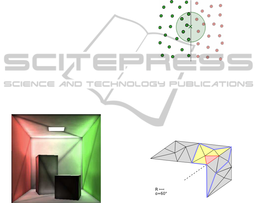
Figure 1: Na¨ıve rendering with the triangle-based photon
mapping method.
However, an additional issue stems from this ap-
proach. Figure 1 shows illumination with photon
mapping when using the subdivision of photon maps.
We see dark edge effects that are related to an incom-
plete integration of the photons close to the edges. At
these points, the knn algorithm searches for photons
in truncated photon maps, resulting in a diminution
of the illumination (see illustration in figure 2). To
avoid this issue, during the first step of the triangle-
based photon mapping, we integrate the photons into
photon maps related to the triangles located nearby.
Two conditions are required to integrate a photon into
a non-intersected triangle: the photon shall be sepa-
rated by a distance not greater than the search radius
and shall have the same space orientation as the trian-
gle. This last requirement prevents the illuminations
of the triangle and of the photon from being too dif-
ferent, which could result in an undesirable bleeding
on the corners.
Figure 2: KNN algorithm only searches nearest neighbors
on the photon map (in green) of the intersected triangle.
A na¨ıve method is to test each photon with all tri-
angles and to add it to the appropriate photon maps.
Despite the fact that this algorithm is carried out in a
precomputation step, the processing time is too long
for a large number of photons and triangles. To over-
come this difficulty, a list of neighboring triangles that
have a similar orientation, is created for each triangle.
Figure 3: In yellow: a group of neighboring triangles with
a similar orientation for a given triangle (in red).
Figure 3 shows the group of neighboring triangles
for the red triangle, in yellow. The blue boundary rep-
resents the triangles close to the red triangle, but too
different in orientation. In our implementation, the
method introduced by D.H. Eberly (Eberly, 2007) is
used to calculate the distance between two triangles.
To compare the orientations between the triangles, we
set a parameter a that defines the maximum value of
the difference between the triangle normal vectors.
Empirically, a value around 60 degrees avoids dark
edge effects and undesirable bleeding on the corners.
When a photon hits a triangle, we add it to the tri-
GRAPP 2012 - International Conference on Computer Graphics Theory and Applications
292
angles listed in the group. During this step, the pho-
tons are not duplicated; only references are stored in
the structure of the maps. With this approach, we de-
crease the number of photons in the maps from sev-
eral million to a few dozen. The quality of the result
remains unchanged (see resulting image on figure 4).
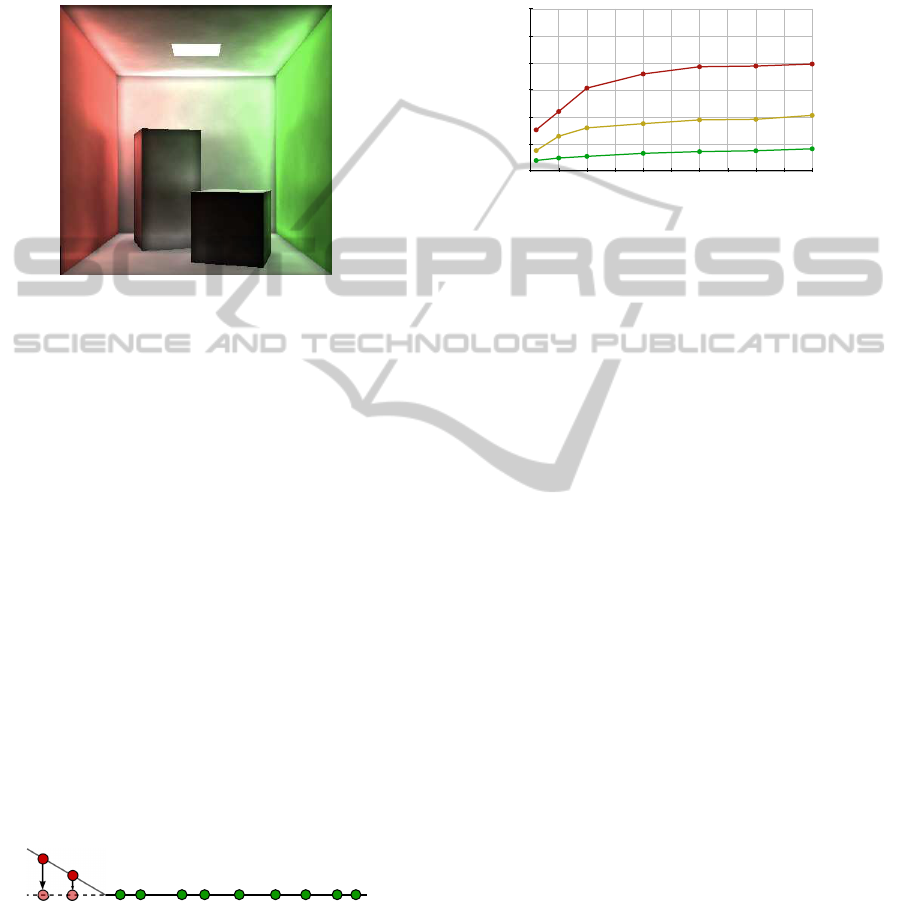
Figure 4: Resulting image with triangle-based photon map-
ping method.
2.2 Two Dimension Structure
In section 2.1, we have shown that the photon maps
are generated for each triangle, and not globally for
the scene. An interesting result of this subdivision
is that the maps contain uniform 2D point clouds in-
stead of a non uniform 3D point cloud with the global
photon map. In the triangle-based photon mapping,
almost all the photons are located on the triangle,
thus they can be represented in triangular coordinates.
However, some photons are not on the plane of the
triangle. In section 2.1, we add photons located on
triangles close to the intersected one. Their position
can not be represented in triangular coordinates for all
the photon maps. In order to use this representation,
we project the considered points on the plane of the
triangle (see figure 5). We use these new coordinates
to store the photons in the data structure. To avoid
wrong results when integrating the illumination, we
use the initial coordinates for the KNN algorithm.
Figure 5: Projection of photons from another triangle (in
red) on two dimensions.
A Photon mapping algorithm usually stores the
photons with a KD tree. Indeed, this structure is the
most effective in the case of a non uniform 3D point
cloud. The new approach of triangle-based photon
mapping, places us in a new case of uniform 2D point
cloud. Specific solutions must be provided for this
new distribution. We use here a 2D uniform grid as
data structure and store the photons in cells. During
the rendering step, the search begins from the closest
cells to the furthest ones until all the nearest photons
are found.
5000 50 100 150 200 250 300 350 400 450
3
0
0,5
1
1,5
2
2,5
Figure 6: Comparison of access time of the knn algorithm
between 3D KD Tree (red), 2D KD Tree (yellow) and 2D
uniform grid (green). X-axis represents the number of pho-
tons.
Figure 6 shows a benchmark for the knn algorithm
between a KD Tree (3D and 2D) and a uniform grid
(2D). With a uniform grid structure, the execution
time is divided by 2 compared to a 2D KD tree, and is
divided by a factor of between 3 and 5 compared to a
3D KD tree.
2.3 Specific Feature for Production
Pipeline
Our works focus on two problems. The first is to de-
crease the execution time of the illumination method
and has been addressed in the previous two sections.
The other problem is related to a specific feature usu-
ally used in a production pipeline after the 3D mod-
eling: the interactive modification of the power of the
light source. In this section, we propose a modifica-
tion of the photon mapping pipeline to provide this
requirement.
H.W. Jensen (Jensen, 2001) considers that the
photon map contain all the information about the pho-
tons, including their energy. Our implementation dif-
fers from that: the starting energy of the sources is
normalized to a value of 1W. The precomputation
time is done with normalized powers for each light
source. These power are included only when the illu-
mination is computed during the rendering step. By
this means, it is possible to interactively modify the
lighting configuration.
2.4 Results
The wide variety of methods and optimizations for
the photon mapping makes it difficult to carry out an
REAL-TIME WALKTHROUGH RENDERING - Speed Improvement of Photon Mapping Algorithm
293

accurate benchmark. Thus, we compare the execu-
tion time obtained by a basic implementation of the
photon mapping with and without our improvements
in some preliminary tests. Both implementations use
GPU and the NVIDIA CUDA framework. Table 1
shows the execution time of the two main steps of the
photon mapping: the KNN algorithm and the integra-
tion of the illumination.
Table 1: Execution time in milliseconds for a scene with
100.000 triangles and 4.000.000 photons. Resolution 500 x
500.
Method KNN Integration Total
Photon mapping 150 140 230
Triangle-based pho-
ton mapping
14 140 154
As shown in figure 1, our method significantly de-
creases the execution time of the KNN algorithm. For
all the process, the improvement is estimated to be
around 40%. There are several reasons for this. First,
the photon maps are smaller with our method: an av-
erage of just 40 photons, with a maximum of 300 for
one map. Another reason is the use of a 2D uniform
grid instead of a 3D KD tree. With our method, the
execution time is not directly dependent on the num-
ber of photons, but on the ratio of the photons to the
number of triangles in the scene.
3 CONCLUSIONS
We have shown in this paper that a subdivision of the
photon map decreases significantly the execution time
of the rendering step. This approach modifies the pho-
ton map structure, changing the mode into two dimen-
sions and decreasing the number of photons.
This new approach provides a result close to real
time rendering for walkthrough. This method ren-
ders images with good accuracy simulating a large
part of the light paths, including the last reflection
on a glossy surface. The end users of this simulation
can also interactively modify the power of the light
sources. These features allow lighting simulation for
production pipelines. We are currently implementing
the method of the triangle-based photon mapping in a
real industrial setting.
ACKNOWLEDGEMENTS
This work was carried out for the VIRTUART project
which is funded by the DGSIS and the PACA region
and has been labeled by the PEGASE cluster.
REFERENCES
Bunnell, M. (2005). Dynamic ambient occlusion and
indirect lighting in GPU Gems 2, pages 223–233.
Addison-Wesley.
Christensen, P., Stollnitz, E., Salesin, D., and Derose, T.
(1996). Global illumination of glossy environments
using wavelets and importance. ACM Trans. Graph.,
15(1):37–71.
Cook, R., Porter, T., and Carpenter, L. (1984). Dis-
tributed ray tracing. Computer Graphics (Proc. SIG-
GRAPH’84), 18:135–45.
Eberly, D. H. (2007). 3D Game Engine Design: A Practical
Approach to Real-Time Computer Graphicsesign: a
practical approach to real-time computer graphics -
2nd edition. ISBN 0122290631. Morgan Kaufmann.
Goral, C., Torrance, K., Greenberg, D., and Battaile, B.
(1984). Modeling the interaction of light between dif-
fuse surfaces. Computer Graphics, 18(3):213–222.
Granier, X., Drettakis, G., and Walter, B. (2000). Fast
global illumination including specular effects. In
Peroche, B. and Rushmeier, H., editors, Rendering
Techniques 2000 (Proceedings of the Eleventh Euro-
graphics Workshop on Rendering), pages 47–59. Eu-
rographics, Springer Wien.
Jensen, H. (1996). Global illumination using photon maps.
Eurographics Rendering Workshop, pages 21–30.
Jensen, H. W. (2001). Realistic Image Synthesis Using Pho-
ton Mapping. A.K. Peters.
Kajiya, J. T. (1986). The rendering equation. Com-
puter Graphics (ACM SIGGRAPH ’86 Proceedings),
20:143–150.
Lai, Y., Fan, S., Chenney, S., and Dyer, C. (2007). Photo-
realistic image rendering with population monte carlo
energy redistribution. EGSR ’07, pages 287–296.
Larsen, B. D. and Christensen, N. J. (2004). Simulating
photon mapping for real-time applications. Rendering
techniques, pages 123–132.
Pajot, A., Barthe, L., Paulin, M., and Poulin, P. (2011).
Combinatorial bidirectional path-tracing for efficient
hybrid cpu/gpu rendering. Computer Graphics Forum,
30(2):315–324.
Ritschel, T., Grosch, T., and Seidel, H. P. (2009). Approx-
imating dynamic global illumination in image space.
Proceedings ACM SIGGRAPH Symposium on Inter-
active 3D Graphics and Games (I3D).
Veach, E. and Guibas, L. (1994). Bidirectional estimators
for light transport. Fifth Eurographics Workshop on
Rendering, pages 147–162.
Wald, I., Mark, W., Hunt, W., G¨unther, J., Parker, S., Bou-
los, S., Shirley, P., and Ize, T. (2007). State of the art in
ray tracing animated scenes. Eurographics 2007 State
of the Art Reports, pages 89–116.
Zhukov, S., Iones, A., and Kronin, G. (1998). An ambient
light illumination model. Rendering Techniques ’98,
pages 45–55.
GRAPP 2012 - International Conference on Computer Graphics Theory and Applications
294
