
STEREO VISION-BASED 3D CAMERA POSE AND OBJECT
STRUCTURE ESTIMATION
An Application to Service Robotics
Sorin M. Grigorescu, Tiberiu T. Cocias¸, Gigel Maces¸anu and Florin Moldoveanu
Department of Automation, Transilvania University of Bras¸ov, Mihai Viteazu 5, 500174, Bras¸ov, Romania
Keywords:
Robot Vision, 3D Reconstruction, Stereo Vision, Volumetric Object Modeling.
Abstract:
In this paper, a robotic pose (position and orientation) estimation and volumetric object modeling system is
proposed. The main goal of the methods is to reliably detect the structure of objects of interest present in a
visualized robotic scene, together with a precise estimation of the robot’s pose with respect to the detected
objects. The robustness of the robotic pose estimation module is achieved by filtering the 2D correspondence
matches in order to detect false positives. Once the pose of the robot is obtained, the volumetric structure of
the imaged objects of interest is reconstructed through 3D shape primitives and a 3D Region of Interest (ROI).
1 INTRODUCTION
In 3D robotic scene perception, there are usually two
types of vision sensors used for acquiring visual in-
formation, that is, stereo vision cameras and range
sensors such as laser scanners or 3D Time-of-Flight
(ToF) cameras (Hussmann and Liepert, 2007). In the
process of stereo vision based 3D perception and ego-
motion estimation, the stereo correspondence prob-
lem has to be solved, i.e. the corresponding feature
points, necessary for 3D reconstruction, have to be ex-
tracted from both stereo images (Brown et al., 2003).
In contrast, stereo vision range sensing devices pro-
vide direct capturing of 3D scenes, delivering a pure
stereo depth image in form of 3D point clouds. In
the case of range sensors, the obtained depth informa-
tion can have different error values, depending on the
sensed surface. This phenomenon makes stereo vi-
sion a more reliable solution for autonomous robotic
systems that operate in real world environments.
Camera pose estimation has been studied within
the Simultaneous Localization and Mapping (SLAM)
context. Using detected visual information, motion
estimation techniques can provide a very precise ego-
motion of the robot. The main operation involved in
stereo based robotic perception is the computation of
the so-called correspondence points used for calculat-
ing the 3D pose of the robot’s camera (Geiger et al.,
2011). The most common features used in this con-
text are points localized through corner detectors such
as Harris. Based on the extracted features, the robot’s
motion can be extracted with the help of estimators
such as the Kalman or Particle Filter.
In the last years, the 3D reconstruction and mod-
eling of objects has become a topic of interest for sev-
eral fields of research such as robotics, virtual real-
ity, medicine, surveillance and industry (Davies et al.,
2008). The main contributions of the presented paper
may be summarized as follows:
1. camera pose and 3D scene structure estimation
pipeline for on-line scene understanding;
2. automatic calculation of a 3D ROI for initializing
the 3D object volumetric estimation algorithm;
3. object grasping points calculation via 3D volu-
metric modeling from generic shape primitives in
highly noisy data (e.g. disparity images).
2 CAMERA POSE ESTIMATION
The block diagram of the proposed vision system is
presented in Fig. 1. The sequence of stereo images
is organized into so-called tracks which include key
features from the imaged scene and geometric con-
straints which are used to solve the pose estimation
problem. One of these elements are the matched 2D
feature points between the left and the right images of
the stereo camera. The accuracy of pose estimation is
directly dependent on the precision of 2D correspon-
dence matching. In order to filter out bad matches,
355
M. Grigorescu S., T. CociaÈ
´
Z T., MaceÈ
´
Zanu G. and Moldoveanu F..
STEREO VISION-BASED 3D CAMERA POSE AND OBJECT STRUCTURE ESTIMATION - An Application to Service Robotics.
DOI: 10.5220/0003819403550358
In Proceedings of the International Conference on Computer Vision Theory and Applications (VISAPP-2012), pages 355-358
ISBN: 978-989-8565-04-4
Copyright
c
2012 SCITEPRESS (Science and Technology Publications, Lda.)
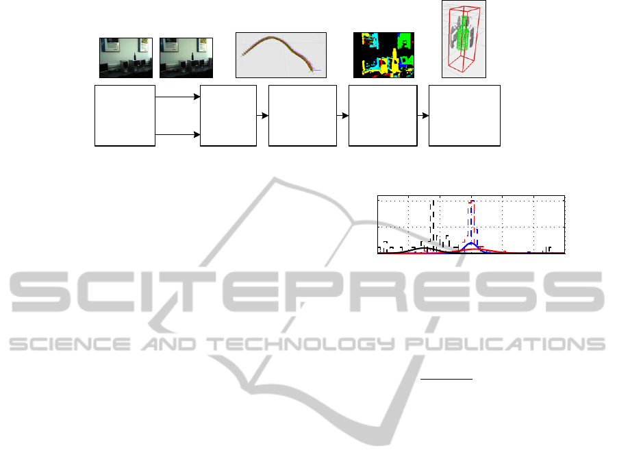
Stereo
Image
Acquisition
Track
Geometry
Estimation
Probabilistic
Filtering and
Camera Pose
Estimation
Object
Segmentation
and
Classification
Right
Image
Left
Image
3D
Volumetric
Modeling and
Object Fitting
Figure 1: Block diagram of the proposed camera pose estimation and object volumetric modeling architecture.
a probabilistic filtering approach, which exploits the
geometrical constraints of the stereo camera, is pro-
posed.
2D feature points have been extracted via the
Harris corner detector, followed by a correspondence
matching using a traditional cross-correlation simi-
larity measure. Secondly, a matching is performed
between the 2D feature points in consecutive stereo
images, that is, between images acquired under ca-
mera poses C(k) and C(k + 1). As convention,
these matches are calculated for the left camera only.
Knowing the 3D positions of the 2D points matched
between adjacent images, the pose of the camera can
be calculated through a Perspective-N-Point (PNP) al-
gorithm (Hartley and Zisserman, 2004).
The obtained pose is further refined using a
Kalman filter. Once the camera pose estimation prob-
lem has been solved, the 3D relation between the
robot and the imaged objects of interest has to be cal-
culated, that is, the establishment of the 3D positions
of the objects grasping points. This process is divided
into two stages. An initial raw object localization is
obtained through a depth image segmentation and ob-
ject classification. Further, the detection of the 3D
grasping points is calculated by statistically fitting a
shape primitive, based on the object classification in-
formation. One of the main contributions of the pa-
per is actually the calculation of an object’s grasping
points through a shape primitive. As it will be ex-
plained, the primitive is independent of a particular
object shape, its fitting being guided by so-called pri-
mitive control points. In other words, a shape can be
fitted to a broad range of objects belonging to that spe-
cific class.
The process of matching stereo features is usu-
ally corrupted by noise and delivers false matches
along with the true correspondences. In order to over-
come this problem, we have chosen to filter out the
bad matches by exploiting the geometrical relations
within a stereo camera. Namely, we take into ac-
count that the majority of the points are true positive.
Hence, we can approximate the probability density of
−30 −20 −10 0 10 20 30
0
0.5
1
Degrees
Slope
Figure 2: Slope filtering models.
the real matches by calculating the slope of the line
connecting the correspondences in two images:
m =
p
R
y
− p
L
y
p
R
x
− p
L
x
, m ∈ M, (1)
where m is the slope between the left and right im-
age points p
L
(x, y) and p
R
(x, y), respectively. Taking
into account a Gaussian probability distribution of the
slope, a Maximum Likelihood Estimator (MLE) has
been used for calculating the parameters of the model,
that is the mean θ
µ
and variance θ
σ
:
b
θ = argmax
θ∈Θ
L(θ|M), (2)
where
b
θ is the obtained maximum likelihood estimate
for the Gaussian Probability Distribution Function
(PDF) p(M|θ
µ
, θ
σ
) describing the distribution of the
lines slope. In Fig. 2, three examples of slope PDF es-
timation can be seen. Using the obtained model, the
feature points can be classified into inliers and out-
liers, as in the classical RANSAC approach.
Once a certain camera pose has been calcu-
lated, it is filtered out using a standard Kalman
filter with a state vector defined as the mea-
sured rotation and translation of the sensor x =
x
i
y
i
z
i
φ
i
ψ
i
θ
i
T
. The transition matrix F
of the Kalman update equation x(k + 1) = F · x(k) +
w(k) encodes a constant camera velocity, with zero
acceleration. One major problem that has to be solved
in depth map fusion is the redundant information
coming from overlapping projected disparity images.
In order to save computation time, we have consid-
ered as valid voxels those ones visible in the newest
images acquired from the stereo camera. An example
VISAPP 2012 - International Conference on Computer Vision Theory and Applications
356
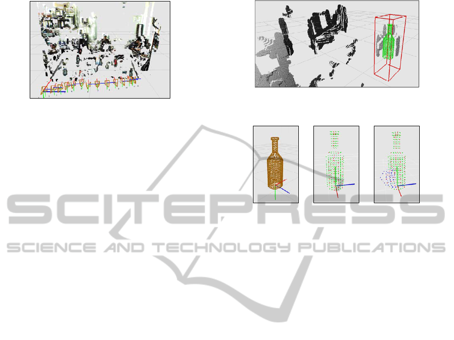
Figure 3: Annotated 3D model from depth maps fusion.
of depth maps fusion within a robotic scene is given
in Fig. 3.
3 3D OBJECT VOLUMETRIC
MODELING
In order to fit a shape primitive over the depth infor-
mation, the imaged objects have to be segmented and
classified. The feature vector used for this operation
is composed of the camera-object distance, described
by the disparity map, and the color distribution of the
objects represented in the HSV (Hue, Value, Satura-
tion) color space. The segmentation result classifies
image pixels into object classes, as seen in Fig. 1.
The 2D segmentation information will be further used
for defining a 3D ROI, which actually initializes the
shape fitting algorithm. This is the starting point used
for deforming the shape primitive in order to fit the
segmented object.
An object ROI is defined in a stereo image pair
as the feature vector [p
L
i
, p
R
i
], i = 1, 2, 3, 4, contain-
ing the four corresponding 2D points in the left and
right images. Knowing the geometry of the stereo ca-
mera, the ROI vector can be reprojected into a vir-
tual 3D environment by calculating the disparity be-
tween p
L
i
and p
R
i
(Brown et al., 2003). The volu-
metric properties of the ROI, namely its 3D volume,
are calculated from the reprojected depth map, that
is, from the 3D distribution of the disparity points
calculated using the robust Block Matching approach
from (Grigorescu and Moldoveanu, 2011). The center
of the ROI over the Z axis is given by the highest dis-
parity points density obtained as a maximization over
the disparity value. The front and back positions of
the ROI are given by the nearest and farthest values in
the disparity. An example of a 3D ROI can be seen in
Fig. 4.
A shape primitive is represented as a Point Dis-
tribution Model (PDM) containing a vector of 3D lo-
cations S related to a common reference coordinate
system:
Figure 4: Reprojected 3D ROI and PDM mesh primitive.
(a) (b) (c)
Figure 5: Object shape primitive fitting example. (a) Shape
primitive. (b) PDM model with control points marked with
red. (c) Deformed shape using a control point (affected
points marked with blue).
x
(i)
∈ S, i = 1, 2, ..., n
p
, (3)
where x is a point on the primitive shape and n
p
the
total number of primitive points. A mesh PDM exam-
ple can be seen in Fig. 5(a). The 3D ROI is used to
position the shape on the center of gravity of the ROI.
Once it is centered, its rotation, translation and scal-
ing is modified through a similarity transform:
X
new
= sR(X
old
+ T ), (4)
where X
old
and X
new
are the old and new 3D positions
of the primitive shape points, R and t are rotation and
translation matrices, respectively, and s represents a
scaling factor.
The last step in the proposed vision system is the
fitting of the object’s primitive on the disparity infor-
mation. This procedure is performed using a set of so-
called control points which regulate the structure of
the shape. Such control points have been introduced
in medical imaging for modeling deformable shapes
such as the hearth (Zheng et al., 2008). To the best
of our knowledge, this is the first application of con-
trol points fitting a shape primitive in a stereo-vision
based system used in visual guided object grasping.
In the PDM from Fig. 5(b), the control points are re-
presented as the red locations. In the example from
Fig. 5(c), the shape is deformed by changing the lo-
cation of one control point. Following a simple linear
transformation, the neighboring points are automati-
STEREO VISION-BASED 3D CAMERA POSE AND OBJECT STRUCTURE ESTIMATION - An Application to
Service Robotics
357

cally translated with respect to the new position of the
control point.
In order to drive the control points to their opti-
mal 3D locations, a relation between the disparity in-
formation contained within the ROI and the control
points on the shape primitive had to be derived. This
is accomplished by estimating the surface normal of
the disparity areas with respect to the control points,
that is, each control points if moved in the direction of
the nearest disparity surface according to its normal.
The advantage of modeling the complete 3D shape
of the objects for grasping purposes plays a crucial
role in the grasping procedure. Namely, if each ob-
ject 3D point is precisely related to the pose of the
robotic system, obtained through the algorithm from
Section 2, then the control precision of autonomous
robots equipped with redundant manipulators is much
higher than for the case when object grasping points
are directly extracted from 2D visual information.
Table 1: Statistical position and orienation errors allong
the three Cartesian axes between the proposed and marker
based 3D camera pose estimation.
X
e
[m; deg] Y
e
[m; deg] Z
e
[m; deg]
Max err. 0.049; 4.2 0.059; 5.6 0.101; 10.1
Mean 0.013; 0.7 0.014; 0.7 0.042; 0.6
Std. dev. 0.021; 2.3 0.02; 2.6 0.064; 5.5
4 PERFORMANCE EVALUATION
The evaluation of the proposed machine vision system
has been performed with respect to the real 3D poses
of the objects of interest. The real 3D positions and
orientations of the objects of interest were manually
determined using the following setup. On the imaged
scene, a visual marker, considered to be the ground
truth information, was installed in such a way that the
poses of the objects could be easily measured with re-
spect to the marker. The 3D pose of the marker was
detected using the ARToolKit library which provides
subpixel accuracy estimation of the marker’s location
with an average error of ≈ 5mm. By calculating the
marker’s 3D pose, a ground truth reference value for
camera position and orientation estimation could be
obtained using the inverse of the marker’s pose ma-
trix. Further, the positions of the camera poses were
calculated using the proposed system. The results
were compared to the ground truth data provided by
the ARToolKit marker.
The marker-less pose estimation algorithm de-
scribed in this paper delivered a camera position and
orientation closely related to the ground truth va-
lues. This correlation can be easily observed when
analysing the statistical error results, given in Tab. 1,
between the two approaches. Namely, for both the
position and orientation, the errors are small enough
to ensure a good spatial localization of the camera, or
robot, and also to provide reliable depth maps fusion.
5 CONCLUSIONS
In this paper a camera pose and 3D object volumet-
ric system for service robotics purposes has been pro-
posed. Its goal is to precisely determine the 3D struc-
ture of the imaged objects of interest with respect to
the pose of the camera, that is, of the robot itself. As
future work, the authors consider the speed enhance-
ment of the proposed system using state of the art par-
allel processing equipment.
ACKNOWLEDGEMENTS
This paper is supported by the Sectoral Oper-
ational Program Human Resources Development
(SOP HRD), financed from the European So-
cial Fund and by the Romanian Government un-
der the projects POSDRU/89/1.5/S/59323 and POS-
DRU/107/1.5/S/76945.
REFERENCES
Brown, M., Burschka, D., and Hager, G. (2003). Advances
in Computational Stereo. IEEE Trans. on Pattern
Recognition and Machine Intelligence, 25(8):993–
1008.
Davies, R., Twining, C., and Taylor, C. (2008). Statisti-
cal Models of Shape: Optimisation and Evaluation.
Springer.
Geiger, A., Ziegler, J., and Stiller, C. (2011). StereoScan:
Dense 3D Reconstruction in Real-time. In IEEE Intel-
ligent Vehicles Symposium, Baden-Baden, Germany.
Grigorescu, S. and Moldoveanu, F. (2011). Controlling
Depth Estimation for Robust Robotic Perception. In
Proc. of the 18th IFAC World Congress, Milano, Italy.
Hartley, R. and Zisserman, A. (2004). Multiple View Geom-
etry in Computer Vision. Cambridge University Press.
Hussmann, S. and Liepert, T. (2007). Robot Vision Sys-
tem based on a 3D-TOF Camera. In Instrumenta-
tion and Measurement Technology Conference-IMTC
2007, Warsaw, Poland.
Zheng, Y., Barbu, A., Georgescu, B., Scheuering, M., and
Comaniciu, D. (2008). Four-Chamber Heart Model-
ing and Automatic Segmentation for 3D Cardiac CT
Volumes Using Marginal Space Learning and Steer-
able Features. IEEE Trans. on Medical Imaging,
27(11):1668–1681.
VISAPP 2012 - International Conference on Computer Vision Theory and Applications
358
