
VISION BASED OBSTACLE AVOIDANCE AND ODOMETERY
FOR SWARMS OF SMALL SIZE ROBOTS
M. Shuja Ahmed, Reza Saatchi and Fabio Caparrelli
Material and Engineering Research Institute, Sheffield Hallam University, Sheffield, U.K.
Keywords:
Obstacle Avoidance, Visual Odometery, Swarm Robotics.
Abstract:
In multi-robotic systems, an approach to the coordination of multiple robots with each other is called swarm
robotics. In swarm robotic systems, small size robots with limited memory and processing resources are
used. Integration of vision sensors in such robots can complicate the design of the robots but at the same
time, a single vision sensor can be used for multiple objectives as it provide rich surrounding information.
As the vision algorithms are normally computationally demanding and robots in swarm systems has limited
memory and processing capabilities, so the requirements of light weight vision algorithms also arises. In
this research, the use of vision sensor information is made for achieving multiple objectives. A solution
to obstacle avoidance, which is the basic requirement as robots move in a cluttered environment and also
odometry which is essential for robot localization, is provided using only visual clues. The approach developed
in this research is computationally less expensive and suitable for small size robots, where processing and
memory constraints limit the use of computationally expensive approaches. To achieve this a library of vision
algorithms is developed and customized for Blackfin processor based robotic systems.
1 INTRODUCTION
Current research in the field of swarm robotics is
largely focused on providing a computer vision so-
lution to guide multiple robots. In most cases small
size robots with limited processing and memory re-
sources, are used. Integration of vision sensor tech-
nology in such systems helps to increase the onboard
intelligence but at a cost of a significant increase in
computational load. The fact that computer vision so-
lutions are computationally very heavy for small size
robots, makes collective achievement of tasks chal-
lenging among swarm of robots. In this research, a
swarm robotic system is considered (shown in fig-
ure 1) in which multiple robotic organisms have the
ability to physically dock, share information, energy
and computational resources with each other and also
can locate the charging points to charge their batter-
ies (Kernbach et al., 2010). These swarms of robots
can self assemble and can artificially create a single
three dimensional robotic organism, which requires
these robots to interact with the environment and also
with each other. These swarms of robots are ex-
pected to perform many different operations in paral-
lel (e.g. docking, communication, scene understand-
ing). Hence, providing vision based senses for guid-
ance and decision making in such robots, naturally re-
quires the development of an efficient and optimized
library of vision processing algorithms. This, in turn,
helps to achieve real time performance on small size
robots. The fact that a vision sensor provides a rich
surrounding information (i.e. a single sensor infor-
mation can be used for multiple purposes), therefore
in this research, this visual information is utilized to
perform multiple tasks that is, obstacle avoidance and
odometery which essentially will help to guide and
localize swarm of robots in a structured environment.
Figure 1: Swarm of robots working collectively (Kernbach
et al., 2010).
For autonomous mobile robotic systems, com-
puter vision provides many solutions to obstacle
avoidance but when it comes to small size robots,
which are also expected to perform many other oper-
115
Shuja Ahmed M., Saatchi R. and Caparrelli F..
VISION BASED OBSTACLE AVOIDANCE AND ODOMETERY FOR SWARMS OF SMALL SIZE ROBOTS.
DOI: 10.5220/0003820701150122
In Proceedings of the 2nd International Conference on Pervasive Embedded Computing and Communication Systems (PECCS-2012), pages 115-122
ISBN: 978-989-8565-00-6
Copyright
c
2012 SCITEPRESS (Science and Technology Publications, Lda.)

ations in parallel, then the number of obstacle avoid-
ance approaches in hand is limited. In (Michels
et al., 2005) an obstacle avoidance technique using a
monocular vision camera together with a laser range
finder is addressed. The testing of the algorithm is
performed in a outdoors highly unstructured environ-
ment but the testing system used is not strictly an em-
bedded system as all the image processing is done on
a development platform so the chances of techniques
not meeting the real time constraints were also possi-
ble. Another common approach, addressed in (Chao
et al., 1999) (Borenstein and Koren, 1985) (Boren-
stein and Koren, 1988), is based on edge detection.
In this method, the algorithm determines the vertical
edges of the obstacle and helps robots to move around
the edges without colliding against the obstacles. In
(Pratt, 2007), the Lucas-Kanade optical flow based al-
gorithm is used for MAVs (Micro Aerial Vehicles)
in urban environment. Similarly, in (Souhila and
Karim., 2007) Horn and Schunck’s optical flow based
algorithm is used in autonomous robots. Using opti-
cal flow, image velocity vectors are determined which
can be split into translational and rotational compo-
nents. From the translational component, the time
to contact information for the obstacle can be calcu-
lated which helps in taking necessary actions. An-
other area of research in computer vision and robotics
targeted in this study is the development of efficient
visual odometery algorithm for small size robots. In
(Maimone et al., 2007), a feature tracking based mo-
tion estimation approach is presented to obtain visual
odometery information using stereo images captured
from NASA’s Mars Exploration Rovers (MERs) in a
highly unstructured environment. In (Campbell et al.,
2005), visual odometry results using optical flow in-
formation are presented when the ground robot is
moved on a varying terrain including indoor and out-
door environments. The errors reported were 3.3%
and 7.1% when the robot is moved on a carpet (high
friction) and polished concrete, respectively. Simi-
larly, in (Milford and Wyeth, 2008) (Kyprou, 2009) a
scanline intensity based simple algorithm to obtain vi-
sual odometry is presented. The odometry error with
this algorithm can be large but, in spite of this, no-
table results are achieved when the odometry infor-
mation is used with a SLAM (Simultaneous Localiza-
tion and Mapping) system. A relevant research done
in (Schaerer, 2006) addresses the use of line features
tracking. Using Hough Transform lines are tracked
for obtaining the distance and orientation information.
Another algorithm presented in (Younse and Burks,
2007) is based on feature tracking using the Lucas-
Kanade algorithm. It also utilizes the information ob-
tained from camera modelling (intrinsic and extrin-
sic parameters) to precisely locate the new position
of the vehicle. The average translation error reported
when the vehicle moved 30 cm is 4.8 cm and the aver-
age rotation errors were 1 and 8 degrees for a 45 and
180 degrees rotation, respectively. This approach per-
formed poorly at high rotation rate as features could
move out of the search window. Hence, in the field
of autonomous robotics, many approaches to visual
odometery (Maimone et al., 2007) (Nistar et al., 2006)
(Howard, 2008) using high speed systems are ad-
dressed and notable results are achieved. The high
computational cost of these algorithms makes them
unsuitable for swarms of small size robots. However,
further advances in research to provide fast and reac-
tive solutions to these problems is still required. In
the following sections, the methods used to perform
vision based obstacle avoidance and odometery are
detailed in section 2. In section 3, the results obtained
when the experiments performed in the in-door en-
vironment, are presented. Conclusions are drawn in
section 4.
2 METHODOLOGY
The hardware is an important factor which strongly
influences the methods adapted to solve the problem
at hand. The onboard processing on the robot (shown
in Figure 1) was achieved using a high performance
16/32-bit Blackfin BF537E processor. uClinux (mi-
cro controller linux), which is a powerful operating
system customized for embedded systems, was used
as the onboard operating system. Code compilation
was done using GNU cross compilers on a Linux
based development platform. For the testing and
demonstration of the developed vision algorithms,
SRV robot by Surveyor Corporation was used. Before
proceeding to the complex vision algorithms such as
obstacle avoidance and visual odometry, a library of
basic vision algorithms was developed. This library
was optimised especially for the Blackfin processor
architecture. It includes image conversion to differ-
ent formats (such as YUV to colour image), colour
to greyscale image, image gradient using Sobel and
Canny operator, region growing based image segmen-
tation, colour blob detection, feature detection using
Harris algorithm, cross-correlation based algorithm to
solve the feature correspondence problem, image ero-
sion and dilation algorithms. It was decided to add
more algorithms as the need arises. In the following
sections, the approaches used to perform vision based
obstacle avoidance and range of visual odometry al-
gorithms developed are discussed in detail.
PECCS 2012 - International Conference on Pervasive and Embedded Computing and Communication Systems
116
2.1 Obstacle Avoidance
There are many ways to accomplish obstacle avoid-
ance but efforts are being made to come up with an al-
gorithm with less computational complexity. For ex-
ample, algorithms with more floating point operations
have more computational complexity and execution
time. The Blackfin processor used here is a fixed point
processor and can not perform floating point opera-
tions efficiently so algorithms with less floating point
operations are preferred. Finally, the algorithms are
customized to exploit the fixed point Blackfin archi-
tecture as suggested in (Lukasiak et al., 2005). Two
obstacle avoidance algorithms, where one was based
on segmentation and the other utilized the optical flow
information, are presented.
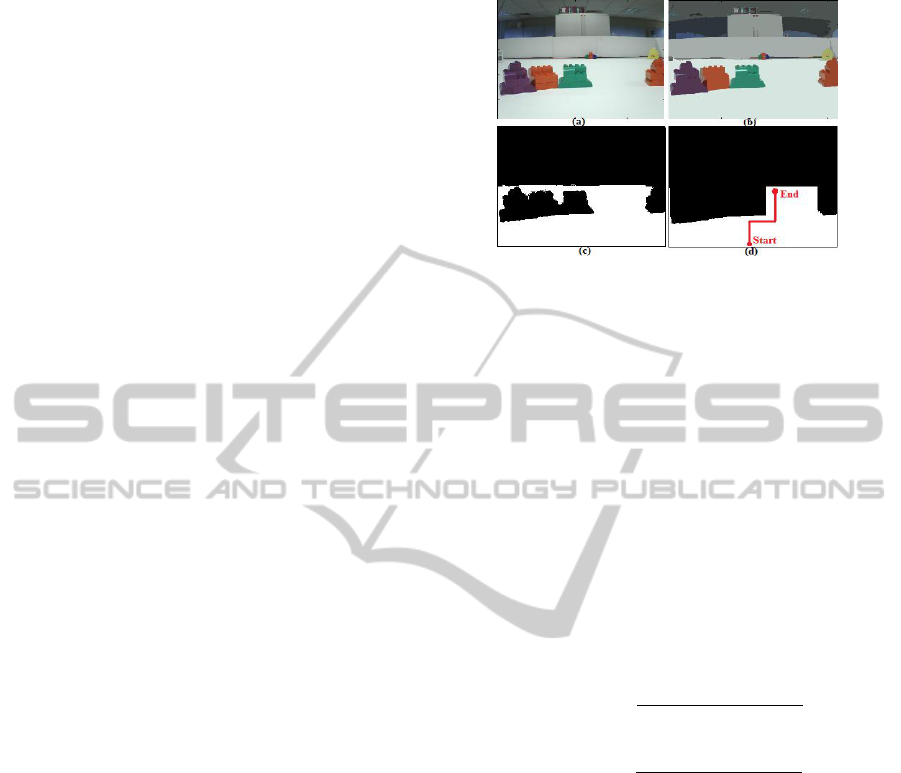
2.1.1 Segmentation based Obstacle Avoidance
To explain the concept of segmentation based obstacle
avoidance, we considered the image in Figure 2 show-
ing a couple of obstacles. Some assumptions were
made that the robot is placed on a flat ground with
camera slightly tilted down. In Figure 2b, segmenta-
tion result is shown. To determine ground region, one
assumption can be that the biggest segmented region
is from ground but it may be false when the robot is in
front of a big obstacle which result the biggest region.
In the current implementation, the speed of the robot
is set to guarantee that it is not very close to the obsta-
cle and the region covering the middle bottom of the
image is considered to be the ground region. Some-
times, while turning, there is a possibility that the ob-
stacle is very close to the robot. In this scenario, the
robot can collide with it. To overcome this problem,
the robot keeps track of the intensity of ground region
in the last few frames. A sudden change in the inten-
sity helps robot to determines the presence of an ob-
stacle. Following this approach, the isolated ground
region is shown in Figure 2c (Total Ground Map).
To determine the ground map visible to the robot, the
’Total Ground Map’ is filled vertically up with white
pixels until the obstacle boundary is detected and the
rest of the pixels to the top are filled with black pix-
els. The same is done for all the columns. The im-
age is finally dilated for refinement. The final visible
ground map is shown in Figure 2d. To determine the
presence of an obstacle, if from the centre bottom of
the final ground map, the number of white pixels are
greater than 30 in the vertical direction, then the robot
goes straight. It also checks for enough space from
left and right direction. If white pixels are less than
30, then the algorithm checks from which side it has
more clearance and turn the robot in that direction. In
Figure 2d an expected robot trajectory is shown.
Figure 2: The step by step processing of segmentation based
obstacle avoidance algorithm.
2.1.2 Optical Flow based Obstacle Avoidance
Another approach to obstacle avoidance is based on
Horn and Schunck (Horn et al., 1993) optical flow
information and is inspired from the work done in
(Souhila and Karim., 2007). Horn and Schunck de-
rived equations that relate image brightness at a point
to the motion of brightness pattern. For this purpose,
partial derivatives of the image brightness in x (E
x
), y
(E
y
) directions and in time space (E
t
) are obtained.
These partial derivatives are used to obtain optical
flow vectors u and v in x and y direction, respectively.
These vectors are obtained using the following recur-
sive equations.
u
n+1
= ¯u
n
−
E
x
[E
x
¯u
n
+ E
y
¯v
n
+ E
t
]
α
2
+ E
2
x
+ E
2
y
(1)
v
n+1
= ¯v
n
−
E
y
[E
x
¯u
n
+ E
y
¯v
n
+ E
t
]
α
2
+ E
2
x
+ E
2
y
(2)
Where α is a weighting factor and ¯u
n
and ¯v
n
are local
averages. These recursive equations performs many
floating point operations and it was possible to pro-
cess only one frame in 2 seconds. For faster exe-
cution, part of algorithm was coded to perform dec-
imal operations. For this purpose, the necessary pre-
cision was determined. For example, for a number
1.3678987, to keep precision upto four decimal point,
the number will be multiplied with 10
4
and rest of
computation will be done in decimal point format.
Where decimal format did not work, fixed point im-
plementation was adopted. This made it possible to
process 3.5 frames per second. Now to determine
the presence of the obstacle, the image was divided
into left and right parts and every time the magni-
tudes of the optical flow vectors were calculated for
these parts. If the sum of these magnitudes exceeds
some predefined thresholds, it was assumed that the
obstacle is in front of the robot and it turns in the di-
VISION BASED OBSTACLE AVOIDANCE AND ODOMETERY FOR SWARMS OF SMALL SIZE ROBOTS
117
rection which produces less magnitude of the optical
flow vectors (i.e. more clearance).
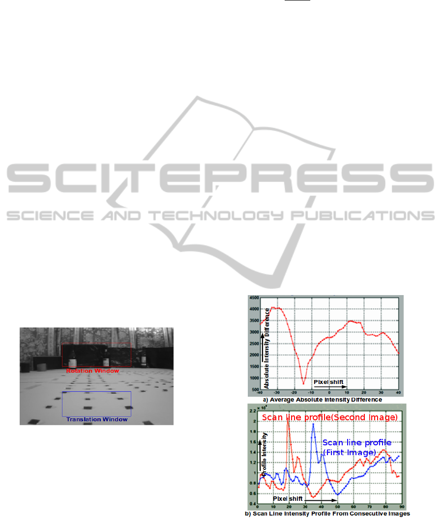
2.2 Visual Odometry
Different approaches to perform visual odometry
were implemented and compared with each other. Ini-
tially an algorithm, using scan line intensity profile
formed by sub images, for obtaining the visual odom-
etry information, was adapted. This scanline profile
idea was also adapted in (Pomerleau, 1997) for devel-
oping visual steering system and it can also be found
in (Milford and Wyeth, 2008) where visual odometry
based on single camera was used for SLAM system.
The scan line profile is a one-dimensional vector ob-
tained by summing the intensity values in each pixel
column of the selected part of the image and then nor-
malized. This vector profile is compared with the
other profiles obtained from the consecutive images
to extract the rotation and forward distance covered
information. Figure 3 shows the top and bottom win-
dow images which are used to determine rotation and
forward speed, respectively. The scanline idea for ob-
taining the speed was found very sensitive to lighting
conditions and was discarded. So, to obtain the dis-
tance covered information, two approaches were ex-
amined, i.e. the feature tracking using Lucas-Kanade
(Lucas and Kanade, 1981) and feature matching us-
ing Normalized Cross Correlation (Lewis, 1995) al-
gorithm. These are explained below.
Figure 3: Image parts for rotation and translation cues.
2.2.1 Rotation Estimation
Rotation information is obtained by comparing the
scan line intensity profile vectors from two consec-
utive images captured by the vision system. In Fig-
ure 4b, the scan line intensity profiles from two con-
secutive images are shown. For comparison between
the profiles, the average absolute intensity difference
f (t) was calculated between the two scanline vectors
while a relative shift of the vectors with respect to
each other is also performed. The following equation
is used to achieve this task.
f (t, V
j
, V
k
) =
1
w − |t|
(
w−|t|
∑
n=1
|V
j
n+max(t,0)
−V
k
n−min(t,0)
|)
(3)
where V
j
and V
k
are the intensity profile vectors to
be compared (shown in red and blue colours, respec-
tively, in Figure 4b), t is the amount of pixel shift per-
formed between the two profiles, and w is the width
of the windowed image. In Figure 4a, the absolute in-
tensity differences graph, when one profile vector is
shifted over the other, is shown. The pixels shift p
s
were obtained by determining the value t which min-
imizes the function f (t) for the vectors V
j
and V
k
:
p
s
= min
t∈|ρ−w,w−ρ|
f (t, V
j
, V
k
) (4)
The selection of offset ρ was made such that there
was enough overlap between the two profiles. The
values used for w and ρ were 88 and 40, respectively.
For the two profiles shown in Figure 4b , the value of
pixel shift p
s
obtained is 15 pixels in the left direction
from the center of image. This pixel shift is multiplied
by gain factor α to perform conversion into an angular
shift value ∆θ. The value of α can be obtained empir-
ically or by using the camera’s intrinsic parameters:
∆θ = αp
s
(5)
Figure 4: a) Average intensity difference when one profile
shifted over the second. b) Two scanline profiles.
PECCS 2012 - International Conference on Pervasive and Embedded Computing and Communication Systems
118
2.2.2 Translation Estimation using
Lucas-Kanade Feature Tracking
The translation estimation algorithm is divided into
two tasks. The first is to detect salient features in the
image and the second is the features tracking. For
feature detection, Harris feature detection (Harris and
Stephens, 1988) algorithm was implemented. The
features detected were then tracked in the following
images by the Lucas-Kanade tracking algorithm. The
basic idea of the Lucas-Kanade (Lucas and Kanade,
1981) tracking algorithm is the following. Let, I
1
and
I
2
be two images and u be a feature detected on im-
age I
1
, where u = [x, y] and I
1
(u) =I
1
(x, y). Then, the
goal of the Lucas-Kanade tracking is to find the loca-
tion v = u + d on the second image I
2
such that I
1
(u)
and I
2
(v) are similar. Let, d be the image velocity
vector at point u. The next step is to define a neigh-
bourhood around feature u (i.e. w
x
and w
y
in x and y
directions), where similarity analysis between u and v
can be made. Then, vector d can be defined as the one
which minimizes the following residual function:
∈ (d) =
u
x
+w
x
∑
x=u
x
−w
x
u
y
+w
y
∑
y=u
y
−w
y
[I
1
(x, y) − I
2
(x + d
x
, y + dy)]
2
(6)
After obtaining the velocity vector, the new fea-
ture location can be determined and tracked. For
odometry, the average shift made by the feature in y
direction (after multiplying by scale factor) is used to
determine the translation and the shift in x direction is
used for the small rotation information. To measure
large rotation, scan line algorithm is used in parallel.
2.2.3 Translation Estimation using Normalised
Cross Correlation Feature Matching
Another approach developed in this work was based
on Normalised Cross Correlation matching of salient
features. The features are detected in two images us-
ing the Harris algorithm. Matching and correspon-
dence between the features is performed using nor-
malised cross correlation algorithm. In this algorithm,
to perform feature matching, a small template is taken
around each feature in one image and is matched with
the other image within a predefined search window.
The basic equation used to perform cross correlation
matching is given below.
C(m, n) =
∑
x,y
bI(x, y) −
¯
I
m,n
c[t(x − m, y − n) −
¯
t]
[
∑
x,y
[I(x, y) −
¯
I
m,n
]
2
∑
x,y
[t(x − m, y − n) −
¯
t]
2
]
0.5
(7)
In this equation, I(x,y) is the image and t(x,y) is the
target template (i.e. template around feature),
¯
t is the
mean of the template and
¯
I
m, n
is the mean of the im-
age. Once corresponding features are identified, then
the average pixel shift in x and y direction is used
to determine the rotation and translation, respectively.
For large rotation, scan line works in parallel.
3 RESULTS
This section is dedicated to the results. It includes
obstacle avoidance using segmentation/optical flow
information and visual odometery results from scan
line based rotation, Lucas-Kanade tracking and nor-
malised cross correlation based translation algorithm.
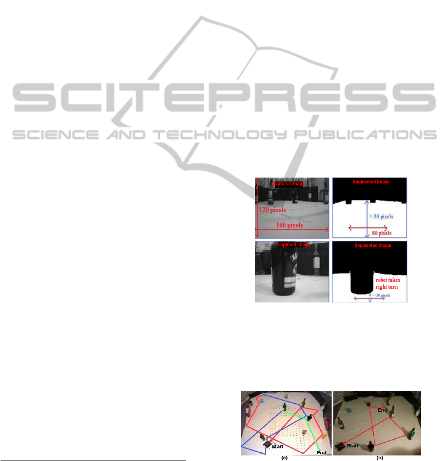
3.1 Obstacle Avoidance
To test this algorithm, a test platform was devel-
oped. Obstacles were placed on uniform white sur-
face. Some processed images are shown in Figure 5.
When the algorithm finds that the white pixels to the
obstacle boundary are less than 30, then it determines
which side gives more clearance and turns in that di-
rection. Factor 30 pixels is determined empirically.
Figure 5: Segmentation based obstacle avoidance.
Using this algorithm, many tests were performed.
One of the path followed by the robot is shown in
Figure 6a. The maximum frame rate achieved with
this approach is 2.46 frames per second.
Figure 6: (a) Segmentation result (b) Optical flow result.
A trajectory made by the robot using optical flow
VISION BASED OBSTACLE AVOIDANCE AND ODOMETERY FOR SWARMS OF SMALL SIZE ROBOTS
119
algorithm, is shown in Figure 6b. In Figure 7, the op-
tical flow information generated from the two consec-
utive images, when the robot was moving in forward
direction, is shown. A zoomed-in version of the opti-
cal flow field is also shown. The optical flow vectors
obtained are in the correct direction (i.e. opposite to
the direction of motion) but there are some vectors in
random directions and act as noise. The maximum
frame rate achieved with this approach is 3.5 frames
per second.
Figure 7: Optical flow field between 2 consecutive images.
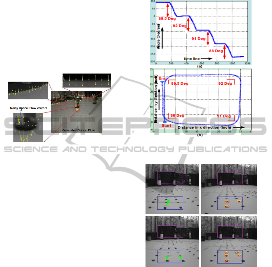
3.2 Visual Odometry
For visual odometry, the scanline algorithm was used
for getting the rotation estimates. In Figure 8, the re-
sults obtained, when the robot was making a square
trajectory, are shown. The robot moved equal dis-
tances after every 90 degrees turn. In Figure 8a, the
angle measurement obtained from the visual odome-
try is shown. Robot has taken 89.5, 92, 91 and 88 de-
grees turns in place of 90 degrees turn. The resultant
square trajectory is also shown in Figure 8b. This ro-
tation and translation measurements are obtained us-
ing the scanline profile based algorithm. The scanline
algorithm for translation is found very sensitive to the
lighting conditions. It gives totally different transla-
tion estimates in a different environment. So here, ac-
curacy achieved in rotation using scanline is focused.
To obtain the accuracy in translation estimates, the
feature based approach was used. For features de-
tection, black marks were made on the ground sur-
face. In Figure 9, some of the results obtained from
the Lucas-Kanade tracking (left column) and feature
matching results from the normalised cross correla-
tion algorithm (right column) are shown.
To test feature based translation estimation algo-
rithm, two tests were performed. In Figure 10a, the
visual odometry results obtained from test 1, when
the robot was moved 36 inches forward, took a 90 de-
gree right turn and then moved 11 inches, are shown.
In the results obtained from the Lucas-Kanade algo-
rithm, the robot moved 38.6 inches forward and 10
Figure 8: Angle information and the actual trajectory ob-
tained from visual odometry for square trajectory.
Figure 9: Lucas-Kanade and Normalised cross correlation
feature tracking and matching results.
inches after taking a right turn. According to the mea-
surements obtained using the cross correlation based
algorithm, the robot moved 38.7 inches forward and
then 9.5 inches after taking a right turn. Both of these
measurements are very close to the actual trajectory
made by the robot. Similarly, Figure 10b shows the
results obtained from test 2 when the robot moved 36
inches forward, took a 90 degree left turn and then
moved 9.5 inches. According to the measurements
obtained using the Lucas-Kanade algorithm, the robot
moved 37.4 inches forward and 8.3 inches after taking
a left turn. According to the cross correlation based
PECCS 2012 - International Conference on Pervasive and Embedded Computing and Communication Systems
120
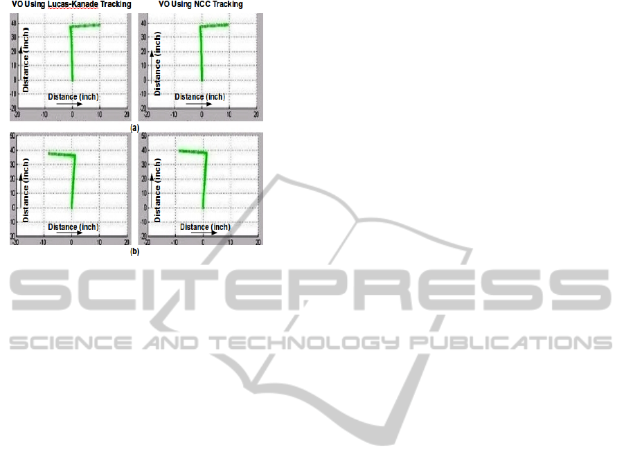
Figure 10: Visual odometry (a) test 1 (b) test 2.
algorithm, the robot moved 39.4 inches forward and
8.6 inches after taking a left turn.
4 CONCLUSIONS
In this research, vision algorithms for a Blackfin
based small size robotic system have been developed.
For obstacle avoidance, a slightly slower frame rate
was achieved but it can be improved by implementing
the computationally expensive sections of the code in
assembly language. For visual odometry, the Lucas-
Kanade based approach has provided good results
when tested using Matlab. But it is found that, in case
of features lost, some time it provides less accuracy
than expected. It is concluded that, the use of scan
line based rotation information with the feature based
approach provide an efficient solution to visual odom-
etry but at the same time, it can be easily deceived if
the robot come close to a moving object such as an-
other robot. To overcome this, information from vi-
sual odometry may be fused together with the wheel
odometry to determine whether the robot was actually
moved or object in the environment moved.
ACKNOWLEDGEMENTS
This research was funded by European Commission
Seventh Framework Programme FP7/2007-2013 re-
search project REPLICATOR.
REFERENCES
Borenstein, J. and Koren, Y. (1985). A mobile platform for
nursing robots. In IEEE Transactions on Industrial
Electronics, Vol. 32, No. 2.
Borenstein, J. and Koren, Y. (1988). Obstacle avoidance
with ultrasonic sensors. In IEEE journal of robotics
and automation, vol. ra-4, no. 2.
Campbell, J., Sukthankar, R., Nourbakhsh, I., and Pahwa,
A. (2005). A robust visual odometry and precipice
detection system using consumer-grade monocular vi-
sion. In Proc. ICRA, Barcelona, Spain.
Chao, M., Braunl, T., and Zaknich, A. (1999). Visually-
guided obstacle avoidance. In 6th International Con-
ference on Neural Information Processing ICONIP.
Harris, C. and Stephens, M. (1988). A combined corner and
edge detector. In Proceedings of the 4th ALVEY vision
conference, University of Manchester, England.
Horn, Berthold, K. P., and Schunck, B. G. (1993). Deter-
mining optical flow. In Artificial Intelligence: 81-87.
Howard, A. (2008). Real-time stereo visual odometry for
autonomous ground vehicles. In IEEE/RSJ Interna-
tional Conference on Intelligent Robots and Systems.
Kernbach, S., Scholz, O., Harada, K., Popesku, S., Liedke,
J., Raja, H., Liu, W., Caparrelli, F., Jemai, J., Hav-
lik, J., Meister, E., and Levi, P. (2010). Multi-robot
organisms: State of the art. In ICRA 2010 Workshop
Modular Robots: State of the Art.
Kyprou, S. (2009). Simple but effective personal localisa-
tion using computer vision. In MEng Report. Depart-
ment of Computing, Imperial College London.
Lewis, J. P. (1995). Fast template matching. In Vision In-
terface, p. 120-123.
Lucas, B. D. and Kanade, T. (1981). An iterative image
registration technique with an application to stereo vi-
sion. In IJCAI.
Lukasiak, R., Katz, D., and Lukasiak, T. (2005). Enhance
processor performance in open-source applications. In
Analog Dialogue 39-02.
Maimone, M., Cheng, Y., and Matthies, L. (2007). Two
years of visual odometry on the mars exploration
rovers. In Journal of Field Robotics. Special Issue:
Special Issue on Space Robotics. Volume 24, Issue 3.
Michels, J., Saxena, A., and Andrew, Y. (2005). High speed
obstacle avoidance using monocular vision and rein-
forcement learning. In Proceedings of the 22nd Inter-
national Conference on Machine Learning.
Milford, M. and Wyeth, G. (2008). Mapping a suburb with
a single camera using a biologically inspired slam sys-
tem. In Robotics, IEEE Transactions on , vol.24, no.5,
pp.1038-1053, Oct. 2008.
Nistar, D., Naroditsky, O., and Bergen, J. (2006). Visual
odometry for ground vehicle applications. In Journal
of Field Robotics, Volume 23.
Pomerleau, D. (1997). Visibility estimation from a mov-
ing vehicle using the ralph vision system. In In IEEE
Conf. Intelligent Transportation Systems.
Pratt, K. (2007). Smart sensors for optic flow, obstacle
avoidance for mavs in urban environments. In Inter-
national Journal of Advanced Robotic Systems.
VISION BASED OBSTACLE AVOIDANCE AND ODOMETERY FOR SWARMS OF SMALL SIZE ROBOTS
121

Schaerer, S. S. (2006). Practical visual odometry for small
embedded systems. In Master’s Thesis, Department
of Electrical and Computer Engineering, University
of Manitoba.
Souhila, K. and Karim., A. (2007). Optical flow based robot
obstacle avoidance. In International Journal of Ad-
vanced Robotic Systems.
Younse, P. J. and Burks, T. F. (2007). Greenhouse robot
navigation using klt feature tracking for visual odom-
etry. In International Commission of Agricultural En-
gineering. CIGR E-Journal Volume 9.
PECCS 2012 - International Conference on Pervasive and Embedded Computing and Communication Systems
122
