
SUPPORT FOR ROBOT DOCKING AND ENERGY FORAGING
A Computer Vision Approach
M. Shuja Ahmed, Reza Saatchi and Fabio Caparrelli
Material and Engineering Research Institute, Sheffield Hallam University, Sheffield, U.K.
Keywords:
Vision based docking, Blob detection, Multi-robotics.
Abstract:
Swarm robotics deals with the multi-robot coordination for achieving the common objective. The latest re-
search in this field focuses on more complicated domain of problem where swarms of robots may require to
physically dock together to achieve the goal. The physical docking may be required to move over a big obsta-
cle or also to perform precise physical connection with certain objective e.g. battery charging. In this research,
the information from vision sensor is considered to provide support for performing precise physical docking.
The robotic system considered in this study requires the robots to autonomously recharge their batteries for
guaranteeing long term operations and also to perform complicated physical docking for which precision is
necessary. A very simple but effective solution based on LEDs, used in a specified pattern on docking station,
is adopted. The approach presented in this research is found computationally less expensive so is suited to be
used with swarm robotic system which uses small robots with limited memory and processing resources.
1 INTRODUCTION
In swarm robotic systems, where multiple robots try
to achieve tasks collectively, the robots may require to
work continuously for several hours to achieve a com-
mon goal. The biggest constrained to the continuous
operation is the limited on-board power. If robot runs
out of battery and leave a mission while performing
collective task, then it can result in mission failure.
One way is the manual charging or human interven-
tion for recharging robot, but this may be not possible
in hazardous environments (e.g building infected with
virus or factory with gas leak). In manual charging, as
the human assistance is always required so this also
prevents the long term autonomous robotic operations
which may continue for several hours. The power
constraints in robotics introduces the concept of au-
tonomous battery recharging by robots. This requires
the robots to determine when they are running out of
battery charging, look for the energy points and dock
to them for battery recharging purposes. In swarm
robotic systems, as many robots are involved, so the
provision of limited charging points may also require
the robots to dock to each other for energy sharing.
The capabilities of energy sharing and battery charg-
ing will help the robots in a swarm to ensure long term
autonomy and also to show efficient energy utilization
by sharing energy resources with each other.
Figure 1: Swarm of robots (Kernbach et al., 2010).
In this research, a swarm robotic system is consid-
ered (shown in Figure 1) in which multiple robotic or-
ganisms have the ability to physically dock, share in-
formation, energy and computational resources with
each other to perform certain tasks collectively (Kern-
bach et al., 2010). Every robot in the swarm also
struggles for survival by searching for energy points
and autonomously recharging its battery to guarantee
its participation to contribute in a long term opera-
tion. If robots units find charging points not in access,
then they can use their docking feature to physically
join with each other and become a single three di-
mensional robotic organism so that access to charging
points may be achieved. This study presents the re-
search done to facilitate the autonomous robot dock-
ing and locating energy points for battery recharg-
ing purposes. For precise docking, information from
infra-red sensor may be relied upon, but from dis-
123
Shuja Ahmed M., Saatchi R. and Caparrelli F..
SUPPORT FOR ROBOT DOCKING AND ENERGY FORAGING - A Computer Vision Approach.
DOI: 10.5220/0003820801230128
In Proceedings of the 2nd International Conference on Pervasive Embedded Computing and Communication Systems (PECCS-2012), pages 123-128
ISBN: 978-989-8565-00-6
Copyright
c
2012 SCITEPRESS (Science and Technology Publications, Lda.)

tance, the short range of infra-red sensor does not al-
low the robots to identify the battery charging points.
Here, the power of computer vision technology to
help robots to look for the charging points and facili-
tate the robot docking operation is addressed.
2 STATE OF THE ART
Autonomous robot recharging, also known as en-
ergy foraging, is an area of research in the field of
swarm robotics which is leading to provide solutions
to perform long term operations by multiple robots
and is been addressed by a number of researchers
in this field. In (Schmickl et al., 2008), a collec-
tive energy foraging is addressed in which multiple
robots try to look for energy resources collectively.
Search of energy resources can be performed using
the information only from vision sensor (REPLICA-
TOR, 2008). In (SYMBRION, 2008) (REPLICA-
TOR, 2008), swarm robotic systems are described
which can look for energy resources individually or
can also share energy resources by docking to each
other. For battery recharging purposes, physical dock-
ing with energy point is essentially required and re-
searchers have used different approaches to detect
these docking stations. In (Silverman et al., 2002),
a robot equipped with high performance system, laser
range finder and vision sensor is used to provide so-
lution to the robot recharging problem. A cone shape
physical docking mechanism is provided. To facili-
tate the detection of docking port using vision sensor,
an orange piece of paper is used as a landmark near
the port. This landmark helps the robot to locate the
charging point and correct its orientation. Laser bea-
con used above the charging point also provides major
help to guide robot to reach the charging point. This
is an expensive solution to battery recharging problem
considering the targeted system in which robots with
limited resources are used. In (Dunbabin et al., 2008),
a colour segmentation approach is used to achieve the
coordinated vision based docking of an autonomous
surface vechicle with the autonomous underwater ve-
hicle (AUV) while performing the recovery of AUV.
Multiple processors are used on-board to perform this
task. One processor is used for vehicle control and the
second is used to perform vision processing as com-
putationally expensive vision based algorithms were
used. This solution can not be used in swarm robotic
environment, where each robot has a single processor
to perform multiple tasks in parallel. In (Low et al.,
2007), a wheel mobile robot is used for vision based
docking. For the detection of docking port, a black
cardboard was used near to it. A corner detection al-
gorithm was used to detect the corners of cardboard
and to perform the robot alignment with the dock-
ing port. To achieve this, a high performance system
is used on-board to perform vision processing opera-
tions. As mentioned before, for autonomous battery
recharging, physical docking is required and this con-
cept also let the researchers to visualise robotic sys-
tems in which multiple robots dock together to be-
come a single robot. In (Zhang et al., 2011), a mod-
ular self-reconfigurable robotic system is considered
and infrared sensor based robot docking is addressed,
but the limited range of infrared sensor does not al-
low the robots to detect each other from large dis-
tance. The use of IR together with vision informa-
tion is also addressed by several researchers. In (Will
and Shen, 2001) (Nagarathinam et al., 2007) only IR
sensor information relied on to perform docking. The
use of only vision support for docking is presented in
(Bonani et al., 2005) (Yamakita et al., 2006) (Trianni
et al., 2009) in which swarm of robots dock together
to drag heavy objects. This is an example of a swarm
robotic system which addresses the problem where
an object appears to be too big that a single robot
alone can not move it and requires the support from
other robots. The docking ports used on these robots
are very simple and does not required precise alig-
ment. In (Kurokawa et al., 2006) (Sastra et al., 2007),
a more complicated docking mechanism is presented
which uses help from IR and vision sensor to attach
two robot with each other.
3 METHODOLOGY
As discussed before, in the considered system, the
robots have an ability to dock with each other. For
this purpose, a complicated mechanics to enable hard-
ware docking is addressed in (Kernbach et al., 2010)
and is also shown in Figure 2a. This system requires
precise alignment of the robot units to perform suc-
cessful docking. Infra-red sensors can provide preci-
sion but their short range does not let this approach
to be effective when robots are far from each other.
To easily identify the robot docking port using vision,
four LEDs are mounted on the port as shown in Fig-
ure 2a. The robot will turn ON its LEDs to request
the other robots to start docking operation. For the
demonstration of the algorithm providing vision sup-
port for docking, SRV robot by Surveyor Corporation
was used as it uses the same Blackfin processor which
is used in robot units shown in Figure 2a. To represent
the other robots docking port, a white box with four
Red LEDs mounted on it was used. Here, the target is
to develop light weight vision algorithm which can
PECCS 2012 - International Conference on Pervasive and Embedded Computing and Communication Systems
124
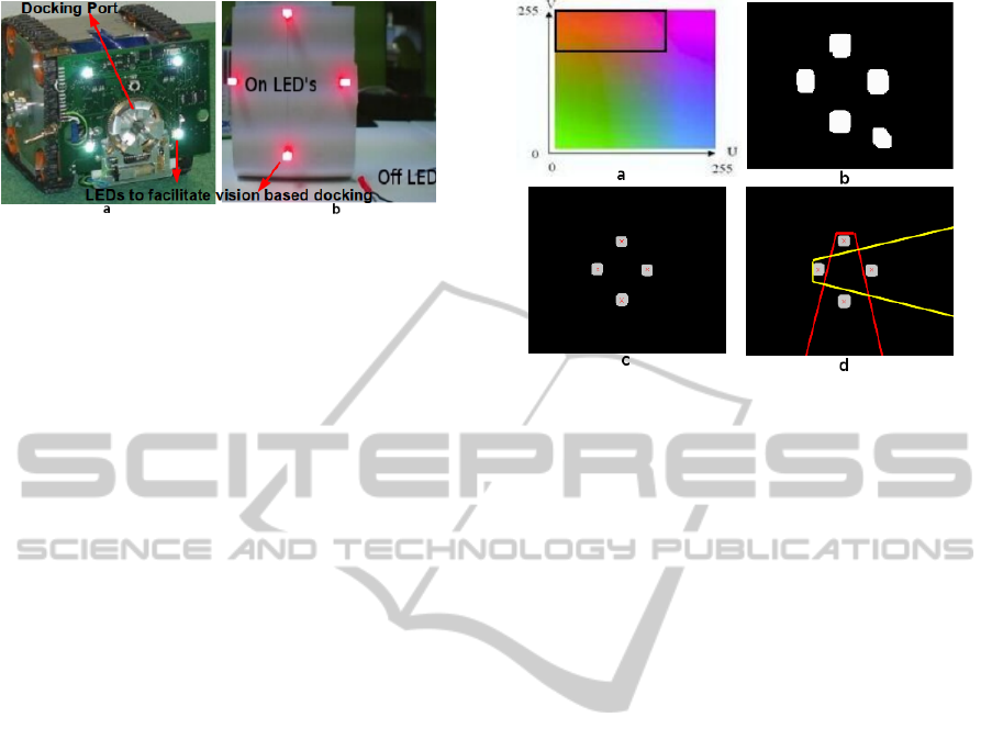
Figure 2: (a) Docking port and LEDs to facilitate vision
based docking. (b) Dummy docking port.
run in real time on small size robot. As this al-
gorithm will be running all the time (when docking
is required) in parallel with the other computation-
ally expensive algorithms (e.g. scene understanding)
and multi-robot communication algorithm, makes the
task more challenging. To address this problem, a
colour blob detection based approach to identify the
ON LED’s in the known pattern was developed. The
following observations complicates this task.
1. OFF LEDs will be detected as red blobs in the image.
However, in ON state, their centre appear red to human
eyes but white to vision sensor as shown in Figure 2b.
A red LED in OFF state is also shown for comparison.
2. As robots have only one camera and when close to the
port, LEDs go out of its vision, so alignment upto some
distance from port is possible. On getting very close,
support from other sensors (IR) would be required.
3. While approaching the blobs, the pattern can be very
titled depending on the direction and angle of approach.
Based on these observations an algorithm is re-
quired which also gives certain level of confidence to
drive the robot in the right direction to perform dock-
ing. The problem is therefore divided into a number
of processing steps which reduces the complexity in
every step while not sacrificing the performance. The
following processing steps are taken.
3.1 Blob Detection of LEDs in ON State
Implement a colour blob detection algorithm to de-
tect red blobs in the current image. This algorithm
directly processes the YUV images. In YUV format,
Y provides luminance, whereas U and V provide the
chrominance information (shown in Figure 3a). In
the current implementation, V values greater than 190
and U less than 200 are selected. In Figure 3a, the
range of UV values used to detect red blobs are identi-
fied by the black boundary. U values greater than 130
seems not required but its use makes the algorithm
less sensitive to change in the lighting condition.
To show the performance of algorithm to detect
red LEDs blobs, image shown in Figure 2b is pro-
Figure 3: (a) UV plane. (b) Output of blob detection algo-
rithm. (c) Blob statistical information. (d) Search field for
neighbouring blobs.
cessed. This image, captured by the robot vision sys-
tem, shows four red LEDs in ON and one in OFF
state. The output of blob detection algorithm (also
processed by the dilation algorithm to fill small holes
in the blobs) is shown in Figure 3b. The blobs caused
by both ON and OFF LEDs are detected. To deter-
mine the blobs from ON LEDs, the brightness infor-
mation from YUV image is utilized. By thresholding
the Y image and using it together with the output of
blob detection algorithm, the blobs caused by LEDs
in ON state are identified and are shown in Figure 3c.
3.2 Obtaining Statistics of LED Blobs
To obtain the statistical information of the LED blobs,
the image shown in Figure 3c is processed by the al-
gorithm. The image in Figure 3c is a binary image
in which 0 value is representing the dark part and 1
is representing the detected blobs. All the blobs are
appearing as a separate segments. The algorithm per-
forms segmentation (using Flood Fill approach) of the
image and assign a unique ID to each segmented re-
gion. This ID information helps determining the cen-
troid of each blob, hence provides the statistical in-
formation of the blobs. The centroid of the blobs are
marked with cross sign in Figure 3c.
3.3 Classification of Red LED Blobs
After determining the statistics, blobs satisfying the
required pattern are classified as Top, Bottom, Left
and Right LED blobs. The classification algorithm
makes a reasonable assumption that while scanning
the image from top to bottom, the first blob found is
most likely to be from the Top LED following some
SUPPORT FOR ROBOT DOCKING AND ENERGY FORAGING - A Computer Vision Approach
125
conditions. Otherwise, the rest of the blobs will be
checked one by one. These conditions are as follows.
• Around the currently assumed Top blob, a cone
shaped search field is defined as shown in red
colour in Figure 3d. In this field, the algorithm
try to locate the Bottom blob. Some checks are
made to avoid the blobs resulting from reflection
of Top LED to be considered as Bottom LED
blob. The bottom blob should not be detected
very close to the top blob. In the current imple-
mentation, it is defined to be detected at-least 20
pixels down from the top blob and the blob size
in pixels should be almost same as the top blob.
Here, 20 pixels limit was determined empirically
for QVGA resolution in which processing is done.
• Once the top and bottom blobs are found, then
their centre point is determined. Across this cen-
tre, 60 pixels wide search field is defined. The
blob which is found on the left side of this search
field is most likely the blob resulting from left
LED. Then again, a cone shaped search field is de-
fined, extending in right direction (shown in yel-
low colour in Figure 3d). Algorithm search this
field to look for the blob resulting from right LED.
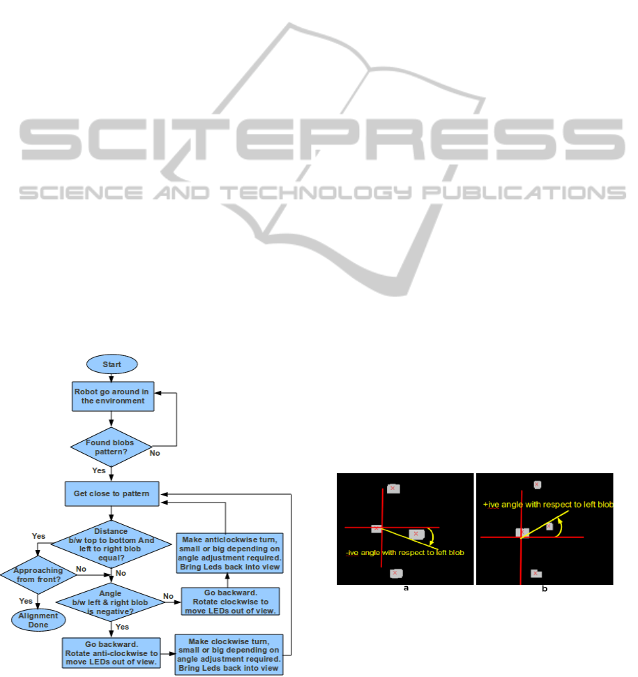
3.4 Control Algorithm
Flow diagram of control algorithm is shown in Fig-
ure 4. It performs following sequence of operation.
Figure 4: Flow diagram of control algorithm.
• Move robots in the environment and search for the
blobs in the required pattern. On finding the pat-
tern, the algorithm performs the blobs classifica-
tion. As there is a strong possibility that the robot
is not approaching the LEDs from the front but at
some angle and this angle could be small or large
(can not be identified clearly from distance), so
rather then performing alignment in the first go,
the robot first tries to get close to the blobs.
• If the distance between Top to Bottom and Left to
Right blobs are equal and robot was approaching
from front, then robot assumes that the maximum
precision is obtained using vision and control al-
gorithm stops there. Otherwise, the robot deter-
mine the direction of its approach.
• If the robot is approaching the LEDs from left
side with reference to the LEDs locations, then
the LEDs pattern will appear as shown in the fig-
ure 5a. The right LED blob will make a nega-
tive angle with the left blob. The control algo-
rithm will move the robot backward, rotate it anti-
clockwise so that the LED blobs go out of its vi-
sion. Then the algorithm will move the robot to
make a clockwise turn. How big is the turn? It
depends upon how big is the angle adjustment re-
quired. It will keep on making this turn until the
LEDs are back into its view field. Then it will
move the robot again towards the blobs to see the
further correction required.
• On the other hand, if the robot is approaching
from right side then the LEDs pattern will appear
as shown in the figure 5b. The right blob will
make a positive angle with the left blob. The con-
trol algorithm will move the robot backward, ro-
tate it clockwise and then makes an anti-clockwise
turn to bring the LEDs back into view. This pro-
cess continue until the robot align itself.
Figure 5: (a) Robot approaching from left side. (b) Robot
approaching from right side.
PECCS 2012 - International Conference on Pervasive and Embedded Computing and Communication Systems
126
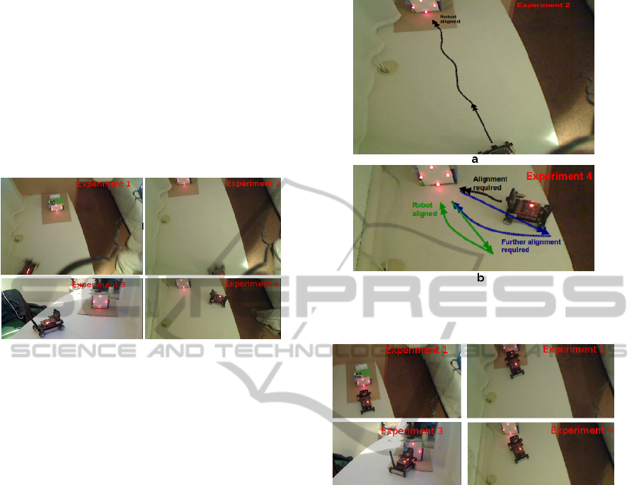
4 RESULTS
Using the approach presented in methodology sec-
tion, some experiments are performed to do robot
alignment with the docking port. Results from four
of these experiments are shown. In Figure 6 the start-
ing position of robots, before alignment, is shown. In
Experiment 1 and 2, the robot is less misaligned but in
experiment 3 and 4, robot requires more alignment as
it is approaching the LED’s with a very sharp angle.
Figure 6: Initial pose of the robots before alignment.
The trajectory of the robot in experiment 2, is
shown in Figure 7a. As the robot is less misaligned
with the LEDs, so control algorithm achieved the vi-
sion based alignment in less time. In comparison, the
result from experiment 4, which requires more align-
ment, is shown in Figure 7b. In Figure, the different
stages followed by the control algorithm to perform
alignment, are shown in terms of trajectories followed
by the robot in different colours. In the begining, the
robot approached the docking station straight (shown
in black) and determines the angle made by the left
blob with the right blob. As the angle is large, so it
moved back and make a big turn while approaching
the port to reduce the error in angle (shown in blue).
Finally, the robot was less misaligned so it moved
back again and makes a short turn (shown in green).
This time the robot was aligned and stops here.
The results obtained from the four experiments,
after alignment is done, are shown in Figure 8. In all
these experiments, the robots are almost fully aligned
with the four LEDs. This is the maximum support
which vision can provide in docking. If the robot tries
to get further close, then LED’s go out of its vision
and the robot can not take any further decision. For
final mechanical docking and precise alignment, the
control can rely on infra-red sensor information.
To demonstrate the functioning of vision based
docking support in a swarm robotic environment, an
experiment is performed in which a number of robots
are looking for docking port collectively. The dock-
ing port is installed on one of the robot. The robots are
Figure 7: (a)Robot trajectory in experiment 2. (b)Robot
trajectory in experiment 4.
Figure 8: Pose of the robot after performing alignment.
performing vision based obstacle avoidance, sharing
information with each other and simultaneously look-
ing for docking port. The robots are performing this
task collectively that is, when a robot in a swarm will
find the docking port, it will inform its team members
to stop looking for the docking port and quit the mis-
sion. After informing the team members, the robot
which finds the docking port, will align it self with
the docking port using vision so that docking opera-
tion can be facilitated. Several tests are performed us-
ing this approach. In Figure 9, one of the experiment
is shown. Three robots are used to perform the collec-
tive search operation. In the begining, the LEDs used
on the docking port of the robot are turned OFF as
shown in Figure 9a. The robots start the mission with
vision based obstacle avoidance, searching arena for
docking station and in parallel, also informing each
other whether any of them have found the docking
port. Finally, one robot finds the docking port, it in-
form the other team members that they are no longer
required to search for the docking station, and align it
self with docking station as shown in Figure 9b. All
SUPPORT FOR ROBOT DOCKING AND ENERGY FORAGING - A Computer Vision Approach
127

the other robots leave the search operation. It can be
noticed that, this vision based docking support may
be used for the docking of two robots, so that they
can become a single robotic organism. Or it can be
used for docking with the energy source so that bat-
tery recharging operation can be performed.
Figure 9: (a) A collective search for docking port (b) One
robot finds the docking port and the rest quit mission.
5 CONCLUSIONS
In this research, a simple but effective approach to
support the robot docking and battery recharging op-
eration using visual information is provided. Success-
ful experiments demonstrating the precise alignment
of the robot with the docking port are presented. This
approach enables the detection of the docking port
even when the robots are placed far from the dock-
ing station. Whereas approaches using other sensors
such as infrared, are able to perform docking only if
the robot is very close to the docking port. For the de-
tection of the docking port, as this approach is using
LEDs in a specific pattern which are very prominent
in the environment. So this enables the approach to
perform well even in the cluttered environment. From
the experimental results obtained from this research,
it is concluded that, the idea of using visual informa-
tion to perform docking, may be extended to use with
more complicated robotic systems which are design
to perform planetary exploration and which may re-
quire physical docking for sharing energy and com-
putational resources.
ACKNOWLEDGEMENTS
This research was funded by European Commission
Seventh Framework Programme FP7/2007-2013 re-
search project REPLICATOR.
REFERENCES
Bonani, M., Dorigo, M., Gross, R., and Mondada, F. (2005).
Autonomous self-assembly in mobile robotics. In
IRIDIA- Technical Report.
Dunbabin, M., Lang, B., and Wood, B. (2008). Vision-
based docking using an autonomous surface vehicle.
In International Conference on Robotics Automation
(ICRA).
Kernbach, S., Scholz, O., Harada, D., Popesku, S., Liedke,
J., Raja, H., Liu, W., Caparrelli, F., Jemai, J., Hav-
lik, J., Meister, E., and Levi, P. (2010). Multi-robot
organisms: State of the art.
Kurokawa, H., Murata, S., and Kakomura, K. (2006).
Docking experiments of a modular robot by visual
feedback. In International Conference on Intelligent
Robots and Systems.
Low, E. M., Manchester, I. R., and Savkin, A. V. (2007). A
biologically inspired method for vision-based dock-
ing of wheeled mobile robots. In Robotics and Au-
tonomous Systems, vol. 55, no. 10. page 769-784.
Nagarathinam, A., Levi, P., Kornienko, S., and Kornienko,
O. (2007). From real robot swarm to evolutionary
multi-robot organism. In IEEE Congress on Evolu-
tionary Computation.
REPLICATOR (2008). Replicator-robotic evolutionary
self-programming and self-assembling organisms. In
7th Framework Programme Project No FP7-ICT-
2007.2.1. European Communities.
Sastra, J., Park, M., Dugan, M., Taylor, C. J., Yim, M.,
and Shirmohammadi, B. (2007). Towards robotic self-
reassembly after explosion. In International Confer-
ence on Intelligent Robots and Systems.
Schmickl, T., Corradi, P., Kernbach, S., and Szymanski, M.
(2008). Symbiotic robot organisms: Replicator and
symbrion projects. In Special Session on EU-projects
. PerMIS 08, Gaithersburg, MD, USA.
Silverman, M., Nies, D., Jung, B., and Sukhatme, G.
(2002). Staying alive: A docking station for au-
tonomous robot recharging. In IEEE International
Conference on Robotics and Automation (ICRA).
SYMBRION (2008). Symbrion: Symbiotic evolutionary
robot organisms. In 7th Framework Programe Project
No FP7-ICT-2007.8.2. European Community.
Trianni, V., Christensen, A. L., Dorigo, M., Ampatzis,
C., and Tuci, E. (2009). Evolving self-assembly in
autonomous homogeneous robots: Experiments with
two physical robots. In Artificial Life.
Will, P. and Shen, W. M. (2001). Docking in self-
reconfigurable robots. In IEEE/RSJ International
Conference on Intelligent Robots and Systems.
Yamakita, M., Gross, R., and Dorigo, M. (2006). Self-
assembly of mobile robots from swarm-bot to super-
mechano colony. In Intelligent Autonomous System
(IAS) 9, Tokyo, Japan.
Zhang, D., Li, Z., Ling, M., and Chen, J. (2011). A mobile
self-reconfigurable microrobot with power and com-
munication relays. In International journal of Ad-
vanced Robotic Systems. ISSN 1729-8806. InTech.
PECCS 2012 - International Conference on Pervasive and Embedded Computing and Communication Systems
128
