
REAL-TIME 3D MULTIPLE HUMAN TRACKING WITH
ROBUSTNESS ENHANCEMENT THROUGH MACHINE LEARNING
Suraj Nair, Emmanuel Dean-Leon and Alois Knoll
Robotics and Embedded Systems, Technische Universit
¨
at M
¨
unchen, M
¨
unchen, Germany
Keywords:
Visual Tracking.
Abstract:
This paper presents a novel and robust vision-based real-time 3D multiple human tracking system. It is capable
of automatically detecting and tracking multiple humans in real-time even when they occlude each other.
Furthermore, it is robust towards drastically changing lighting conditions. The system consists of 2 parts, 1.
a vision based human tracking system using multiple visual cues with a robust occlusion handling module,
2. a machine learning based module for intelligent multi-modal fusion and self adapting the system towards
drastic light changes. The paper also proposes an approach to validate the system through zero-error ground
truth data obtained by virtual environments. The system is also validated in real-world scenarios.
1 INTRODUCTION
This paper presents a novel real-time 3D multiple hu-
man tracking system with the primary focus on ro-
bustness enhancement through machine learning. It
is a vision based system, capable of automatically de-
tecting human targets. After detecting the targets, the
trajectory of each detected target is tracked with a 3D
pose in real-time. The system has an ability to re-
solve target occlusions in real-time and maintain in-
dividual trajectories provided the targets do not leave
the designated tracking area. The occlusion handling
system resolves mutual occlusion between the targets
and serves as an important tool for robust tracking
under circumstances of mutual occlusion in multi-
ple camera views when the tracking scene consists of
many targets.
A machine learning based approach is introduced
to train and classify lighting conditions in the track-
ing environment. Lighting conditions being highly
influential in robust tracking, its classification helps
the tracker to take important decisions to maintain the
robustness. On the basis of this classification, intel-
ligent multi-modal fusion of two visual cues is per-
formed. Depending on the current situation, the op-
timal weights in which the visual cues are fused in
order to achieve the desired robustness is computed.
This approach improves the robustness of the tracking
system in terms of self adaptability to changing track-
ing conditions. Although the machine learning based
lighting conditions classification is useful in multi-
modal fusion, it finds an important use case in robust
pre-processing of camera images such as background
segmentation. Sudden changes in lighting conditions
can be detected and the background model can be up-
dated using this approach. The background model up-
date is not trivial in presence of foreground targets.
This paper introduces an approach to identify such sit-
uations and update the background model in presence
of foreground targets under drastic changes in lighting
conditions.
2 PRIOR ART
Several systems have been developed to track hu-
mans using multiple cameras in both un-calibrated
and stereo-calibrated fashion. (Santos and Morimoto,
2011) provides a systematic mention of approaches
(Eshel and Moses, 2008), (Fleuret et al., 2008), (Hu
et al., 2006), (Kim and Davis, 2006), which use un-
calibrated cameras and homography to perform peo-
ple tracking.
(Soto et al., 2009) present another multi-target
tracking system using multiple cameras. Their ap-
proach is focussed on a self-configuring camera net-
work consisting of cameras with pan-tilt. The cam-
eras keep track of the targets and adjust their parame-
ters with respect to each other.
(Khan and Shah, 2008) present a slightly different
approach of multi view tracking of people. They use
359
Nair S., Dean-Leon E. and Knoll A..
REAL-TIME 3D MULTIPLE HUMAN TRACKING WITH ROBUSTNESS ENHANCEMENT THROUGH MACHINE LEARNING.
DOI: 10.5220/0003824203590366
In Proceedings of the International Conference on Computer Vision Theory and Applications (VISAPP-2012), pages 359-366
ISBN: 978-989-8565-04-4
Copyright
c
2012 SCITEPRESS (Science and Technology Publications, Lda.)
information in combination from all views which is
projected back to each camera view and a planar ho-
mographic occupancy constraints for likelihood com-
putation.
(Francois et al., 2006) combines target occupancy
in the ground plane with colour and motion models
to track people in continuous video sequences. This
approach requires heuristics to rank the individual tar-
gets to avoid confusing them with another.
(Focken and Stiefelhagen, 2002) introduces a sys-
tem for tracking people in a smart room. They use a
calibrated camera system within a distributed frame-
work. Each camera runs on a dedicated PC. The de-
tected foreground regions are sent to a tracking agent
which computes the locations of people from the de-
tected regions. (Cai and Aggarwal, 1996) use grey
scale images from multiple fixed cameras to perform
the tracking. They use multivariate Gaussian mod-
els to estimate closest matches of humans between
consecutive image frames. The system proposed by
(Dockstader and Tekalp, 2001) is aimed at tracking
human motion with key focus on occlusions. Each
camera view is independently processed on a indi-
vidual computer. Within the Bayesian network, the
observations from the different cameras are fused to-
gether in order to resolve the independent relations
and confidence levels. An additional Kalman filter is
used to update the 3D state estimates.
(Chang and Gong, 2001) present a multi camera
people tracking system using Bayesian filtering based
modality fusion. (Zhao et al., 2005) presents another
stereo cameras based people tracking system. It is a
real-time system to track humans over a wide area.
A multi-camera fusion modules combines tracks of a
single target in all view to a global track.
Considering the state of the art, the primary contri-
bution of this work is made in the form of robustness
enhancement through machine learning which makes
the system robust to drastic changes in lighting condi-
tions and improves the tracker robustness through in-
telligent multi-modal fusion of two visual modalities.
Another important contribution is a robust occlusion
handling system which can resolve multiple occlusion
in real time. A novel benchmarking approach is pre-
sented due to un availibility of a unified approach for
existing systems unlike pedestrian detections systems.
3 SYSTEM ARCHITECTURE
The 3D multiple human tracking system uses visual
information from multiple cameras in order to auto-
matically detect and tracks humans in real time. The
detection process operates independent of the track-
ing allowing detection of new targets when they enter
the tracking area
1
while the tracker is tracking exist-
ing targets.
The target shape is modelled as a 3D rectangu-
lar box approximating to the dimensions of a human.
The appearance model is generated in the form of a
2D joint probability histogram in all camera views.
The target dynamics is modelled using the constant
white noise acceleration (CW NA) motion model. The
tracker uses a bank of SIR particle filters (Isard and
Blake, 1998), working on a 3D motion model, ap-
pearance model and optical flow. The particle filter
provides the sequential prediction and update of the
respective 3D states = (x,y,z). For real-time perfor-
mance, a global particle set is maintained and dis-
tributed evenly among the bank of particle filters in
order to maintain real-time performance.
3.1 Tracking Pipeline
Fig. 1 describes the complete pipeline of the track-
ing system. Each module is discussed in detail in the
subsections below.
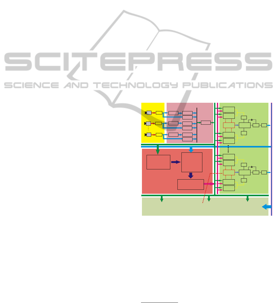
CAM0
Image Acquisition from
Calibrated USB Cameras
(25 ~35fps)
Grabber
RGB 444
Background
Segmentation
RGB to HSV
Conversion
PreProcessing ofCameraImages
Preprocessed
Image Stack
Automatic Online
Target Detection
(Detects new targets
and generate a model
foreach new target
Occlusion Test
(Checks if any target
occludes other targets in
each camera view)
Targets
-Count
-Ids
-Shape
-Appearance
-3D Pose
-Cam Occupancy
Particle Filter Bank
One filterforeach target
FromTarget ID 0 to ID NTarget
FeatureMatching
Color Histogram
Cam 0
Cam 0
Warp
Particle Filter
Target Id. 0
3D Pose(x,y ,z )
0 0 0
Cam N
Warp
Compute
Average
Output
Filter
TV-L1
Optical Flow
CAM2
Grabber
RGB 444
Background
Segmentation
RGB to HSV
Conversion
TV-L1
Optical Flow
CAMN
Grabber
RGB 444
Background
Segmentation
RGB to HSV
Conversion
TV-L1
Optical Flow
Intelligent
Data
Fusion
FeatureMatching
Color Histogram
Cam N
FeatureMatching
Optical Flow
Cam N
FeatureMatching
Optical Flow
Cam 0
Target Management
Machine Learning For
Robustness Enhancement
FeatureMatching
Color Histogram
Cam 0
Cam 0
Warp
Particle Filter
Target Id. N
3D Pose(x ,y ,z )
N N N
Cam N
Warp
Compute
Average
Output
Filter
Intelligent
Data
Fusion
FeatureMatching
Color Histogram
Cam N
FeatureMatching
Optical Flow
Cam N
FeatureMatching
Optical Flow
Cam 0
Figure 1: The figure illustrates the block diagram of the
multiple human tracking system.
3.1.1 Pre-processing of Sensor Images
Each sensor image undergoes a initial background
segmentation step followed by RGB to HSV colour
space conversion and optical flow segmentation.
1
The predefined camera workspace where the cameras
can view the targets.
VISAPP 2012 - International Conference on Computer Vision Theory and Applications
360

Figure 2: The figure illustrates the occlusion test system.
3.1.2 On Line Target Detection
This module automatically detects targets when they
enter the tracking area by performing a scan along the
tracking floor area using the 3D box target model. A
target is recorded if the target occupancy is beyond
a certain threshold in 2 or more cameras. The target
data consists of: 1. Unique Target ID, 2. Initial 3D
pose, 3. Shape data, 4. Appearance data, 5. Occlusion
test information, 6. Current 3D pose, 7. Velocity.
3.1.3 Occlusion Testing
It determines if a target is occluded by other targets
in a particular camera view. This information is es-
sential during target detection and tracking. These re-
gions are obtained by warping the 3D pose of each tar-
get under consideration on to each camera image (id=
0,....,M). Each target is defined by a 3-dimensional
container box comprised by 8 vertices
V
n
(t) =
v
j
∈ R
3
| j = 0,1,...,7
(1)
where, v
j
is the j
th
vertex of target shape model de-
fined in Cartesian space for the state s (t). These ver-
tices are projected on each camera as follows:
S
n
(t) =
r
j
∈ R
2
| r
j
= K [R | T ]v
j
,∀ v
j
∈ V
n
(t)
(2)
where, S
n
(t) is a set of the projected vertices of the
target n. K, R, and T describe the camera model.
Then, we define d
n
(t) as the Oriented Bounding Box
(OBB) of S
n
(t).
l
n
(t) =
(x,y) ∈ R
2
| (x,y) ∈ d
n
(t)
(3)
The geometric meaning of l
n
(t) is all the pixels within
the OBB d
n
(t). These pixels are used for the occlu-
sion test.
Fig. 2 illustrates the occlusion test system. This
system considers all the targets and computes their
occupancies in each camera image and computes the
euclidean distance from the camera to each target.
The bounding box of target farthest from the camera
is computed and rendered first. Once all targets are
rendered an overlap test is conducted between the
rendered regions to check which targets are occluded.
3.1.4 Tracker
Each target is equipped with its own particle filter.
The visual modalities used are 2D colour histograms
and optical flow. The tracking pipeline is as follows:
Tracker Prediction: The particle filter generates
several prior state hypotheses s
i
t
from the previous
distribution (s
i
,w
i
)
t−1
through a prediction model.
In this system the constant velocity model was used,
s
i
t
= s
i
t−1
+ ˙s
i
t−1
τ
i
+
1
2
v
i
t
τ
2
t
(4)
where, ˙s
i
t−1
is the velocity and is constant, v
i
t
is a ran-
dom acceleration. τ is the sampling interval.
Likelihood: The likelihood is computed on the pro-
jected hypothesis in each camera view. The colour
matching is computed through a distance measure of
the underlying and reference histograms through the
Bhattacharyya coefficient (Bhattacharyya, 1943).
B
m
(q
i
(s),q
∗
i
) =
"
1 −
∑
N
q
q
∗
i
(n)q
i
(s,n)
#
1
2
(5)
The colour likelihood is then evaluated under a Gaus-
sian model in the overall residual
P(z
col
|s
i
t
) ∝ exp(−
∑
M
log(B
2
i
/λ)) (6)
with given covariance λ. Similarly, the optical flow
distance measure if computed by comparing the pro-
jected motion vector of the hypothesis and the under-
lying motion vectors in the hypothesis region.
F
m
( f
i
(s), f
∗
i
) =
"
1 −
∑
N
q
f
∗
i
(n) f
i
(s,n)
#
1
2
(7)
F
m
is the resulting distance measure from the optical
flow modality for an individual hypothesis. The opti-
cal flow likelihood is computed as follows.
P(z
f low
|s
i
t
) ∝ exp(−
∑
M
log(F
2
i
/λ)) (8)
Multi-modal Fusion: The intelligent multi-modal
fusion module described in the next sections, gen-
erates the normalized weights W
col
and W
f low
. The
global likelihood for the hypothesis s
i
t
is then given
by
P(z
global
|s
i
t
) = P(z
col
|s
i
t
)W
col
+ P(z
f low
|s
i
t
)W
f low
(9)
Computing the Estimated State:
The average state
s
t
,
s
t
=
1
N
∑
i
w
i
t
s
i
t
, (10)
is computed and the three components (x, y, z) are re-
turned. In order to reduce the jitter in the output, the
average pose can be smoothed using an exponential
filter.
REAL-TIME 3D MULTIPLE HUMAN TRACKING WITH ROBUSTNESS ENHANCEMENT THROUGH MACHINE
LEARNING
361
4 MACHINE LEARNING TO
ENHANCE ROBUSTNESS
This section introduces an approach to improve the
robustness of the system using machine learning tech-
niques.
4.1 Learning Lighting Conditions
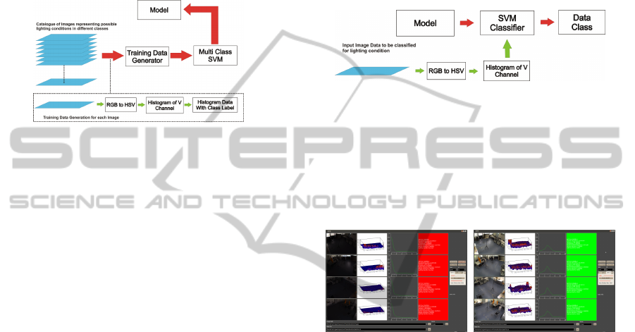
Figure 3: Building blocks of the SVM trainer for lighting
conditions.
Multi class support vector machines (Crammer
and Singer, 2001) can be used as an important tool
to learn the different possible lighting conditions that
could occur during tracking. They are divided into
classes where each class consists of a wide variety of
possible lighting conditions. From the learning pro-
cess, a model is generated which can be further used
for online classification of the lighting conditions.
Using this information the contribution of the indi-
vidual modalities towards multi-modal fusion module
can be computed.
Fig. 3 illustrates the building blocks of the sup-
port vector machine based training module for light-
ing conditions. It consists of a large set of training
samples in the form of images. Each training sam-
ple is processed to obtain the training data. Once the
training data is available, it is used by the svm train-
ing module to generate a model based on the classes
in which the training data were grouped. The light-
ing types are Insu f f icient lighting, Good lighting
and Saturated lighting representing classes Bad and
Good. The three stages in training are, see Fig. 4,
1. RGB to HSV Colour Space Conversion.
2. Histogram Computation: N bin normalized his-
togram of the V channel is computed representing
the intensity distribution.
3. Labelling: A class label is generated through au-
tomatic analysis or manual observation. The class
label together with the histogram data forms one
training data sample for the multi-class support
vector machine.
Around 4000 images of each class were used to
generate the training data. This makes the total train-
ing data set to consists of 12000 data samples. These
samples were generated using camera images ob-
tained from the real scene and from 3D simulations of
the entire scene, where the lighting conditions could
be controlled.
4.2 Classification of Lighting
Conditions
Figure 4: Building blocks of the SVM classifier for a light-
ing conditions.
Fig. 3 illustrates the building blocks of the sup-
port vector machine based lighting conditions clas-
sifier which uses the model generated by the SV M
trainer.
(a) (b)
Figure 5: On-line classification of the lighting condition.
Red: bad. Green: good.
Fig. 5 illustrates the test conducted for the on-
line classification of lighting conditions. The model is
able to classify and associate the current lighting con-
ditions in the camera views to their respective classes.
In this experiment, the SVM model was trained for
three classes of lighting conditions.
4.3 Background Model Update in the
Presence of Foreground Targets
Updating the background model when light changes.
The background model update is trivial in case of an
empty scene, but becomes a complex task in the pres-
ence of foreground targets in the scene being tracked.
This paper proposes an approach to update the
background model under changing lighting condition
while foreground targets are present in the scene. It
exploits the fact that during the course of tracking the
targets will move and expose the regions previously
VISAPP 2012 - International Conference on Computer Vision Theory and Applications
362
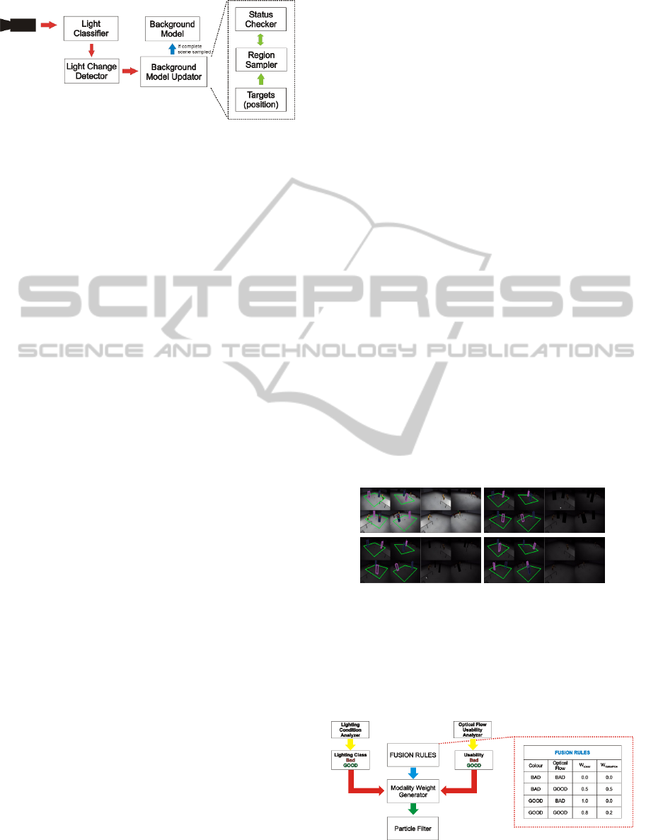
Figure 6: Background model update in presence of fore-
ground targets.
occluded by them. The occluded regions can be in-
cluded into the background model once they are vis-
ible due to target motion. The assumption that the
target will move is valid because, if the they do not
move, then the tracker only needs to perform a ex-
tremely small local search to keep track of the target
which does not require information from the back-
ground subtracter. Fig. 6 illustrate the Background
Model Update Procedure (BMUP) under changing
lighting conditions and in the presence of foreground
targets. The BMUP comprises of three main parts:
• Light Classifier: determines which class the
lighting conditions in the current camera image
belongs to.
• Light Change Detector: continuously reads
the classification result from the Light Classifier
and compares it with the classification results of
the previous instance and thereby detects drastic
changes in lighting conditions.
• Background Model Updater: updates the back-
ground model when it is notified about a light
change event by the Light Change Detector. It
uses the target positions, region sampler and the
status checker modules. If number of targets N =
0, the background model is updated with the im-
age I
id
. If N > 0, from each target position the
occupancy region L
id
of each camera (id=0,...,M)
is obtained. This is given by:
L (t) =
N
[
j=1
l
j
(t) (11)
where l
j
is given by Eq. 3.
This is the area that can not be included in the ref-
erence image for the new background model, and
needs to be included when exposed. The current
area for the reference image is initialised as:
D(t
0
) = (A ∩ L (t
0
))
c
(12)
Then the background image is initialized,
I
re f
=
{
I (x, y) | x,y ∈ D (t
0
)
}
(13)
where
A =
{
(x,y) | x = 1,2,...,width, y = 1,2,..., height
}
.
The unupdated regions are updated in time when
the targets are in motion, thereby exposing the
previously hidden regions, this is computed in the
next form:
h
L
(t) = (L (t − 1) \ (L (t) ∩ L (t − 1))) (14)
where h
L
is the new exposed pixels in the current
frame. Then the background image is updated us-
ing these pixels as follows:
I
re f
=
{
I (x, y) | x,y ∈ h
L
(t)
}
(15)
Finally, the current area at time t is updated as
below:
D(t) = D (t − 1) ∪ h
L
(t) (16)
D(t) is updated until
|
D(t)
|
=
|
A
|
.
When the background update process is initiated
the tracker suspends the new target detection process.
Further, instead of generating the HSV image from
the background segmented image, the tracker uses a
mask to highlight only the local regions surrounding
each target. Once the background model update is
complete, the tracker activates the background sub-
traction module in the target detection and initial pre-
processing phases. Figs. 7 illustrates the process. See
video: www.youtube.com/watch?v=LpnUkf2GEQ4
Figure 7: Background update in presence of foreground tar-
gets.
4.4 Modality Weight Generation for
Multi-modal Fusion
Figure 8: Intelligent fusion module to generate weights for
the individual modalities through scene analysis.
REAL-TIME 3D MULTIPLE HUMAN TRACKING WITH ROBUSTNESS ENHANCEMENT THROUGH MACHINE
LEARNING
363
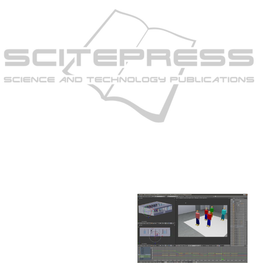
Fig. 8 describes the module performing the task
of generating the weights for the individual visual
modalities through scene analysis. This module con-
sists of two scene analysis units, each analysing the
usability of the individual modality in the current
scene. The usability of the modalities can be repre-
sented in the form of classes. The class categories
can be divided into two simple types namely, Bad and
Good or more if needed.
The optical flow usability class is considered to be
Bad when,
• The target is stationary or moving with a velocity
below a certain threshold V
st
• The target is moving closer than a defined thresh-
old d
min
to another target and the absolute differ-
ence of the optical flow direction components is
below a certain threshold θ
min
.
On the other hand, the optical flow usability class
is considered to be Good when,
• The target is moving with a velocity higher than
the defined threshold V
st
and at a distance greater
than d
min
with respect to all other targets.
• It has a velocity component higher than V
st
and
the absolute difference of its optical flow direction
component with other targets is greater than θ
min
.
Once the usability classes of the respective visual
modalities are known, this information is supplied to
the modality weight generator. The rule based fusion
technique is constructed through a fixed set of rules
defined by the user. These rules specify the combina-
tion of normalized weights to be assigned to the two
modalities for each possible combination of classes.
Fig. 8 illustrates a simple fusion rule data-bank for
the binary classes consisting of Bad and Good labels.
As mentioned above, these classes can be extended to
a wider range along with a more dense rule data-bank.
Once the individual weights for each modality is
obtained, they are fused in order to obtain a global
likelihood. The fusion operation is performed for
each hypothesis generated by the particle filter and
for each camera view. When both modalities are un-
suitable for tracking, the tracker declares a target loss
and instantiates the target recovery mechanisms in the
form of re-detection. The mathematical representa-
tion of the complete fusion procedure is formulated
below:
U
colour
i
= L
svm
I
id
, U
f low
i
= A
f low
T
tid
(17)
W
colour,
W
f low
= R
U
colour
i
,U
f low
i
tid
(18)
where, U
colour
i
is the usability class for the colour
modality in the i
th
hypothesis, L
svm
is the machine
learning based lighting condition classifier and I
id
is
the current image from the camera. U
f low
i
tid
is the us-
ability class for the optical flow modality in the i
th
hypothesis for the target with id tid. A
f low
is the func-
tion which performs the optical flow usability check
on the motion parameters of the current target given
by T
tid
. (W
colour
,W
f low
) are the unique weights for
the two modalities using the fusion rule data-bank R.
Finally, L
f ilter
h
is the global likelihood.
5 EXPERIMENTS
In this section the experiments are discussed.
5.1 Ground Truth Generation
There exists no unified benchmarking and quantita-
tive analysis framework for stereo multiple human
trackers. Different system test their method in dif-
ferent ways making quantitative comparisons diffi-
cult. Ground truth generation methods are either
manual, semi-automatic or automatic (Doll
´
ar et al.,
2009). They cannot guarantee accuracy since they
themselves have a certain tolerance. In order to gener-
ate ground truth without inherent errors, our test envi-
ronment was modelled in 3D in its completeness us-
ing Blender (Roosendaal and Selleri, 2004). The cam-
eras were reproduced with exact intrinsic and extrin-
sic parameters. The light sources were modelled sim-
ilar to the ones used in the lab environment. The hu-
mans were modelled using simple models. For each
target, the motion trajectories can be planned and sim-
ulated. The animation can be rendered using the per-
spective of the cameras. The simulated trajectory data
of each target was extracted through a python script
within Blender.
Figure 9: The lab environment modelled in 3D and extrac-
tion of simulated trajectory data.
VISAPP 2012 - International Conference on Computer Vision Theory and Applications
364
0 100 200 300 400 500 600
−6000
−4000
−2000
0
2000
4000
6000
Position Target 1 (X axis)
Frame Number [frame]
Target Position X [mm]
real postion
tracked position
0 100 200 300 400 500 600
−6000
−4000
−2000
0
2000
4000
6000
Position Target 1 (Y axis)
Frame Number [frame]
Target Position Y [mm]
real postion
tracked position
0 100 200 300 400 500 600
−2000
−1000
0
1000
2000
Error Position Target 1
Frame Number [frame]
Error [mm]
std x: 89.52 mm
std y: 98.34 mm
x error
y error
0 100 200 300 400 500 600
−6000
−4000
−2000
0
2000
4000
6000
Position Target 2 (X axis)
Frame Number [frame]
Target Position X [mm]
real postion
tracked position
0 100 200 300 400 500 600
−6000
−4000
−2000
0
2000
4000
6000
Position Target 2 (Y axis)
Frame Number [frame]
Target Position Y [mm]
real postion
tracked position
0 100 200 300 400 500 600
−2000
−1000
0
1000
2000
Error Position Target 2
Frame Number [frame]
Error [mm]
std x: 80.07 mm
std y: 81.21 mm
x error
y error
0 100 200 300 400 500 600
−6000
−4000
−2000
0
2000
4000
6000
Position Target 3 (X axis)
Frame Number [frame]
Target Position X [mm]
real postion
tracked position
0 100 200 300 400 500 600
−6000
−4000
−2000
0
2000
4000
6000
Position Target 3 (Y axis)
Frame Number [frame]
Target Position Y [mm]
real postion
tracked position
0 100 200 300 400 500 600
−2000
−1000
0
1000
2000
Error Position Target 3
Frame Number [frame]
Error [mm]
std x: 97.02 mm
std y: 99.81 mm
x error
y error
0 100 200 300 400 500 600
−6000
−4000
−2000
0
2000
4000
6000
Position Target 4 (X axis)
Frame Number [frame]
Target Position X [mm]
real postion
tracked position
0 100 200 300 400 500 600
−6000
−4000
−2000
0
2000
4000
6000
Position Target 4 (Y axis)
Frame Number [frame]
Target Position Y [mm]
real postion
tracked position
0
100 200 300 400 500 600
−2000
−1000
0
1000
2000
Error Position Target 4
Frame Number [frame]
Error [mm]
std x: 87.01 mm
std y: 71.95 mm
x error
y error
0 100 200 300 400 500 600
−6000
−4000
−2000
0
2000
4000
6000
Position Target 5 (X axis)
Frame Number [frame]
Target Position X [mm]
real postion
tracked position
0 100 200 300 400 500 600
−6000
−4000
−2000
0
2000
4000
6000
Position Target 5 (Y axis)
Frame Number [frame]
Target Position Y [mm]
real postion
tracked position
0 100 200 300 400 500 600
−2000
−1000
0
1000
2000
Error Position Target 5
Frame Number [frame]
Error [mm]
std x: 68.72 mm
std y: 85.37 mm
x error
y error
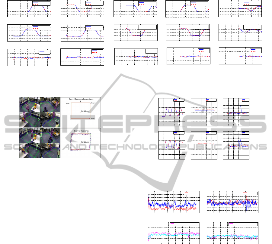
Figure 10: Illustration of the tracking system with 5 targets in the scene moving close to each other and two targets having
similar appearance.
Figure 11: Experiment results in real world environment
with 3 targets and the motion trajectories generated.
5.2 Experimental Validations
Fig. 10 illustrates the first test with 5 targets. It shows
the plots of the tracked trajectories along with the ac-
tual trajectories obtained from the ground truth gen-
erator. The third row represents the error computed
in the X and Y directions. The standard deviation of
the error is below 10 cm even under increased num-
bers of mutual occlusions simultaneously in multiple
cameras. See video: www.youtube.com/watch?v=-Y-
sZ2g53fM.
Fig. 11 illustrates a real experiment in the
lab. The red box representing the desired trajectory
and the actual tracked trajectories are shown. See
video:www.youtube.com/watch?v=wePVQ7cXB9c
Fig. 12 and video www.youtube.com/watch?v=u6
OFTVWO-qg presents an experiment with two tar-
gets having exactly similar appearance. There is a
sharp overshoot in the error in the dominant direction
of motion when the targets move in the same direc-
tion but recovers in a few frames through the occlu-
sion handling module. The average error is lower than
10 cm.
Fig. 13 validates the use of intelligent multi-
modal fusion in good and bad lighting.
The feature matching distance of colour histogram
worsens in the bad lighting condition while the opti-
0 200 400 600 800 1000
−6000
−4000
−2000
0
2000
4000
6000
Position Target 1 (Xax is)
Frame Number [frame]
Target Position X [mm]
real postion
tracked position
0 200 400 600 800 1000
−6000
−4000
−2000
0
2000
4000
6000
Position Target 1 (Yax is)
Frame Number [frame]
Target Position Y [mm]
real postion
tracked position
0 200 400 600 800 1000
−2000
−1500
−1000
−500
0
500
1000
1500
2000
Error Position Target 1
Frame Number [frame]
Error [mm]
std x: 216.46 mm
std y: 68.33 mm
x error
y error
0 200 400 600 800 1000
−6000
−4000
−2000
0
2000
4000
6000
Position Target 2 (Xax is)
Frame Number [frame]
Target Position X [mm]
real postion
tracked position
0 200 400 600 800 1000
−6000
−4000
−2000
0
2000
4000
6000
Position Target 2 (Yax is)
Frame Number [frame]
Target Position Y [mm]
real postion
tracked position
0 200 400 600 800 1000
−2000
−1500
−1000
−500
0
500
1000
1500
2000
Error Position Target 2
Frame Number [frame]
Error [mm]
std x: 270.44 mm
std y: 77.66 mm
x error
y error
Figure 12: Two targets with exactly similar appearance and
very close motion in the same direction.
0 100 200 300 400 500 600 700 800
0.2
0.25
0.3
0.35
0.4
0.45
0.5
Feature Matching Distance In Good Lighting
Frame Number [frame]
Distance
Colour Histograms
Optical Flow
0 100 200 300 400 500 600 700 800
0.1
0.15
0.2
0.25
0.3
0.35
0.4
0.45
0.5
Feature Matching Distance In Bad Lighting
Frame Number [frame]
Distance
Colour Histograms
Optical Flow
100 200 300 400 500 600 700
0.8
0.85
0.9
0.95
1
Likelihood In Good Lighting
Frame Number [frame]
Likelihood
Only Colour Histograms
Fusion of Colour Histogram and Optical Flow
100 200 300 400 500 600 700
0.8
0.85
0.9
0.95
1
Likelihood In Bad Lighting
Frame Number [frame]
Likelihood
Only Colour Histograms
Fusion of Colour Histogram and Optical Flow
Figure 13: Experiments results for multi-modal fusion.
cal flow distance remains fairly constant. The like-
lihood without fusion degrades in bad lighting con-
ditions while the likelihood with multi-modal fusion
remains fairly constant. This indicates that under bad
lighting conditions the multi-modal fusion of colour
and optical flow ensures robust and stable tracking re-
sults.
Fig. 14 illustrates the experiment conducted to
validate the performance under drastic changes in
lighting conditions in a real scenario. See video:
www.youtube.com/watch?v=yZHCXgdDf14
Fig. 15 shows the real application involving an
industrial robot. Human-robot-object interaction
was achieved under drastic changes in light. The
environment was dynamic as the robot was moving in
REAL-TIME 3D MULTIPLE HUMAN TRACKING WITH ROBUSTNESS ENHANCEMENT THROUGH MACHINE
LEARNING
365
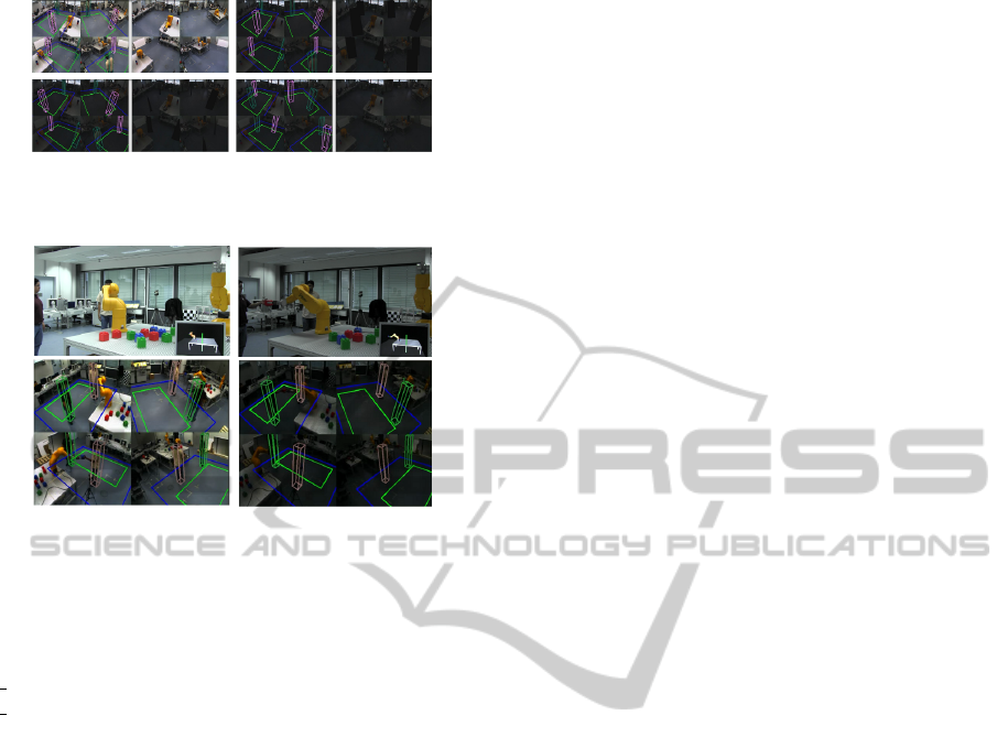
Figure 14: Experiment results in real world environment
under drastically changing lighting conditions.
Figure 15: Experiment with real robot.
the field of view of the cameras thereby influencing
the background subtraction and also occluding hu-
mans in different cameras while moving. See video:
www.youtube.com/watch?v=Pn7kyhlEkEc&list=UU
CgI4kT12FB7GjphbrIKAQ&index=2&feature=plpp
video
6 CONCLUSIONS AND FUTURE
WORK
To conclude this paper proposed and validated a ro-
bust multiple human tracker. The primary contri-
butions are: A vision based real-time 3D multiple
human tracking system; Simultaneous multiple oc-
clusion handling module; A machine learning based
model trained to classify quality lighting conditions;
Updating the background model in the presence of
foreground targets; Analysis of each visual modality
for intelligent fusion. Furthermore, a novel approach
through which zero error ground truth data for evalu-
ation and validation of the tracker was introduced and
experiments were conducted to very different aspects.
In the future work camera placements will be im-
proved for better stereo coverage. The target mod-
elled will be improved to resemble the human shape
more closely. The detection and occlusion handling
modules will be improved by adding a classification
engine such as in pedestrian detection systems to con-
firm the presence of a human. Addition visual modal-
ities will be introduced into the fusion engine.
REFERENCES
Bhattacharyya, A. (1943). On a measure of divergence
between two statistical populations defined by their
probability distributions. Bulletin of the Calcutta
Mathematical Society, 35:99–109.
Cai, Q. and Aggarwal, J. (1996). Tracking human mo-
tion using multiple cameras. In Pattern Recognition,
1996., Proceedings of the 13th International Confer-
ence on, volume 3, pages 68–72. IEEE.
Chang, T. and Gong, S. (2001). Tracking multiple people
with a multi-camera system. womot, page 0019.
Crammer, K. and Singer, Y. (2001). On the algorithmic
implementation of multi-class svms. In JMLR.
Dockstader, S. and Tekalp, A. (2001). Multiple camera
tracking of interacting and occluded human motion.
Proceedings of the IEEE, 89(10):1441–1455.
Doll
´
ar, P., Wojek, C., Schiele, B., and Perona, P. (2009).
Pedestrian detection: A benchmark. In CVPR.
Eshel, R. and Moses, Y. (2008). Homography based multi-
ple camera detection and tracking of people in a dense
crowd. In CVPR 2008. IEEE.
Fleuret, F., Berclaz, J., Lengagne, R., and Fua, P. (2008).
Multicamera people tracking with a probabilistic oc-
cupancy map. pattern analysis and machine intelli-
gence. IEEE Transactions on, 30(2):267–282.
Focken, D. and Stiefelhagen, R. (2002). Towards vision-
based 3-d people tracking in a smart room. In Multi-
modal Interfaces, 2002. IEEE Computer Society.
Francois, J. B., Berclaz, J., Fleuret, F., and Fua, P. (2006).
Robust people tracking with global trajectory opti-
mization. In In Conference on Computer Vision and
Pattern Recognition, pages 744–750.
Hu, W., Hu, M., Zhou, X., Tan, T., Lou, J., and Maybank, S.
(2006). Principal axis-based correspondence between
multiple cameras for people tracking. pattern analy-
sis and machine intelligence. IEEE Transactions on,
28(4):663–671.
Isard, M. and Blake, A. (1998). Condensation – conditional
density propagation for visual tracking. International
Journal of Computer Vision (IJCV), 29(1):5–28.
Khan, S. and Shah, M. (2008). Tracking multiple occluding
people by localizing on multiple scene planes. IEEE
transactions on pattern analysis and machine intelli-
gence, pages 505–519.
Kim, K. and Davis, L. (2006). Multi-camera tracking and
segmentation of occluded people on ground plane us-
ing search-guided particle filtering. Computer Vision–
ECCV 2006, pages 98–109.
Roosendaal, T. and Selleri, S. (2004). The Official Blender
2.3 Guide: Free 3D Creation Suite for Modeling, An-
imation, and Rendering. No Starch Press.
Santos, T. T. and Morimoto, C. H. (2011). Multiple camera
people detection and tracking using support integra-
tion. Pattern Recognition Letters, 32(1):47–55.
Soto, C., Song, B., and Roy-Chowdhury, A. (2009). Dis-
tributed multi-target tracking in a self-configuring
camera network. In CVPR 2009. IEEE.
Zhao, T., Aggarwal, M., Kumar, R., and Sawhney, H.
(2005). Real-time wide area multi-camera stereo
tracking. In Computer Vision and Pattern Recogni-
tion, 2005. CVPR 2005. IEEE Computer Society.
VISAPP 2012 - International Conference on Computer Vision Theory and Applications
366
