
HYBRID 4-DIMENSIONAL AUGMENTED REALITY
A High-precision Approach to Mobile Augmented Reality
Paul Miranda
1
, Nikita Sharakhov
1
, Jules White
1
, Mani Golparvar-Fard
2
and Brian Dougherty
1
1
Dept. of Electrical and Computer Engineering, Virginia Tech, Blacksburg, VA, U.S.A.
2
Dept. of Civil and Environmental Engineering, Virginia Tech, Blacksburg, VA, U.S.A.
Keywords: Augmented Reality, Mobile Computing, Computer Vision, Structure from Motion.
Abstract: A construction project requires a large amount of cyber-information, such as 3D models. Unfortunately, this
information is typically difficult for construction field personnel to access and use on-site, due to the highly
mobile nature of the job, as well as a hazardous work environment. Field personnel rely on carrying around
large stacks of construction drawings, diagrams, and specifications, or traveling to a trailer to look up
information electronically. This paper presents HD
4
AR, a mobile augmented reality system for construction
projects that provides high-precision visualization of semantically-rich 3D cyber-information over real-
world imagery. The paper examines the challenges related to augmenting reality on a construction site,
describes how HD
4
AR overcomes these challenges, and empirically evaluates the capabilities of HD
4
AR.
1 INTRODUCTION
Emerging Trends & Challenges: In 2010, the US
spent 816 billion dollars on construction projects
(AGC, 2011). It is estimated that a 0.1%
improvement in efficiency of project delivery could
save roughly $200 million. Even though there are
significant potential cost savings, the construction
industry still faces major challenges in tracking and
monitoring operations to promptly identify, process,
and communicate discrepancies between actual and
expected performances. The National Academy of
Engineering has identified “enhanced visualizations,
through advances in virtual and augmented reality”
as a key challenge for 21
st
century engineering
(NAE, 2011).
To successfully control execution of a project,
the actual (physical) status of the infrastructure
under construction needs to be constantly monitored
and compared with the project’s cyber-information
model, known as a Building Information Model
(BIM) (Eastman et al., 2008). The BIM is a 3D CAD
model that is annotated with cyber-information that
provides semantics for the CAD elements, such as
structural geometries and, their spatial and material
properties, and can be augmented with cost and
schedule information.
Despite the importance of cyber-physical
information association on a construction site,
current monitoring practices include manual and
time-consuming data collection (e.g., walking
around a construction site and writing down
information on paper), non-systematic analysis (e.g.,
rough comparisons of the notes to the 2D
construction plans), and visually/spatially complex
reporting (Golparvar-Fard et al., 2009); (Navon and
Sacks, 2007) (e.g., estimating how real-world 3D
physical structures correspond to 2D building plans
or virtual 3D models).
Open Problem: A key issue with these manual
processes is that practitioners cannot access and
interact with cyber-information through the physical
structures that they are building. For example, there
is no way for a field engineer to see a 3D plan for a
wall overlaid directly on top of the physical element.
Instead, field engineers must either carry bulky
stacks of drawing and documents, or make trips back
and forth to construction trailers and offices to look
up plans for building elements and compare them to
what was seen on the construction site. Because
there is no easy way to visualize and query the BIM
through the actual physical construction elements, it
is difficult for field personnel to quickly detect
discrepancies between the physical construction
elements and the cyber building plans. Without
quick identification of discrepancies, managers
cannot easily adjust the construction plan to
minimize the impact of problems.
156
Miranda P., Sharakhov N., White J., Golparvar-Fard M. and Dougherty B..
HYBRID 4-DIMENSIONAL AUGMENTED REALITY - A High-precision Approach to Mobile Augmented Reality.
DOI: 10.5220/0003824401560161
In Proceedings of the 2nd International Conference on Pervasive Embedded Computing and Communication Systems (PECCS-2012), pages 156-161
ISBN: 978-989-8565-00-6
Copyright
c
2012 SCITEPRESS (Science and Technology Publications, Lda.)

While smartphones provide the platform and tools
for AR (Wagner, 2009), existing mobile AR
approaches are not well suited for a construction
environments due to their lack of accuracy in
spatially locating the user and rendering cyber-
information over the correct physical elements. On a
construction site, discrepancies between physical
elements and the BIM must be detected to within a
few centimetres or less. AR approaches, based on
GPS and compass sensors (Gotow et al., 2010), can
have multiple meters of inaccuracy, making them
unreliable for construction scenarios.
Solution Approach Hybrid 4-Dimensional
Augmented Reality: This paper presents an
augmented reality approach, called Hybrid 4-
Dimensional Augmented Reality (HD
4
AR) that
allows construction field personnel to use mobile
devices, such as a smart phone or tablet, to take
pictures that include a specific construction element,
see BIM elements visually overlaid on top of the
real-world imagery, touch or click on a BIM element
in the image, and be presented with a detailed list of
cyber-information, such as plan information (e.g.,
budget, specifications, architectural/structural
details) or actual information (e.g., cost, safety
provisions, physical progress) related to the physical
element. Screenshots from the Android HD
4
AR
client are shown in Figure 1.
This paper provides the following contributions to
the study of high-precision augmented reality
systems:
1. The paper shows how computer vision
algorithms can eliminate the need for external
sensors to provide reliable location tracking
information for providing context awareness.
2. The paper demonstrates how imagery of physical
elements can be used to access cyber-information.
3. The paper describes an AR technique with high-
precision that does not rely upon marking physical
construction elements with fiducial tags or external
equipment to provide high-precision localization.
The remainder of this paper is organized as follows:
Section 2 presents a motivating example that we use
to illustrate the challenges of associating cyber-
physical information on a construction site; Section
3 discusses HD
4
AR and its approach to high-
precision cyber-physical information association;
and Section 4 presents concluding remarks.
2 MOTIVATING EXAMPLE
As a motivating example, we use a scenario where a
field engineer is concerned about the construction
progress and quality of a concrete foundation wall.
With current approaches, the field engineer would
return to a construction trailer or office and open 2D
construction drawings (at best a 3D BIM), project
specifications, and the schedule to find out when the
construction of this element is expected to be
finished and what is the required quality of the
outcome. Once the drawings and/or 3D building
model is opened, the field engineer must navigate
the model to determine which, of possibly hundreds
or thousands of walls, is the foundation wall of
concern. Moreover, once the information is
obtained, the field engineer may need to return to the
construction site to compare the information that
was retrieved to the actual construction status of the
real foundation wall. Because there is no way to
directly query the cyber information for the wall, the
field engineer may not notice a discrepancy and will
not be able to decide on a corrective action to
minimize the impact of the discrepancy.
Instead, it would be beneficial if the field
engineer can use the foundation wall as the basis for
the query. A picture provides all that is needed to
localize the user with respect to their environment,
and thus reduce the information available down to
what is relevant to the current scene. Given the close
proximity of construction elements, the location and
orientation of the picture needs to be accurately
estimated to return the related information to the
field engineer. This process should not affect the
construction’s workflow by requiring tagging of
elements, which considering the number of elements
on a typical residential building construction site
(~1000-30,000 elements), makes tagging time
consuming and often impractical.
3 HYBRID 4-DIMENSIONAL
AUGMENTED REALITY
Using computer vision, researchers have shown that
a set of overlapping images can be used to extract
the 3D geometry of a stationary object, such as a
building under construction (Golparvar-Fard et al.,
2011); (Cheng and Chen, 2002); (Golparvar-Fard et
al., 2009). As shown in Figure 1 the 3D geometry
extracted using computer vision can then be overlaid
and aligned with manually created BIM models of
the construction project to create a fused cyber-
physical model. Numerous research approaches have
looked at the applications of these techniques
(Golparvar-Fard et al., 2011); (Kiziltas et al., 2008).
HYBRID 4-DIMENSIONAL AUGMENTED REALITY - A High-precision Approach to Mobile Augmented Reality
157

After the cyber (e.g., BIM elements) and physical
(e.g., extracted 3D geometry) models are aligned,
they can be compared to determine how the actual
state of the physical object compares to the
representative cyber-model. Researchers have shown
that the fused cyber-physical model is accurate to
within millimeters (Golparvar-Fard et al., 2011) and
can be used to predict with high accuracy the actual
construction progress versus the planned cyber-
model, even when visual obstructions are present
(Golparvar-Fard et al., 2010). Moreover, as shown in
Figure 1, the fused cyber-physical model can be
used to precisely predict where cyber-information,
such as BIM elements, should appear in the
original photographs and where physical objects
actually appear in the cyber 3D space. This ability
to track where BIM elements (i.e., cyber-identities)
should appear in photographs serves as the
foundation of HD
4
AR.
3.1 HD4AR Usage Overview
HD
4
AR extends and integrates our previous research
efforts in GPS-based AR, mobile device software
optimization, and fused cyber-physical model
construction to create a novel hybrid approach that is
focused on fusing new photographs with existing
cyber-physical models. HD
4
AR provides
augmented photographs, rather than real-time
augmented camera imagery. As shown in Figure 1,
using our approach, a field engineer is able to take a
photo of a physical object and the mobile device
works with a backend server to produce an updated
photo augmented with the cyber-information
associated with the physical objects in view. The
entire end-to-end process after the photograph is
taken requires roughly a minute. The augmented
photographs, with cyber-physical information
associations, are accurate to within a few
millimeters (e.g., 1-5mm) due to the empirically
demonstrated high precision that computer vision
algorithms provide (Golparvar-Fard et al., 2011).
Moreover, after a field engineer has taken a
photograph, he or she is able to select physical
objects in view as the context and the system uses
the fused cyber-physical model to identify the cyber-
identity of those objects.
3.2 HD
4
AR Bootstrapping Process
In order to augment a given photograph with cyber-
information, the HD
4
AR system requires that
construction workers field personnel first take
overlapping photos of the construction site. These
photos are used to extract an initial 3D point cloud
of the site in a process known as Structure from
Motion (SfM). SfM produces a point cloud of the
natural visual features of the image set, estimating
the 3D position of the features through image feature
matching and an optimization process called bundle
adjustment. This 3D point cloud is then aligned with
the BIM in order to provide a correspondence
between physical world positions and positions in
the BIM.
The HD
4
AR system uses the Bundler package
implementation of Structure From Motion (Snavely
et al., 2006) to create the point cloud by the
following process:
1. Extract Visual Features: A feature-detection
algorithm is run on each image to create a key file of
feature descriptors to be used as the basis for
matching images to one another. Bundler by default
uses the SIFT (Scale Invariant Feature Transform)
algorithm (Lowe, 2004).
2. Match Visual Features: The set of visual
features for each image are iteratively compared
against each other, developing matching “tracks”.
These tracks consist of specific feature points of
multiple images, which are believed to represent the
same physical feature point.
3. Estimation of Camera Parameters: Beginning
with the two images containing the largest number
of matches (or by manually selecting two initial
images for bundling), the camera parameters are
estimated for each image, and the 3D positions of
their feature points are estimated. Then, each
additional image attempts to register with the 3D
cloud, using EXIF data to initialize focal length, and
adding in the tracks of matched points within their
view to expand the point cloud, and provide further
basis for other images. This registration fails in the
event that the estimated 3D layout of its matched
points does not mesh with the set positions of the
previous images.
4. Bundle Adjustment: In addition, while the
images are being bundled, the bundle is run through
a sparse bundle adjustment to minimize the error in
the predicted 2D positions of the feature points in
the photographs given their assigned 3D positions
and where the feature points actually appear in the
image.
3.3 Photograph Augmentation Process
Figure 1 shows screenshots from the HD
4
AR client
running on an Android device with Android version
2.3.4. Once the point cloud is generated, the system
is prepared to augment photos sent from the HD
4
AR
PECCS 2012 - International Conference on Pervasive and Embedded Computing and Communication Systems
158
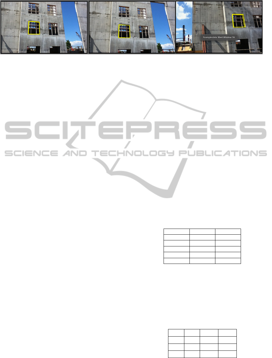
Figure 1: Screenshots of the android HD
4
AR client overlaying bim information related to a window.
client running on a user’s mobile device. From a
high-level perspective, this process operates as
follows: Step 1, the field engineer, upon finding a
section of the worksite he/she wishes to query, takes
a picture of the area using a mobile device. Step 2,
the device uploads the captured image to the HD
4
AR
server. Step 3, the server runs a reduced form of the
structure from motion algorithm to localize the
image with the base point cloud. Step 4, using the
localized image as input, the server determines what
BIM objects are within the image’s field of view,
and where they appear. Step 5, the objects are sent
back to the user device with positional information.
Step 6, the user device renders the captured image,
overlaid with the returned objects.
Step 1. Localization of Physical Elements in
Cyber Model. As shown in Figure 1, a physical
construction object (1) can be located in the 3D
geometry model (2) (actual physical model),
extracted with computer vision algorithms, and then
mapped to 3D BIM elements in the (3) cyber model
(e.g., BIM). This determination of the cyber-identity
relies on mapping between the coordinate spaces of
the models. If a physical object is at the same
coordinates in the extracted 3D point cloud as a
specific cyber-identity in the BIM, then it is
associated with that cyber-identity. The (4) cyber-
identifier, in turn, is associated with a BIM element
and cyber-information items that contain data about
the concrete foundation wall corner, such as
concrete specs or expected quality of the finished
surface, are associated with the cyber-identity.
Step 2. Reduced Single-image SfM. The user’s
photograph must be localized with respect to the 3D
point cloud, using a reduced sequence of SfM
algorithm steps used to create the point cloud itself.
An initial estimate of the focal length of the camera
used to take the image is extracted from the image's
EXIF tags, or cross-referenced from a list of camera
types. Next, feature point extraction is done to create
a key file for the image that lists all of the image’s
feature points. The key file and the focal length are
then used to mesh the image into the point cloud.
The image’s feature points are matched against the
feature points of other images in the set. If matching
succeeds, the pose of the camera that took the image
is known, resulting in rotation and translation values
for the camera that took the newly added image, and
adjustment performed on the new point cloud bundle
to refine its accuracy.
Step 3. Building the Transformation Matrix.
When an image is added to an existing point cloud
bundle, the bundle adjustment will optimize with
respect to the relative locations of all images in the
bundle, including the newly added image, resulting
in a new coordinate system. To determine visible
cyber-elements, the 3D positions must be
transformed into this new coordinate space. This is
done using a transformation matrix built using four
tracked points from both the original and
transformed bundles, used to solve Ax=B, where
Matrix is a 12x12 matrix formed from using the
positions of four points:
Table 1: Matrix A, formed with the original point
coordinates.
Point1 Z Z
Z Point1 Z
Z Z Point1
Point2 Z Z
… … …
Z Z Point4
where =
[
,
,
,1
]
, = [0,0,0,0]
is a 1x12 matrix composed of the x, y, and z
positions of the translated points from the new
bundle.Solving for produces a 1x12 matrix, which
produces the transformation matrix T when parsed
as:
Table 2: The Transformation Matrix.
X[0] X[1] X[2] X[3]
X[4] X[5] X[6] X[7]
X[8] X[9] X[10] X[11]
0 0 0 1
Step 4. Transformation of the BIM Overlay
Positions to New Coordinate Space. The 3D
HYBRID 4-DIMENSIONAL AUGMENTED REALITY - A High-precision Approach to Mobile Augmented Reality
159

coordinate of each BIM overlay position is matrix-
multiplied to produce the BIM overlay’s relative
position in the new coordinate system, i.e.:
=∗
1
(1)
Step 5. Mobile Augmented Photo Viewer and
Touchscreen Interface. Having determined the
localized position of the camera in 3D space and
transformed all relevant BIM overlay points into the
new coordinate space, the next step is to determine
which of the BIM’s cyber-information items are
visible in the user’s image by projecting their 3D
coordinates into the 2D space of the image. This 3D
to 2D project is done by following this sequence of
steps:
1. Item position in camera coordinates, where R is
the rotation matrix of the camera, t is the translation
matrix, and X is the 3D coordinate of the point.
= ∗ +
(2)
2. Flatten to Z-axis.
= − / .z
(3)
3. Resolve to 2D position, where is the estimated
focal length, p’ is the point in pixel coordinates:
′ =
∗ r() ∗
(4)
r()=1.0+1∗||||^2+2∗||||^4
(5)
where
1,2 are the estimated distortion parameters.
Equations (2), (3), (4), and (5) used from Bundler's
User Manual.
Cyber-information items with 2D positions
within the bounds of the photograph are sent back to
the mobile device along both their calculated 2D
locations in the photograph and any textual data
associated with the item.
Figure 1 shows screenshots from the Android
HD
4
AR client overlaying BIM information related
to a window on a photograph. In the screenshots, the
3D BIM information is precisely aligned with the
real-world imagery despite changes in the position
and orientation of the user’s device. As shown in the
third screenshot, clicking on elements can show
additional cyber-information, such as this Android
Toast notification, or open more detailed list views.
4 CONCLUDING REMARKS
The construction industry stands to gain much
through the integration of cyber-information into
regular operation. The HD
4
AR system was designed
with the intent of bringing augmented reality to
construction technology, to better facilitate the use
of cyber-information around worksites. It takes vital
project information, (such as object placement,
building materials, project scheduling, work
delegation, etc.) which traditionally has been
difficult to access on a jobsite (yet remains very
important to project specification and completion),
and makes it mobile, accessible, and possible to
visualize over real-world imagery.
From our work developing mobile AR for
construction sites, we learned the following
important lessons:
1. Localization of Users Can be Accomplished
Using Only 2D Images as Input. HD
4
AR
demonstrates that it is possible to develop
augmented reality systems without the need for
external modifications; signal tracking; or
GPS/wireless tracking modules, avoiding the pitfalls
inherent to such techniques on construction sites.
Using only captured images, SfM techniques can be
used to build a base geometric model, which then
can be used as a point of reference for other pictures
to estimate relative location.
2. Information Retrieval Using HD
4
AR Can be
Done in Less Time than Traditional Means. With
current manual construction processes, construction
field personnel must walk from an area of the
construction site to the construction trailer, lookup
up BIM information in a laptop computer, and
estimate its correspondence to the real-world state of
the construction site. While there has not been
research done specifically into how long it takes an
on-site engineer to retrieve information, it can be
mathematically shown that (in most cases), HD
4
AR
takes less time than manually retrieving the data.
Our results showed that HD
4
AR takes around 100
seconds to process and localize an image using the
largest base of images. Considering average human
walking speed to be around 1 m/s, this means the
average human will cover around 100m in 100s. So,
in the event that the command trailer lies farther than
100m away, the engineer has already spent more
time walking to the trailer than it takes for
augmentation. Moreover, this estimate does not even
consider the time it takes to manually narrow down
the results and find the relevant information on a
laptop, which, depending on how complex a project
is, could take considerable time.
3. More Can be Done to Improve the Robustness
of the Localization Algorithm. While our results
do show that the HD
4
AR system can be used for
localization, proving the concept of using natural
PECCS 2012 - International Conference on Pervasive and Embedded Computing and Communication Systems
160

features as a basis for augmentation, only 20-25% of
pictures, on average, can be localized. Improving the
likelihood of an image being matched to its
surroundings will increase system usability and
performance.
4. There is a Need to Develop a Simple Means of
Automatically Aligning the Geometric and
Cyber-Models to Facilitate Augmentation. A key
aspect of the HD
4
AR system is being able to
augment an image with associated cyber information
housed in a cyber-physical model. In order for this
to work, the geometric and cyber-models must be
aligned so that a user localized to the geometric
model will simultaneously be localized with respect
to the cyber model. Our current approach requires
manual alignment of these models, which is not
difficult, but not automated.
Our current version of HD
4
AR provides construction
AR with millimetre precision and augmentation of
photographs in ~1 minute. In future work, we are
planning to field test HD
4
AR on several construction
sites and improve both its speed and robustness.
REFERENCES
NAE (National Academy of Engineers of the National
Academies Grand Challenges of Engineering), “Grand
challenges for engineering”, 2011.
C. M. Eastman, C. Eastman, P. Teicholz, and R. Sacks,
BIM Handbook: A guide to building information
modeling for owners, managers, designers, engineers,
and contractors, John Wiley & Sons Inc, 2008.
M. Golparvar-Fard, F. Peña-Mora, and S. Savarese,
“D4AR-A 4-dimensional augmented reality model for
automating construction progress data collection,
processing and communication,” Journal of
Information Technology in Construction (ITcon),
Special Issue Next Generation Construction IT:
Technology Foresight, Future Studies, Roadmapping,
and Scenario Planning, vol. 14, 2009, p. 129–153.
R. Navon and R. Sacks, “Assessing research issues in
automated project performance control (APPC),”
Automation in construction, vol. 16, 2007, p. 474–484.
M. Golparvar-Fard, F. Pena-Mora, and S. Savarese,
“Integrated sequential as-built and as-planned
representation with D4AR – 4 dimensional augmented
reality - tools in support of decision-making tasks in
the AEC/FM industry,” ASCE Journal of Construction
Engineering and Management, 2011.
M. Golparvar-Fard, S. Savarese, and F. Pena-Mora,
“Automated Model-based Recognition of Progress
Using Daily Construction Photographs and IFC-Based
4D Models,” 2010.
J. B. Gotow, K. Zienkiewicz, J. White, and D. C. Schmidt,
“Addressing Challenges with Augmented Reality
Applications on Smartphones,” Mobile Wireless
Middleware, Operating Systems, and Applications,
2010, p. 129–143.
Wagner; D. Schmalstieg, "History and Future of Tracking
for Mobile Phone Augmented Reality," Ubiquitous
Virtual Reality, 2009. ISUVR '09. International
Symposium on, pp.7-10, 8-11 July 2009
M. Y. Cheng and J. C. Chen, “Integrating barcode and
GIS for monitoring construction progress,”
Automation in Construction, vol. 11, 2002, p. 23–33.
S. Kiziltas, others, Technological assessment and process
implications of field data capture technologies for
construction and facility/infrastructure management,
ITcon, 2008.
M. Golparvar-Fard, F. Peña-Mora, C. A. Arboleda, and
S.H. Lee, “Visualization of construction progress
monitoring with 4D simulation model overlaid on
time-lapsed photographs,” Journal of Computing in
Civil Engineering, vol. 23, 2009, p. 391.
AGC (Associated General Contractors of America), “The
economic impact of construction in the United States”,
2011, http://www.agc.org/galleries/econ/ National%
20Fact%20Sheet.pdf
N. Snavely, S. M. Seitz, and R. Szeliski. “Photo tourism:
exploring photo collections in 3D”. In ACM
SIGGRAPH 2006 Papers (SIGGRAPH '06). ACM,
New York, NY, USA, 835-846, 2006.
D. G. Lowe. "Distinctive Image Features from Scale-
Invariant Keypoints" University of British Columbia
Vancouver, B.C., Canada. 2004
HYBRID 4-DIMENSIONAL AUGMENTED REALITY - A High-precision Approach to Mobile Augmented Reality
161
