
DEBLOCKING FOR DYNAMIC TRIANGLE MESHES
Jan Rus and Libor V´aˇsa
Department of Computer Science and Engineering, Faculty of Applied Sciences
University of West Bohemia, Univerzitn´ı 8, Plzeˇn, Czech Republic
Keywords:
Static Triangle Meshes, Dynamic Triangle Meshes, Data Compression, Coddyac, Clustering, Blocking
Artifacts, Deblocking, Visual Quality.
Abstract:
Mesh segmentation (clustering) is a useful tool, which improves compression performance. On the other hand,
per-partes processing of meshes often leads to new types of artifacts - cracks and shifts on the borders between
clusters. These artifacts are detected by both, Human Visual System (HVS) and perceptually-motivated dis-
tortion metrics. In this paper, we present a post processing algorithm, which aims at reducing such artifacts
without needing any additional data - using only information about the cluster distribution that is already
present at the decoder. A rigid transformation, which minimises the border artifacts, is iteratively computed
and applied per cluster. Our experiments show that this approach leads to a reduction of distortion, as mea-
sured by the STED metric, by up to 18% for low bitrates. We also present visual results confirming that the
improvement is well visible.
1 INTRODUCTION
The use of 3D data in the form of triangle meshes
is widespread. A great many examples of using this
kind of data can be found in engineering applications
or in film and gaming industry. These examples in-
clude not only static, but also dynamic meshes — 3D
animations, which are usually represented by a series
of static triangle meshes, one mesh for each frame of
the animation. This kind of data representation is usu-
ally voluminous and needs to be compressed using a
specialised compressionalgorithm to achieveefficient
storage and transmission.
Many of the most efficient algorithms specialised
in static or dynamic mesh compression employ vertex
clustering or other mesh division technique. Unfor-
tunately, artifacts may appear in the form of cracks or
steps between individual clusters of the decompressed
triangle mesh (see figure 1). This kind of distortion
is concentrated in small areas of the triangle mesh
surface, thus it only slightly affects the total distor-
tion caused by compression itself as identified by the
usual measures (KG-error,for example), but may neg-
atively affect visual quality of the mesh. Similar ar-
tifacts are known in image and video compression,
where deblocking filters are used to handle them.
In this paper, we propose a method of post-
processing of decompressed triangle meshes, which
locally improvesthe visual quality with focus on com-
pression algorithms including mesh division tech-
niques. We choose clustered Coddyac (Rus and V´aˇsa,
2010) as a representative of this type of algorithms in
this paper, because it is currently the most efficient
compression algorithm for dynamic meshes.
The rest of the paper is organised as follows. Sec-
tion 1.1 gives a brief overview of existing approaches
to dynamic mesh compression with clustering and
methods of improving the mesh appearance. Section
2 specifies the scheme of Coddyac compression algo-
rithm and its clustering improvement. A description
of the mesh deblocking is presented in section 3 and
results of our experiments are reported in section 4.
Finally, we give conclusions in section 5.
1.1 Related Work
Many algorithms have been proposed for static and
dynamic mesh compression. There are also various
algorithms known dividing a given mesh into smaller
parts using geometry or connectivity criteria. Meshes
can be divided into semantic parts as well. In many
cases, efficient compression schemes for static and
dynamic mesh compression combine compression al-
gorithms and algorithms of mesh segmentation (clus-
tering) to increase compression ratio.
One such method intended for static mesh com-
48
Rus J. and Váša L..
DEBLOCKING FOR DYNAMIC TRIANGLE MESHES.
DOI: 10.5220/0003829700480057
In Proceedings of the International Conference on Computer Graphics Theory and Applications (GRAPP-2012), pages 48-57
ISBN: 978-989-8565-02-0
Copyright
c
2012 SCITEPRESS (Science and Technology Publications, Lda.)

pression has been proposed by Karni and Gotsman
(Karni and Gotsman, 2000). Spectral mesh compres-
sion expresses the triangle mesh data as a linear com-
bination of a set of orthogonal basis functions. As
in DCT-based image compression, these basis func-
tions are characterised by a frequency. Spectral mesh
compression needs only the triangle mesh connectiv-
ity to calculate the orthogonal basis, which consists of
eigenvectors of Laplacian matrix calculated from ver-
tex adjacency. Computation of the Laplacian eigen-
vectors is numerically expensive for meshes contain-
ing large number of vertices and thus the mesh must
usually be partitioned into submeshes and the cal-
culation must be performed separately for each part.
The mesh division is performed by MeTiS algorithm
(Karypis and Kumar, 1998) to obtain segments with
approximately the same number of vertices and mini-
mal number of edges between individual segments.
In contrast to the previous compression method,
method described by Lengyel (Lengyel, 1999) is one
of the first compression methods intended for dy-
namic meshes. This method initially segments a
given dynamic mesh using information about rigid
body motions of the mesh. The motion of all ver-
tices of each segment is approximately described by
an affine transformation. If one vertex is included in
more segments, weighted combination of affine trans-
formations related to these segments is used. Weight-
ing coefficients, transformation parameters and differ-
ences (residuals) between original and estimated ver-
tex positions are quantised and encoded. In order to
achieve compression efficiency, approximation resid-
uals are minimised using prediction techniques.
Differential 3D Mesh Coding scheme (D3DMC)
proposed by K. M¨uller, A.Smoli´c, M. Kautzner, P.
Eisert and T. Wiegand (M¨uller et al., 2005)is a predic-
tion based approach, which uses an octree data struc-
ture for spatial subdivision (clustering) of 3D mesh
animation with constant connectivity. D3DMC uses
an animation description similar to the usual video
compression schemes. Frames of animation are rep-
resented as sets of subsequent meshes called Groups
of Meshes (GOM) consisting of intra meshes (I mesh)
and predicted differential meshes (P mesh). I meshes
are compressed as a static meshes using 3DMC and
following P meshes are coded using octree motion
segmentation (spatial clustering) of difference vectors
of consecutive frames of the animation. I meshes are
typically used in the first frame of compressed ani-
mation sequence or when the prediction in D3DMC
becomes too large.
The octree motion segmentation is also de-
scribed (Zhang and Owen, 2004) by Zhang and
Owen. Octree-based animated geometry compression
method only uses two consecutive frames of the ani-
mation to generate small set of motion vectors repre-
senting the motion of the geometry from the previous
frame to the current frame. The octree motion seg-
mentation starts with the minimum bounding box as a
topmost cell of the octree structure, which includes all
vertices. Eight motion vectors approximating the mo-
tion of all vertices enclosed within the octree cell are
associated with the cell, one motion vector for each
cell corner. If the motion of vertices is not approxi-
mated well using motion vertices, the cell is repeat-
edly split into eight octants until the approximation
reaches user defined accuracy. Finally, the motion
vectors are uniformly quantised to reduce compressed
data entropy and thus enhance the compression ratio
of following context-adaptive binary arithmetic cod-
ing – CABAC, (Marpe et al., 2003). Only the set of
motion vectors and the octree structure are stored.
Another approach described by Sattler et al. (Sat-
tler et al., 2005) is based on clustered principal com-
ponent analysis (CPCA), analysing trajectories of all
vertices throughout the animation time. The division
of the mesh depends on similarity of these trajecto-
ries and usually leads to meaningful clusters, which
are separately encoded by shape-space PCA.
A similar approach to compression of dynamic
meshes was proposed by Amjoun and Straßer
(Amjoun and Straßer, 2007). Their method uses lo-
cal principal component analysis (LPCA) of vertex
motion. First, the set of vertices for each frame is
analysed, clustered and per-partes transformed from
world coordinate system into local coordinate sys-
tem of appropriate cluster. Local coordinate system
of each cluster is derived from the plane of its seed
triangle and the mesh division depends on the mo-
tion of vertices in this system. Finally, each cluster
is encoded using shape-space PCA and compressed
by arithmetic coding.
The Frame-based Animated Mesh Compression
(FAMC) method described by Mamou, Zaharia and
Prˆeteux (Mamou et al., 2008) uses mesh segmenta-
tion with respect to motion as well. It is based on a
skinning model. Each segment is described by a sin-
gle affine transformation calculated for each frame of
the animation, such that the transformation matrix de-
scribes motion of vertices from the first frame of the
animation to the desired frame of the animation. The
segmentation process is based on hierarchical deci-
mation of the original mesh using connectivitysimpli-
fications: two neighbouring vertices are merged into
a single vertex if their affine motion and affine motion
of all vertices merged previously is similar. The final
number of segments corresponds to the number of re-
maining vertices.
DEBLOCKING FOR DYNAMIC TRIANGLE MESHES
49

Another approach by Rus and V´aˇsa (Rus and
V´aˇsa, 2010) is based on the Coddyac (V´aˇsa and Skala,
2007) compression algorithm with focus on the be-
haviour of trajectory-space PCA with respect to ver-
tex movement complexity. This algorithm transforms
geometry information of a dynamic mesh into the
form of a set of vertex trajectories and processes this
set by PCA. The PCA is used to reduce the set of ver-
tex trajectories necessary to express the mesh move-
ment. Efficiency of the algorithm directly depends
on the mesh movement complexity. Therefore the
movement is analysed first and vertices with similar
movement are assigned into a common group - clus-
ter. This way the movement complexity is locally re-
duced and thus the compression algorithm efficiency
is improved.
As we already noted, mesh division is often used
in static and dynamic mesh compression algorithms
to improve their efficiency but it causes artifacts in
the form of cracks or steps on the boundaries between
individual clusters. These artifacts may be caused by
algorithms using octree subdivision as well.
Similar kinds of artifacts are well known in the
area of image and video compression. It is usu-
ally handled by a post-processing technique known
as deblocking. Deblocking filter reduces “blocking-
artifacts” by smoothing the sharp edges, often formed
between blocks of decompressed image or video
frame and thus improves its visual quality. In case
of (dynamic) mesh compression, only a negligible
part of the mesh data is distorted the way described
above, and thus the error identified by usually used
error measures, such as KG-error, is only slightly af-
fected by this distortion. We need a different metric
to measure the distortion related to artifacts caused
by mesh division techniques, which is small relative
to the distortion caused by compression itself but sig-
nificant from the visual quality point of view.
One such error metric for static meshes is
MSDM2 (Lavou´e, 2011) and its ancestor MSDM
(Lavou´e et al., 2006), which is inspired by SSIM
(Wang et al., 2004) index expressing structural sim-
ilarity of two images. Both MSDM and MSDM2
exploit differences of local curvature statistics of
the mesh surface to assess the visual similarity be-
tween 3D meshes (original M
o
and distorted M
d
mesh). MSDM2 computes distortion maps for multi-
ple scales (radius of local neighbourhoodsof vertices)
and combines them into a global multi-scale distor-
tion map, which is used for computation of distortion
score. The metric is then computed as the average of
forward (M
d
→ M
o
) and backward (M
o
→ M
d
) global
distortion scores.
A suitable error measure for dynamic meshes –
STED (Spatio-temporal edge difference) – has been
presented in (V´aˇsa and Skala, 2011). STED is derived
from subjective testing of mesh distortion perception
and provides better correlation with human percep-
tion of quality loss between original and processed
dynamic meshes than any other metric we know of.
In this paper, we propose a method of improving
the mesh appearance similar to mesh fairing (Desbrun
et al., 1999). The mesh fairing is method of smooth-
ing the polygon mesh to improve its visual quality by
reducing its curvature variation. Both mesh fairing
and our approach move vertices of the mesh, while its
connectivity stays the same, to change its appearance.
In contrast with mesh fairing, our approach – mesh
deblocking – is focused on a specific kind of distor-
tion and affects only sharply defined areas of the mesh
surface, thus the principle of our approach is closer to
the methods of deblocking filters known in image and
video compression.
1.2 Notation
In this paper we use the following notation:
F - number of frames of animation
V - number of mesh vertices
T
i
- trajectory vector of the i-th vertex, size 3F
A - average trajectory vector, size 3F
B - matrix of original animation, size 3F ×V
C - autocorrelation matrix, size 3F × 3F
E
i
- i-th eigenvector ofC, size of 3F
E - basis of the PCA subspace, size 3F × N
N - number of most important eigenvectors
S - matrix of samples, computed by subtracti-
on of A from columns of B, size 3F ×V
β - set of border triangles of the given cluster
Σ - set of surrounding triangles of the given
cluster belonging to surrounding clusters
d
i
- decompressed position of the i-th vertex
p
i
- predicted position of the i-th vertex
˜p
i
- transformed position of the i-th vertex
In the rest of this paper, the Rus and V´aˇsa ap-
proach, one of the most efficient dynamic mesh com-
pression methods known at the time, is discussed and
used to demonstrate the influence of the mesh de-
blocking post-process on the dynamic mesh decom-
pression. The STED is used to measure changes
in distortion caused by implementing the deblocking
post-process.
GRAPP 2012 - International Conference on Computer Graphics Theory and Applications
50

2 CLUSTERED CODDYAC
ALGORITHM OVERVIEW
The Coddyac is a compression algorithm, which is
specialised in dynamic mesh compression and con-
tains two well known algorithms: Rossignac’s Edge-
breaker (Rossignac, 1999) and Principal Component
Analysis (PCA). In Coddyac, Edgebreaker is used for
triangle mesh connectivity compression and the PCA
is used for compression of the mesh geometry. The
Coddyac algorithm processes a sequence of meshes
with the same connectivity, which is represented as
set of vertex trajectories of individual vertices, each
described by a vector T of length 3F. Trajectory vec-
tor T
i
of the i-th vertex consist of its XYZ coordinates
in all F frames. The set of these trajectory vectors
is processed by PCA to find the subspace where the
trajectories are located, and the trajectories are ex-
pressed in this subspace.
The original animated mesh is represented by ma-
trix B of size 3F ×V with columns corresponding to
vertex trajectories. Next, we compute the matrix of
samples S by subtracting the average trajectory vector
A from columns of the matrix B. Subsequently, the
autocorrelation matrix C of size 3F × 3F is computed
asC = S·S
T
. Dimension of the autocorrelation matrix
C is proportional to the number of frames F, thus the
computation complexity is independent of the num-
ber of mesh vertices V (in the contrast with spectral
mesh compression, for example). If the number of an-
imation frames (the dimension of the correlation ma-
trix) is too high, the frame sequence can be trivially
cut into several shorter pieces. Next, we use eigen-
value decomposition of the autocorelation matrix C
to obtain a set of eigenvectors E
i
, i = 1. . . 3F, whose
subset forms a basis of the desired subspace. This
subset consists of the N most important eigenvectors
(according to their respective eigenvalues), where N
is a user-specified parameter. The trajectory vector of
the i-th vertex is then expressed as:
T
i
= A +
N
∑
j
c
j
i
E
j
. (1)
To use this formula, we have to compute the matrix
of combination coefficients c
j
i
by matrix multiplica-
tion C = S
T
· E. E is a matrix of a selected subset
of eigenvectors of size 3F × N, where each column
corresponds to one of these eigenvectors. The vec-
tor of combination coefficients c
i
related with the i-th
vertex of the dynamic mesh is called a feature vec-
tor. Now, the mesh can be described by the matrix
of the selected subset of eigenvectors E, the matrix
of combination coefficients C and the average trajec-
tory vector A. Finally, the COBRA (V´aˇsa and Skala,
2009) algorithm is used to compress the PCA basis
and thus reduce the size of this data by approximately
90% with respect to a direct encoding.
The PCA step of the compression algorithm can
be interpreted as a simple change of basis. This en-
ables us to use linear operators without any influ-
ence on their results. This observation is used for
the following algorithm efficiency improvement: The
mesh surface is progressively traversed by expanding
the processed area by one edge-adjacent triangle at a
time. All three feature vectors of the vertices of the
first processed triangle are stored without any modifi-
cations, but each following feature vector correspond-
ing to an added triangle is predicted from already
compressed vectors using parallelogram prediction:
c
j
predicted
= c
j
left
+ c
j
right
− c
j
base
, j = 1. . . N, (2)
After the parallelogram prediction the residues be-
tween the original and the predicted feature vectors
are stored.
This compression scheme compresses vertex tra-
jectories using PCA and therefore the more compli-
cated the mesh movement is, the less information
about the mesh movement can be considered negli-
gible and the compression ratio decreases. In other
words, the efficiency of the Coddyac compression
algorithm directly depends on the mesh movement
complexity. By the movement complexity we under-
stand differences between individual vertex trajecto-
ries. The vertex trajectories can be complicated, but
if they are similar to each other, the movement com-
plexity of the set of these trajectories is low.
The clustering improvement of the basic Coddyac
algorithm lies in clustering the mesh vertices depend-
ing on mutual similarity of their trajectories, which
leads to local reduction of the movement complexity
(complexity in one cluster is lower than in the whole
mesh). Lower movement complexity enables short-
ening of feature vectors while maintaining the same
error and thus improves the compression ratio.
Experiments made in this area have shown that the
k-means (Kanungo et al., 2002) clustering of vertex
trajectories with L
1
distance norm is the most suitable
for Coddyac and it can improve compression bitrate
by 37%-46% without changing the error caused by
compression.
In the preceding text, N denotes a user-specified
number of basis vectors, but when clustering is a part
of the compression algorithm, then it is necessary
to change the approach to setting the number of ba-
sis vectors. Assuming that each vertex cluster has
different movement complexity, we also have to set
a different number of basis vectors to maintain the
DEBLOCKING FOR DYNAMIC TRIANGLE MESHES
51
same accuracy of movement of individual parts of the
compressed dynamic mesh. To do so, we use a sin-
gle scalar value instead of the set of N-values, which
represents a tolerable PCA-introduced error specified
by the user. The modified Coddyac algorithm calcu-
lates the number of basis vectors automatically for
each vertex cluster. The average amount of PCA-
introduced error using N basis vectors is expressed
as:
∆
N
PCA
=
1
V
V
∑
j=1
1
3F
3F
∑
i=1
|T
i
j
−
T
i
j
|
l
, (3)
where l is the average edge length of the animation,
T
i
j
is the i-th component of the j-th original trajec-
tory and
¯
T
i
j
is the i-th component of the j-th trajectory
reconstructed using N basis vectors. In order to se-
lect the number of basis vectors for a specific cluster,
we select the smallest possible N for which this aver-
age PCA-introduced error falls below a user-specified
value.
3 MESH DEBLOCKING
As mentioned in the introduction, some distortion of
a decompressed mesh may appear when using lossy
compression algorithms with clustering. A significant
part of this distortion is usually caused by the data
quantisation step, which is essential for efficient data
storage.
There are two basic ways in which this factor
may affect the mesh surface. First, all mesh vertices
are globally affected by noise-like distortion, inflicted
by quantisation of vertex coordinates. In this paper,
we are interested in the second kind of distortion,
which affects the mesh surface only locally and may
be caused for example by quantisation of PCA basis
vectors or quantisation of local coordinate systems of
vertex clusters. It is possible that artifacts in the form
of cracks or steps between individual vertex clusters
(parts of the mesh) are produced by mesh compres-
sion.
Using the exact knowledge of mesh division used
during the phase of mesh decompression, we are able
to locate borders of individual vertex clusters and thus
the areas of the mesh surfaces where the described
artifacts may appear. By mesh deblocking we want
to suppress or even remove these artifacts by mov-
ing vertices of triangles to a more suitable position
with respect to the problematic boundary of appropri-
ate clusters. The goal of this process is not to reduce
the distance between original and decompressed po-
sitions of vertices, but to increase the visual quality of
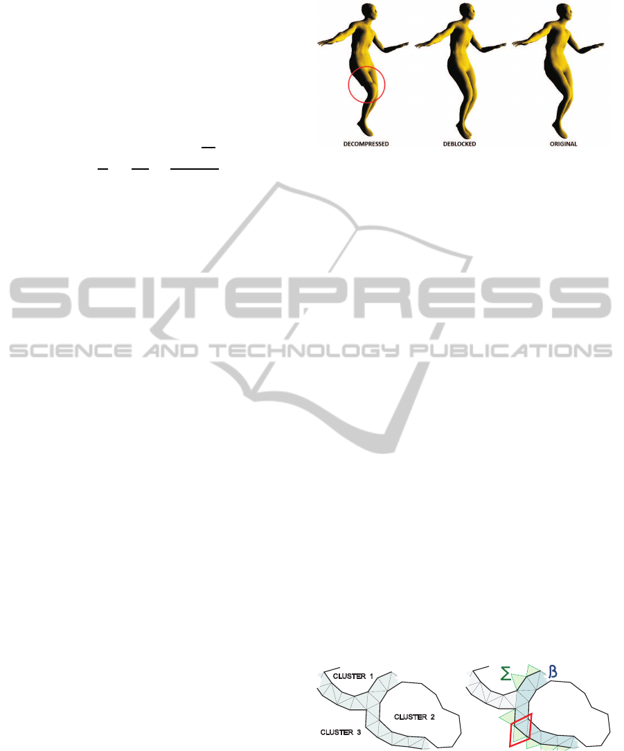
Figure 1: Comparison of decompressed, deblocked and
original frame of the dance animation. 13.6% improvement
of the STED error is achieved by deblocking.
the decompressed mesh. The result of such operation
can be seen in figure 1.
We avoid the deformation of the processed clus-
ter such as mesh smoothing, and thus bringing addi-
tional error to inner vertices of this cluster (not only
on the borders). We believe that a rigid transforma-
tion, which affects all cluster vertices regularly (in
the same way), is a better idea. This transformation
should meet two requirements:
• Minimal dihedral angle between pairs of triangles
on cluster boundaries is required to minimise the
step-like artifacts.
• Reasonable length of edges between clusters.
We can use a combination of the parallelogram
prediction with the rigid transformation to fulfil the
specified requirements and fit the cluster boundaries
better to soften the transitions between them.
3.1 Algorithm Description
The mesh deblocking algorithm starts with finding
edges, that connect borders of different clusters. Tri-
angles containing these edges form a set of border tri-
angles (figure 2), defining areas of mesh distortion de-
scribed earlier and potentially forming step-like arti-
facts between individual clusters.
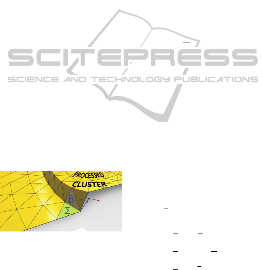
CLUSTER1
CLUSTER3
CLUSTER2
PROCESSED
CLUSTER
W
Figure 2: Left: clusters surrounded by (darkened) border
triangles. Right: green Σ triangles and blue β triangles
surrounding processed cluster forming wedges. One of the
wedges W is highlighted in red.
Next, the best candidate cluster for transforma-
tion (deblocking) is selected. We choose such clus-
GRAPP 2012 - International Conference on Computer Graphics Theory and Applications
52
ter, which can bring the most significant improvement
in the mesh visual quality using a proper rigid trans-
formation. Estimation of this improvement is based
on the width of the surrounding strip of correspond-
ing border triangles β (the distance of the transformed
cluster from the incident clusters).
Estimation of the artifact size reduction is calcu-
lated using an arithmetic average of the lengths of the
edges of the incident border triangles, which are con-
nected to adjacent clusters. Candidates for the de-
blocking transformation are iteratively selected and
transformed while the estimated reduction of artifact
size is decreasing. In other words, when the differ-
ence between two consecutive estimations is lower
than a specified threshold (we choose 0.1% in our ex-
periments), the iterative algorithm stops. Calculation
of an estimation of the artifact size reduction will be
described later in this section.
Once the candidate cluster for the transformation
is selected, the transformation algorithm finds all sur-
rounding triangles Σ from adjacent clusters, which
have one edge in common with any triangle in β.
These Σ triangles are used to form a set of triangle
wedges W consisting of one Σ triangle and one β tri-
angle sharing a common edge, as depicted in figure
2.
In other words, each wedge includes an Σ trian-
gle lying out of the processed candidate cluster, which
can be used for a parallelogram prediction of the posi-
tion of the tip of the β triangle lying on the boundary
of the processed candidate cluster (see figure 3) and
thus wedges can be used for an estimation of position
of the vertices on the boundary of the processed clus-
ter after the desired deblocking transformation.
Figure 3: Green Σ triangle used for parallelogram prediction
of boundary vertex position of the processed cluster after
deblocking transformation.
Now, the position of the boundary vertices of the
processed cluster can be estimated using the parallel-
ogram prediction from clusters surrounding the pro-
cessed candidate cluster.
Parallelogram prediction is used to guarantee a
meaningful length of edges connecting the boundary
of the processed cluster with the rest of the mesh. It
also minimises the dihedral angles between the tri-
angles of the processed cluster and the surrounding
clusters.
A difference vector between the decompressed
position d
i
⊂ D and the predicted position p
i
⊂ P of
the i-th vertex belonging to the boundary of the pro-
cessed cluster is denoted as force f
i
⊂ F and deter-
mines the direction and the distance in which this ver-
tex has to be moved to fulfil the transformation re-
quirements. Each boundary vertex can be affected by
a number of forces and thus the total force vector af-
fecting this vertex is calculated as:
f
i
=
1
M
i
M
i
∑
j=1
(p
j
i
− d
j
i
), (4)
where M
i
denotes the number of forces affecting the
i-th border vertex.
Using this approach, two sets of vertices are ob-
tained. A set of boundary vertices with the original
(decompressed) position D and a set of boundary ver-
tices with the desired position P, p
i
= d
i
+ f
i
, both of
the size of M elements. In the following step of de-
blocking algorithm a rigid transformation of D to P is
calculated. We do not use vertices with no force as-
signed to them in the following calculations, therefore
P, D and F have the same number of elements.
To find the appropriate transformation, we use
SVD-based method of fitting of two 3D point sets de-
scribed in (Arun et al., 1987) obtaining matrix of ro-
tation R and vector of translation t.
In some special cases, the calculation of the ma-
trix of rotation R may fail and thus R does not describe
the rotation we are looking for. In such cases, only the
translation vector t is calculated using the difference
between the centroids of the given sets. The calcula-
tion of the difference between the centroids of D and
P an thus the calculation of the vector of translation
as well is equivalent to the calculation of the average
force vector
f:
t =
1
M
M
∑
i=1
p
i
−
1
M
M
∑
i=1
d
i
=
1
M
M
∑
i=1
(d
i
+ f
i
) −
1
M
M
∑
i=1
d
i
=
1
M
M
∑
i=1
f
i
=
f
(5)
Finally, all vertices d
i
of the processed cluster are
transformed using the rigid transformation obtained
DEBLOCKING FOR DYNAMIC TRIANGLE MESHES
53
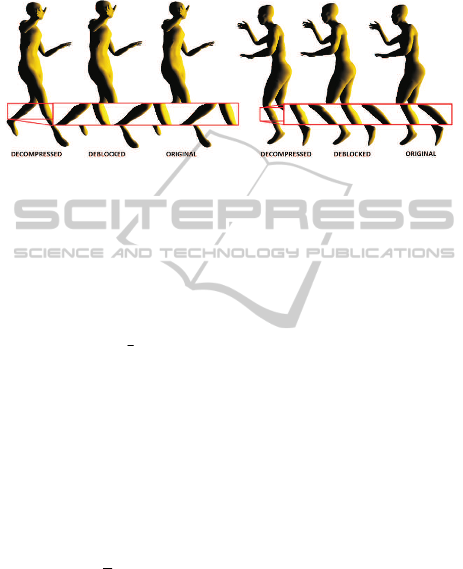
Figure 4: Frames 21 and 45 of the dance animation decompressed, deblocked and compared with the original animation. De-
spite the fact that the animation was compressed quite accurately with about 0.45 bpfv and STED 0.015, the mesh deblocking
brought almost 10% improvement of the STED error of this data.
by the application of SVD on the sets of border ver-
tices O and P. In other words, the whole cluster is ro-
tated and translated in order to minimise the size of
the artifacts on its boundary. The transformed vertex
position ˜p
i
⊂
˜
P close to the predicted vertex position
p
i
of the i-th vertex of the processed cluster is then
calculated as follows:
˜p
i
= R · d
i
+ t (6)
If the calculation of the rotation matrix R fails, the
whole processed cluster is only translated in the di-
rection of average force vector
f. This cluster is dis-
carded from the list of possible candidates for the next
deblocking transformation iteration, because it could
be evaluated as the best candidate for transformation
again without any chance to further improve the vi-
sual quality of the mesh.
Earlier in the text, it was mentioned that the
change of the artifact size related to a given cluster
has to be estimated to identify which cluster should
be transformed to gain probably the most significant
improvement of the visual quality of the mesh in the
current iteration. The estimation algorithm emulates
the transformation algorithm until it reaches the phase
of application of the rigid transformation on all cluster
vertices. Next, the average length l
avg
of force vectors
assigned to boundary vertices of the tested cluster is
computed:
l
avg
=
1
M
M
∑
i=1
| f
i
| (7)
The value of l
avg
is used as an approximation of
the visual quality improvement acquired by the ap-
plication of deblocking transformation on this clus-
ter. This average length value is calculated for each
cluster. The candidate cluster with the largest l
avg
is
chosen as the best candidate for the deblocking trans-
formation.
The whole deblocking algorithm is briefly de-
scribed in the following pseudocode:
repeat
{
select the best candidate cluster for deblocking
-parallelogram prediction of border vertices
-computation of forces in border vertices
-calculation of average force length l_avg
-selection of the best candidate
if(best_l_avg > threshold * last_best_l_avg) break
else store best_l_avg as last_best_l_avg
calculate transformation for selected cluster
-parallelogram prediction of border vertices
-computation of forces in border vertices
-SVD to obtain rotation R and translation t
-if SVD failed, calculate translation t
if(SVD failed) translate cluster using t
else rotate and translate cluster using R and t
}
store deblocked mesh
4 EXPERIMENTAL RESULTS
The approach of the mesh visual quality improve-
ment described in this paper has been implemented
and subsequently, we have measured the impact of the
mesh deblocking on a set of selected dynamic meshes.
During our experiments, we were more interested in
the visual quality of the compressed meshes than in
the error measured by commonly used error metrics,
GRAPP 2012 - International Conference on Computer Graphics Theory and Applications
54
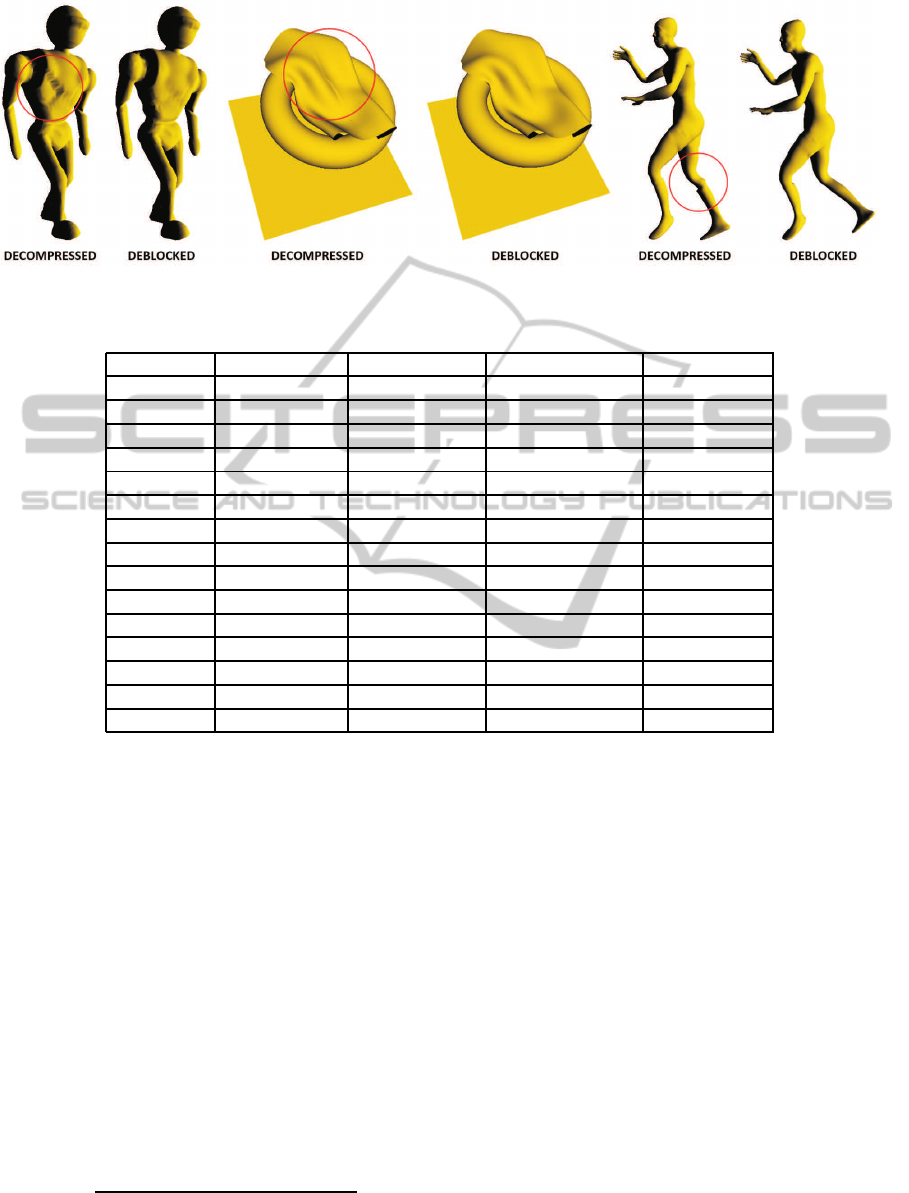
Figure 5: Comparison of meshes decompressed with deblocking and without deblocking.
Table 1: Comparison of results of mesh deblocking.
Animation Bitrate [bpfv] Original Error Deblocked Error Improvement
Chicken 0.1509 0.1311 0.1162 11.32%
0.4467 0.0383 0.0381 0.58%
0.5062 0.0298 0.0307 -3.19%
Cloth 0.1610 0.0620 0.0507 18.22%
0.3319 0.0184 0.0177 3.92%
0.6934 0.0105 0.0103 2.06%
Dance 0.2090 0.0680 0.0606 10.80%
0.2835 0.0448 0.0421 6.09%
0.4300 0.0191 0.0184 3.64%
Humanoid 0.1469 0.1030 0.0986 4.26%
0.3051 0.0268 0.0258 3.92%
0.3914 0.0127 0.0135 -6.32%
Jump 0.1576 0.1204 0.1124 6.65%
0.3308 0.0737 0.0716 2.86%
0.9749 0.0292 0.0292 -0.01%
such as KG-error. Therefore, STED has been chosen
to measure the impact of the mesh deblocking of the
decompressed meshes.
Spatio-temporal edge difference (STED) is a
novel method of measuring error caused by process-
ing of dynamic mesh. It has been derived from results
of a subjective testing of mesh distortion perception
published in (V´aˇsa and Skala, 2011). STED combines
the measurements of spatial and temporal deviation of
edge lengths caused by processing the mesh and it is
focused on local changes of error. The distortion is
evaluated only for a close neighbourhood of each ver-
tex and these values are summed to obtain the overall
error. STED error is defined as a weighted combina-
tion of the spatial error STED
s
and the temporal error
STED
t
:
STED(d, w, dt, c) =
=
q
STED
s
(d)
2
+ c
2
· STED
t
(w, dt)
2
,
(8)
where c is a weighting coefficient, dt is the temporal
distance between consecutive frames, d denotes topo-
logical distance (a vertex is maximally d edges distant
from the given vertex) and w represents the width of
the temporal window.
We tested the mesh deblocking algorithm on sev-
eral 3D dynamic meshes, such as Dance, Chicken and
Jump. These meshes contain only information about
vertex positions for individual frames and connectiv-
ity of their triangles. The experimental data-set con-
sists of artificial animations of single objects, multi-
ple separated objects and scanned real data. We have
experimented with different compression settings as
well. Unlike the original version, the decompressed
meshes processed by mesh deblocking can achieve
lower STED error while maintaining the same bi-
trate. The improvement of the STED error depends
on how precisely the mesh is compressed and thus
on the compression bitrate. A lower bitrate means
more distortion that can be suppressed by the mesh
deblocking. On the other hand, a high bitrate can lead
to a mesh so close to the original that the mesh de-
DEBLOCKING FOR DYNAMIC TRIANGLE MESHES
55

blocking can bring additional error, because it is only
estimating the correct shape of the mesh depending on
the close surroundings of the step-like artifacts. This
case of negative influence of the mesh deblocking
can be handled by additional information appended to
the compressed mesh, defining whether it is advanta-
geous to adjust the mesh by the deblocking algorithm.
Even though the modification of the mesh by de-
blocking affects only a close neighbourhoodof the tri-
angles forming the step-like artifacts between individ-
ual clusters, it can lead to a significant improvement
of STED error and the visual quality of the mesh.
STED error can be decreased by up to 18% using
mesh deblocking, which can lead to a significant im-
provement of visual quality of the mesh as well. It
may happen, that the dynamic mesh is compressed
so precisely that visible cracks or step-like artifacts
caused by clustering appear only in a small subset of
the animation frames (figure 4). Suppressing these
artifacts may lead to a small improvement of STED
error, while significantly improving the visual quality
of the small subset of the frames of animation.
The results of the mesh deblocking for several dif-
ferent dynamic meshes are shown in figure 5. The re-
sults of the selected subset of experiments are given
in table 1. Only results of optimal configurations are
presented in the table. Rate-distortion optimal config-
urations (number of basis vectors, quantisation of ba-
sis vectors and quantisation of feature vectors) were
determined for the clustered Coddyac compression
of dynamic meshes with the deblocking post-process
and without it and compared to each other. There are
sub-optimal configurations with even larger improve-
ment (20%–35%) of the STED error in comparison
with the original (not deblocked) meshes, but it is dif-
ficult to determine the contribution of such compres-
sion configurations which can not be compared with
optimal results derived from the rate-distortion curve.
Note that mesh deblocking becomes inefficient
for compression configurations with bitrate close to
0.5 bpfv (bits per frame and vertex) or higher. The
reason for this behaviour is that the clustered Cod-
dyac compression algorithm is able to compress dy-
namic meshes with almost no distortion using such a
bitrate. Therefore, there is a low probability of the oc-
currence of the step-like artifacts between individual
clusters we are dealing with in this paper. For ex-
ample, the dance animation in figure 4 is compressed
with a bitrate of 0.46 bpfv and contains only 3 or 4
frames that are visibly distorted by the clustered Cod-
dyac compression. Two of these distorted frames are
shown in figure 4. Similarly the dance animation in
figure 1 is compressed with a bitrate of 0.19 bpfv and
contains visible step-like artifacts, but these artifacts
are successfully suppressed by the mesh deblocking.
5 CONCLUSIONS
We have presented a mesh deblocking algorithm
targeted on the reduction of artifacts in clustering-
based mesh compression schemes. We have demon-
strated its efficiency on the example of clustered
Coddyac algorithm and STED error measure for dy-
namic meshes, where we achieve a reduction of the
compression-introduced error by up to 18% without
the need for any additional data. Our result is con-
firmed in the presented images, where the artifact re-
duction is clearly visible. A similar implementation
may be used for post processing of static meshes,
which is also confirmed by our preliminary experi-
ments in this application.
Apart from a thorough testing of the deblocking
process for static meshes, in the future, we also in-
tend to improve the processing speed of our algo-
rithm to allow the real-time processing of very large
meshes. We also intend to perform experiments with
more complex deblocking approaches using a trans-
formation that is smoothly changing across each clus-
ter rather than a rigid one, as in this work. We also
plan to use similar techniques to reduce temporal er-
rors (frame shaking) that may arise in dynamic mesh
processing.
ACKNOWLEDGEMENTS
This work has been supported by the Ministry of Ed-
ucation, Youth and Sports of the Czech Republic un-
der the research program LC-06008 (Center for Com-
puter Graphics).
REFERENCES
Amjoun, R. and Straßer, W. (2007). Efficient compression
of 3d dynamic mesh sequences. Journal of the WSCG.
Arun, K. S., Huang, T. S., and Blostein, S. D. (1987). Least-
squares fitting of two 3-d point sets. IEEE Trans. Pat-
tern Anal. Mach. Intell., 9:698–700.
Desbrun, M., Meyer, M., Schr¨oder, P., and Barr, A. H.
(1999). Implicit fairing of irregular meshes using dif-
fusion and curvature flow. In Proceedings of the 26th
annual conference on Computer graphics and inter-
active techniques, SIGGRAPH ’99, pages 317–324,
New York, NY, USA. ACM Press/Addison-Wesley
Publishing Co.
Kanungo, T., Mount, D. M., Netanyahu, N. S., Piatko,
C. D., Silverman, R., Wu, A. Y., Member, S., and
GRAPP 2012 - International Conference on Computer Graphics Theory and Applications
56

Member, S. (2002). An efficient k-means clustering
algorithm: Analysis and implementation. IEEE Trans-
actions on Pattern Analysis and Machine Intelligence,
24:881–892.
Karni, Z. and Gotsman, C. (2000). Spectral compression of
mesh geometry. In SIGGRAPH, pages 279–286.
Karypis, G. and Kumar, V. (1998). Metis: A software
package for partitioning unstructured graphs, parti-
tioning meshes, and computing fill-reducing orderings
of sparse matrices version 4.0. In University of Min-
nesota, Department of Comp. Sci. and Eng., Army
HPC Research Center, Minneapolis.
Lavou´e, G. (2011). A Multiscale Metric for 3D Mesh Vi-
sual Quality Assessment. Computer Graphics Forum
(Proceedings of Eurographics Symposium on Geome-
try Processing 2011), 30.
Lavou´e, G., Drelie Gelasca, E., Dupont, F., Baskurt, A., and
Ebrahimi, T. (2006). Perceptually driven 3D distance
metrics with application to watermarking. In SPIE Ap-
plications of Digital Image Processing XXIX.
Lengyel, J. E. (1999). Compression of time-dependent ge-
ometry. In In I3D 99: Proceedings of the 1999 sympo-
sium on Interactive 3D graphics, pages 89–95. ACM.
Mamou, K., Zaharia, T. B., and Prˆeteux, F. J. (2008). Famc:
The mpeg-4 standard for animated mesh compression.
In ICIP, pages 2676–2679.
Marpe, D., Schwarz, H., Blttermann, G., Heising, G., and
Wieg, T. (2003). Context-based adaptive binary arith-
metic coding in the h.264/avc video compression stan-
dard. IEEE Transactions on Circuits and Systems for
Video Technology, 13:620–636.
M¨uller, K., Smolic, A., Kautzner, M., Eisert, P., and Wie-
gand, T. (2005). Predictive compression of dynamic
3d meshes. In ICIP (1), pages 621–624.
Rossignac, J. (1999). Edgebreaker: Connectivity compres-
sion for triangle meshes. IEEE Transactions on Visu-
alization and Computer Graphics, 5:47–61.
Rus, J. and V´aˇsa, L. (2010). Analysing the influence of ver-
tex clustering on pca-based dynamic mesh compres-
sion. In Articulated Motion and Deformable Objects,
pages 55–66, Heidelberg. Springer.
Sattler, M., Sarlette, R., and Klein, R. (2005). Simple
and efficient compression of animation sequences.
In SCA ’05: Proceedings of the 2005 ACM SIG-
GRAPH/Eurographics symposium on Computer ani-
mation, pages 209–217. ACM Press.
V´aˇsa, L. and Skala, V. (2007). Coddyac: connectivity
driven dynamic mesh compression. In 3DTV-CON
2007, pages 1–4, Piscataway. IEEE.
V´aˇsa, L. and Skala, V. (2009). Cobra: Compression of
the basis for pca represented animations. Computer
Graphics forum, 28(6):1529–1540.
V´aˇsa, L. and Skala, V. (2011). A perception corre-
lated comparison method for dynamic meshes. IEEE
Transactions on Visualization and Computer Graph-
ics, 17(2):220–230.
Wang, Z., Bovik, A. C., Sheikh, H. R., and Simoncelli, E. P.
(2004). Image quality assessment: From error visibil-
ity to structural similarity. IEEE TRANSACTIONS ON
IMAGE PROCESSING, 13(4):600–612.
Zhang, J. and Owen, C. B. (2004). Octree-based animated
geometry compression. In Data Compression Confer-
ence’04, pages 508–520.
DEBLOCKING FOR DYNAMIC TRIANGLE MESHES
57
