
A STEREOSCOPIC AUGMENTED REALITY SYSTEM
FOR THE VERIDICAL PERCEPTION OF THE 3D SCENE LAYOUT
M. Chessa, M. Garibotti, A. Canessa, A. Gibaldi, S. P. Sabatini and F. Solari
The Physical Structure of Perception and Computation Group, University of Genoa, Genoa, Italy
Keywords:
Stereoscopic Display, Virtual Reality, 3D Visualization, Head Tracking, 3D Position Judgment, Shape
Perception, Human and Computer Interaction.
Abstract:
The recent diffusion of the stereoscopic 3D technologies has yielded the development of affordable and of
everyday use devices for the visualization of such information. This has paved the way for powerful human
and computer interaction systems based on augmented reality environment where humans can interact with
both virtual and real tools. However, an observer freely moving in front of a 3D display could experience a
misperception of the depth and of the shape of virtual objects. Such distortions can have serious consequences
in scientific and medical fields, where a veridical perception is required, and they can cause visual fatigue
in consumer and entertainment applications. Here, we propose a novel augmented reality system capable to
correctly render 3D virtual objects, without adding significant delay, to an observer that changes his position
in the real world and acts in the virtual scenario. The correct perception of the scene layout is assessed through
two experimental sessions with several observers.
1 INTRODUCTION
In the last decade, there has been a rapidly growing
interest in technologies for presenting stereo 3D im-
agery both for professional applications, e.g. scien-
tific visualization, medicine and rehabilitation system
(Subramanian et al., 2007; Ferre et al., 2008; Knaut
et al., 2009), and for entertainment applications, e.g.
3D cinema and videogames (Kratky, 2011).
With the diffusion of 3D stereo visualization tech-
niques, researchers have investigated the benefits and
the problem associated with them. Several studies
devised some specific geometrical parameters of the
stereo acquisition setup (both actual and virtual) in
order to induce the perception of depth in a human
observer (Grinberg et al., 1994). In this way, we can
create stereo pairs that are displayed on stereoscopic
devices for human observers which do not introduce
vertical disparity, and thus causing no discomfort to
the users (Southard, 1992). Yet, other factors, re-
lated to spatial imperfections of the stereo image pair,
that yield visual discomfort have been addressed. In
(Kooi and Toet, 2004) the authors experimentally de-
termined the level of discomfort experienced by a
human observer viewing imperfect binocular image
pairs, with a wide range of possible imperfections and
distortions. Moreover, in the literature there are seve-
ral works that describe the difficulty of perceptually
rendering a large interval of 3D space without a visual
stress, since the eyes of the observer have to maintain
accommodation on the display screen (i.e., at a fixed
distance), thus lacking the natural relationship be-
tween accommodation and vergence eye movements,
and the distance of the objects (Wann et al., 1995).
The vergence-accommodation conflict is out of the
scope of this paper, however for a recent review see
(Shibata et al., 2011).
Besides the previously cited causes of discom-
fort, another well-documented problem is that the 3D
shape and the scene layout are often misperceived
by a viewer freely positioned in front of stereoscopic
displays (Held and Banks, 2008). Only few works
in the literature address the problem of examining
depth judgment in augmented or virtual reality envi-
ronments in the peripersonal space (i.e. distances less
than 1.5 m). Among them, (Singh et al., 2010) in-
vestigated depth estimation via a reaching task, but in
their experiment the subjects could not freely move in
front of the display. Moreover, only correcting meth-
ods useful in specific situation, e.g. see (Lin et al.,
2008; Vesely et al., 2011), or complex and expensive
systems (Cruz-Neira et al., 1993) are proposed in the
literature. Nevertheless, to the knowledge of the au-
thors, there are no works that aim to quantitatively
15
Chessa M., Garibotti M., Canessa A., Gibaldi A., P. Sabatini S. and Solari F..
A STEREOSCOPIC AUGMENTED REALITY SYSTEM FOR THE VERIDICAL PERCEPTION OF THE 3D SCENE LAYOUT.
DOI: 10.5220/0003831600150023
In Proceedings of the International Conference on Computer Vision Theory and Applications (VISAPP-2012), pages 15-23
ISBN: 978-989-8565-04-4
Copyright
c
2012 SCITEPRESS (Science and Technology Publications, Lda.)
analyze the 3D shape distortions, their consequences
on the perception of the scene layout, and to propose
an effective and general solution for an observer that
freely moves in front of a 3D monitor.
In entertainment applications, such distortions
might not be a serious problem, even if they can cause
visual fatigue and stress, but in medical and surgery
applications, or in cognitive rehabilitation system and
in applications for the study of the visuo-motor co-
ordination, they can have serious implications. This
is especially true in augmented reality (AR) applica-
tions, where the user perceives real and virtual stimuli
at the same time, thus it is necessary that the rendering
of the 3D information does not introduce undesired
distortions.
In this paper, we propose an AR system capable
to minimize the 3D shape misperception problem that
arises when the viewer changes his/her position with
respect to the screen, thus yielding a natural interac-
tion with the virtual environment. The performances
of the developed system are quantitatively assessed
and compared to the results obtained by using a con-
ventional system, through experimental sessions with
the aim of measuring the user’s perception of the 3D
shape and the effectiveness of his/her interaction in
the AR environment.
The paper is organized as follow: in Section 2
we describe the geometry of the standard stereoscopic
3D rendering technique, the misperception associated
with the movements of the observer, and our solution;
Section 3 describes the AR system we have devel-
oped; Section 4 presents two experimental sessions
to validate the proposed approach; the conclusion and
future work are discussed in Section 5.
2 THE GEOMETRY OF THE
STEREOSCOPIC 3D
RENDERING TECHNIQUE
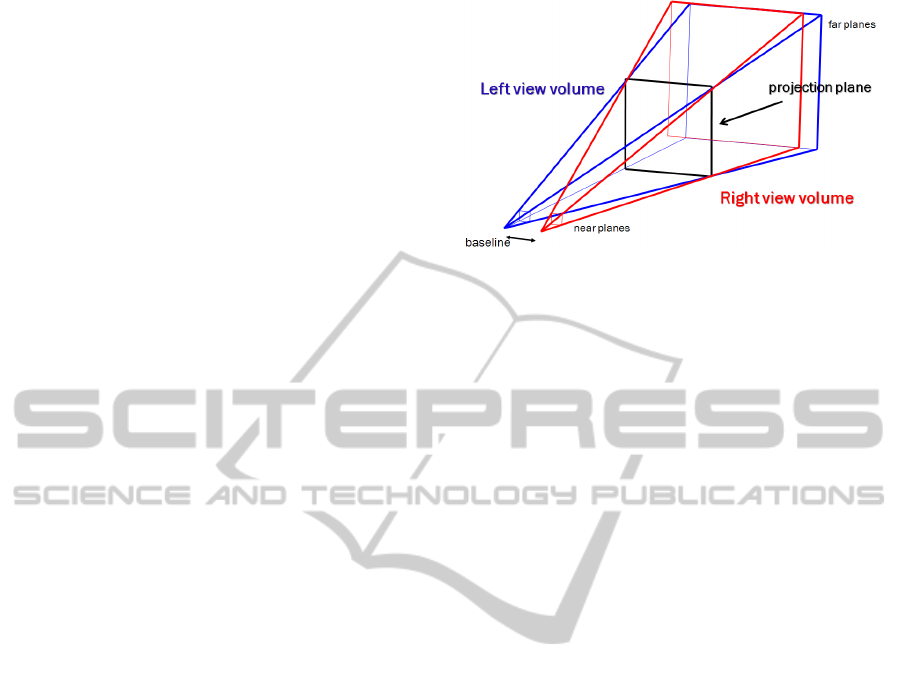
2.1 The Standard Approach
To create the stereo 3D stimuli for the conventional
approach, we have adopted the stereo rendering, that
uses the method known as “parallel axis asymmetric
frustum perspective projection”, or off-axis technique
(Bourke and Morse, 2007; Grinberg et al., 1994), the
technique usually used to generate a perception of
depth for a human observer. In the off-axis technique,
the stereo images are obtained by projecting the ob-
jects in the scene onto the display plane for each cam-
era; such projection plane has the same position and
orientation for both camera projections (see Fig. 1).
Figure 1: The two skewed frustums for the off-axis tech-
nique.
We have also taken into account the geometrical
parameters necessary to correctly create stereo pairs
displayed on stereoscopic devices for human observer
(Grinberg et al., 1994). In particular:
- the image planes have to be parallel;
- the optical points should be offset relative to the
center of the image;
- the distance between the two optical centers have
to be equal to the interpupillary distance;
- the field of view of the cameras must be equal to
the angle subtended by the display screen;
- the ratio between the focal length of the cameras
and the viewing distance of the screen should be
equal to the ratio between the width of the screen
and of the image plane.
Moreover, as in (Kooi and Toet, 2004), one should
take into account the problem of spatial imperfection
that could cause visual discomfort to the user, such as:
- crosstalk, that is a transparent overlay of the left
image over the right image and vice versa;
- blur, that is different resolutions of the stereo im-
age pair.
The previously mentioned rules are commonly
considered when designing stereoscopic virtual re-
ality systems. Nevertheless, when looking at a vir-
tual scene, in order to obtain a veridical perception of
the 3D scene layout, it is necessary that the observer
must be positioned in the same position of the virtual
stereo camera. If the observer is in the correct po-
sition, then the retinal images, originated by viewing
the 3D stereo display and the ones originated by look-
ing at the real scene, are identical (Held and Banks,
2008). If this constraint is not satisfied, a mispercep-
tion of the object’s shape and of the depth occurs (see
Fig. 2(a) and Fig. 3).
VISAPP 2012 - International Conference on Computer Vision Theory and Applications
16
projection plane
screen
left image
right image
virtual stereo camera
misperceived
target
observer
target
misperceived
target
observer
observer
perceived
target
projection plane
screen
left image
right image
virtual stereo camera
target
observer
perceived
target
(a) (b)
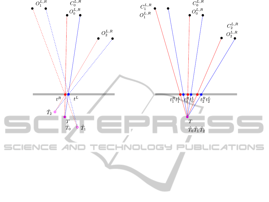
Figure 2: A sketch of geometry of the stereoscopic augmented reality environment when using the standard stereo rendering
technique (a), and when using the proposed approach (b). (a) In the virtual environment a target is positioned in T, and a
stereo camera is placed inC
L,R
0
, thus generating the left and right projections t
L
and t
R
on the projection plane. A real observer
in the same position O
L,R
0
of the virtual camera will perceive the target correctly, whereas he will misperceive the position (
ˆ
T
1
and
ˆ
T
2
) of the target when looking at the screen from different positions (O
L,R
1
and O
L,R
2
). (b) In the proposed technique, the
virtual camera is moved accordingly to the different positions of the observer. This yields different projections of the target
(t
L
0
, t
R
0
; t
L
1
, t
R
1
; t
L
2
, t
R
2
) on the projection plane, thus allowing a coherent perception of the target for the observer.
2.2 The Proposed Approach
In Figure 2(a), a virtual stereo camera positioned in
C
0
(for the sake of simplicity, we omit the superscript,
i.e. C
L
0
and C
R
0
denote the positions of the left and
right cameras, respectively) determines the left and
right projections t
L
and t
R
of the target T on the pro-
jection plane. An observer located in the same po-
sition of the virtual camera (O
0
= C
0
) will perceive
the target in a position
ˆ
T
0
coincident with the true po-
sition. Otherwise, an observer located in a different
position (O
i
6= C
0
) will experience a misperception of
the location of the target (
ˆ
T
i
6= T). This also causes
a deformation of the 3D shape, as it is schematically
shown in Figure 3 for a simple target represented by
a horizontal bar. When the observer is in a location
different from the position of the virtual camera, he
misperceives both the depth of the object and its spa-
tial structure.
To overcome this problem, the system we have de-
veloped, and that we present in this paper, is capable
of compensating for the movement of the observer by
computing his/her position with respect to the moni-
tor, and consequently moving the virtual stereo cam-
era (see Fig. 2(b)). For each different position of the
observer a corresponding stereo image pair is gener-
ated, and displayed on the screen. Thus, the observer
always perceives the 3D shape of the objects coher-
ently. Moreover, to maintain a consistent augmented
reality environment it is necessary to have a virtual
world that is at each moment a virtual replica of the
real world. Thus, the screen and the projection plane
should be always coincident.
3 THE PROPOSED AUGMENTED
REALITY SYSTEM
3.1 Software and Hardware
Components
Considering the availability of commercial products
with high performances and affordable costs, we de-
cided to use off-the-shelf devices to design and de-
velop our AR system. Specifically, we use the Xbox
Kinect, a motion sensing input device developed by
Microsoft for the Xbox 360 video game console.
A STEREOSCOPIC AUGMENTED REALITY SYSTEM FOR THE VERIDICAL PERCEPTION OF THE 3D SCENE
LAYOUT
17

projection plane
screen
left image
right image
virtual stereo camera
observer
observer
misperceived
target
observer
target
misperceived
target
Figure 3: The deformation of the 3D shape when displaying
a horizontal bar with the standard technique. For a compar-
ison with the experimental results see Fig. 7(b).
Based on an RGB camera and on an infrared (IR)
depth sensor, this RGB-D device is capable of pro-
viding a full-body 3D motion capture. The depth
sensor consists of an IR projector combined with a
monochrome camera.
The main features of this device used for the de-
velopment of the system are:
- Frame rate: 30 Hz;
- Depth image size: VGA (640×480);
- Depth resolution: 1 cm at 2 m distance from the
sensor;
- Operation range: from 0.6 m to 3.5 m;
- Color image size: VGA (640×480);
- Horizontal Field of View: 58 deg.
All the software modules are developed in C++,
using Microsoft Visual Studio 10. To render the
stereoscopic virtual scene in quad buffer mode we use
the Coin3D graphic toolkit
1
, a high level 3D graphic
toolkit for developing cross-platform real time 3D vi-
sualization. To access the data provided by Microsoft
XBox Kinect, we use the open source driver (version
5.0.3.3), released by PrimeSense
2
, the company that
developed the 3D technology of the Kinect. The lo-
calization and the tracking of the head and the hand
rely on the framework OpenNI
3
(version 1.3.2.1), a
set of open source Application Programming Inter-
faces (APIs). These APIs provide support for access
1
www.coin3D.org
2
www.primesense.com
3
www.openni.org
to natural interaction devices, allowing the body mo-
tion tracking, hand gestures and voice recognition.
The processing of the images acquired by Kinect
RGB camera is performed through the OpenCV 2.3
4
library.
Both the development and the testing phases have
been conducted on a PC equipped with an Intel Core
i7 processor, 12 GB of RAM, a Nvidia Quadro 2000
video card enabled to 3D Vision Pro with 1 GB of
RAM, and a Acer HN274H 3D monitor 27-inch.
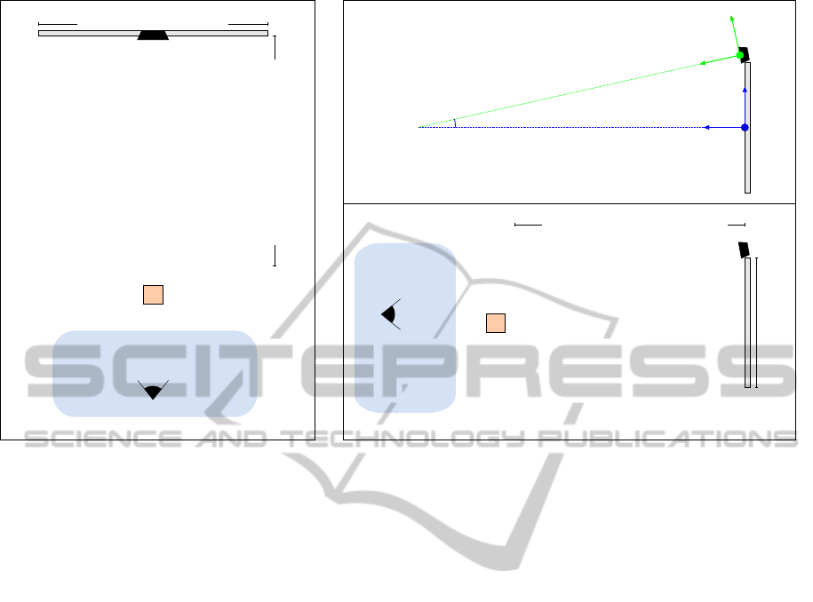
3.2 System Description
Figure 4 shows the setup scheme of our system. The
XBox Kinect is located on the top of the monitor, cen-
tered on the X axis, and slightly rotated around the
same axis. This configuration was chosen because
it allows the Kinect to have good visibility on the
user, without having the Kinect interposed between
the user and the monitor. To align the two coordinate
systems, we performed a calibration step by taking
into consideration a set of world points, whose co-
ordinates are known with respect to the monitor co-
ordinate system, and their positions acquired by the
Kinect. In this way, it is possible to obtain the angle
α
y
between the Y axis of the Kinect coordinate sys-
tem and the monitor one. In the setup configuration
considered for the experiments presented in Section 4
the value of α
y
is about 8 deg.
The proposed system, during the startup phase, is
responsible to recognize and track the position of the
skeleton of the user. After the startup phase, each time
new data is available from the Kinect, the system per-
forms a series of steps to re-compute the representa-
tion of the 3D virtual world, and to achieve the inter-
action with the user. These steps can be summarized
as follows:
- Positioning of the stereo camera of the virtual
world in the “tracked” position of the user’s head,
obtained from the Kinect. The stereo camera has
a fixed angle of view, far wider than the one that is
created between the real user and the monitor, that
is his/her “window” on the virtual world. For this
reason, once repositioned the camera, our system
changes the viewport to display on the monitor
only the portion of the virtual world that the cam-
era sees through the area that represents the mon-
itor in the virtual world. Just as if we are looking
through a window.
- Detection of the position of the index finger of the
user, through a light marker, in the image plane
of the Kinect RGB camera. This can be achieved
4
opencv.willowgarage.com
VISAPP 2012 - International Conference on Computer Vision Theory and Applications
18
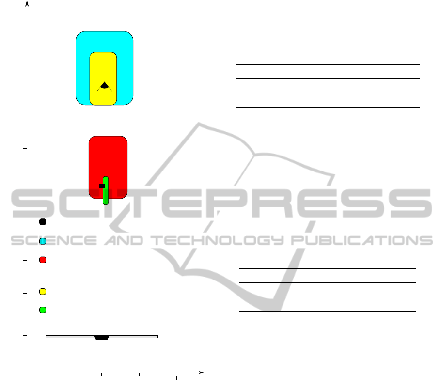
Target
Position: 0, 0, 800 mm
movement area
of the observer
Monitor Width: 600 mm
Minimum Distance: 600 mm
Side View
Monitor
Coordinate System
Kinect
Coordinate System
ZY plane
angle αy = 8°
Monitor Height: 340 mm
movement area
of the observer
Target
Position: 0, 0, 800 mm
Minimum Distance: 600 mm
Top View
ZX plane
Figure 4: The developed setup for the augmented reality system. The reported measures refer to the specific setup considered
for the experimental results. The position of the target is the same of the one of the experiment shown in Figure 5.
first by obtaining the position of the hand from the
skeleton, produced by OpenNI libraries, and then
performing a segmentation and a tracking of the
light source in the sub-image, centered in the de-
tected position of the hand. This image processing
step is based on the color information, and is per-
formed by using OpenCV libraries.
- Computation of the position of the finger in the
real world by combining its position in the im-
age plane and the corresponding depth (from the
Kinect D camera). The spatial displacement be-
tween the RGB and D cameras has been taken into
account.
The computed 3D position both of the head and of
the finger have been stabilized and smoothed in time
through a small averaging window over 5 frames.
In order to evaluate the precision of the measure-
ments of the system we performed a test session, from
which we derived an uncertainty of about 1 cm (at 1 m
of distance from the sensor) on the three axes in real
world coordinates, both for the head and the finger
localization.
4 EXPERIMENTS AND RESULTS
To quantitatively assess the proposed augmented re-
ality system, and to verify if it effectively allows a
veridical perception of the 3D shape and a better inter-
action with the user, we have performed two types of
experiments. In the first one, the observer was asked
to reach a virtual target (i.e. the nearest right bottom
vertex of a frontal cube whose width is 2.5 cm), in
the second one, the task was to trace the profile of
a virtual horizontal bar. In both cases, the scene has
been observed by different positions, and we have ac-
quired the position of the head and of the finger dur-
ing the execution of the tasks. The experiments have
been performed both by using a standard rendering
technique (in the following denoted as tracking OFF)
and the proposed approach that actively modifies the
rendered images with respect to the position of the
observer’s head (in the following denoted as tracking
ON). The virtual scenes have been designed in order
to minimize the effects of the depth cues other than
the stereoscopic cue, such as shadows and perspec-
tive. It is worth noting that since we use a real finger
to estimate the perceived depth of a virtual object, we
obtain a veridical judgment of the depth. If the task is
performed by using a virtual finger (a virtual replica
of the finger), we obtain a relative estimation of the
depth, only.
For the experiments six subjects were chosen,
with ages ranging from 28 to 44. All participants
(males and females) had normal or corrected-to-
normal vision. Each subject performed the two tasks
looking at the scene from 5 different positions both in
A STEREOSCOPIC AUGMENTED REALITY SYSTEM FOR THE VERIDICAL PERCEPTION OF THE 3D SCENE
LAYOUT
19
-300 -200 -100 0 100 200 300
-200
-150
-100
-50
0
50
100
-2000200
600
800
1000
1200
1400
1600
1800
X [mm]
Z [mm]
Y [mm]
X [mm]
Target
Head position with tracking ON
Head position with tracking OFF
Perceived position of the target with tracking OFF
Perceived position of the target with tracking ON
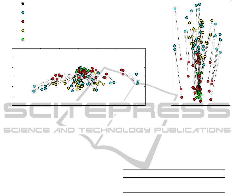
Figure 5: Perceived positions of the target point, and the related head positions for the reaching task. The perceived positions
of the target with our tracking system enabled (green circles) are less scattered than the ones using a conventional system (red
circles).
tracking ON and in tracking OFF mode.
4.1 First Experiment: 3D Position
Judgment
Figure 5 shows the results of the first experiment.
When the tracking is ON, the positions of the
observer’s head (represented by yellow circles) are
spread in a smaller range than the positions acquired
when the tracking is OFF (represented by cyan cir-
cles). This happens since, as a consequence of the ac-
tive modification of the point of view, the target could
not be visible from lateral views. This behaviour is
consistent with real world situations, in which objects
that are seen through a window disappear when the
observer moves laterally. Nevertheless, the perceived
target points when the tracking is ON (green circles)
are less scattered than the perceived positions of the
target point when the tracking is OFF (red circles),
also taking into account the more limited movements
of the observer in the first situation.
Table 1 shows the mean errors and their standard
deviations of the perceived points. The tracking of the
head position of the observer and the re-computation
of the stereo pairs projected onto the screen, per-
formed by our system, yield a consistent reduction in
the error of the perceived position of the target and in
its standard deviation.
A graphic representation of the scattering areas of
the perceived points with respect to the movements of
Table 1: The mean error and the standard deviation values
(expressed in mm) of the perceived position of the target
for the first experiment. The actual position of the target is
(12.5, −12.5, 812.5).
X Y Z
tracking OFF 81±68 22±16 146±119
tracking ON 14±10 6±5 74±43
the observer in the two situations is shown in Figure 6.
It is worth noting that the area where the target
is perceived, when our tracking system is enabled,
is very small, thus indicating a veridical perception
of the virtual object. In particular, when the track-
ing is OFF, the mean and the standard deviation val-
ues of the perceived 3D points, expressed in mm, are
(34 ± 104, −34 ± 17, 898 ± 168), whereas we obtain
(21 ± 15, −17 ± 6, 774± 76) with the tracking ON.
Since the positions of the observers are uniformly dis-
tributed in the work space, the perceived positions of
the target are uniformly distributed around the actual
target position (see Fig. 2), thus yielding mean values
comparable between the two systems. The misper-
ception is represented by the spread of the perceived
positions of the target, that it can be quantified by the
standard deviation values.
VISAPP 2012 - International Conference on Computer Vision Theory and Applications
20
Z [mm]
X [mm]
1400
1200
1600
1000
800
600
400
200
0
0-200 200 400
Target
Head position with tracking ON
Head position with tracking OFF
Perceived position of the target
with tracking OFF
Perceived position of the target
with tracking ON
Figure 6: Graphic representation of the results of the first
experiment. The boxes are centered in the mean values of
the head positions and of the perceived positions of the tar-
get. The size of the boxes is represented by the standard
deviation values. The smaller size of the green box repre-
sents a veridical perception (i.e. without misperception) of
the position of the target.
4.2 Second Experiment: Shape
Perception
Figure 7 shows the perceived start and end points of
the bar traced in the second experiment.
The considerations on the positions of the head
done for the previous experiment are still valid. When
our system is enabled, the perceived positions of the
bar are less scattered than in the conventional system.
This is confirmed by the mean error and the standard
deviation values of the perceived mid point of the bar,
shown in Table 2.
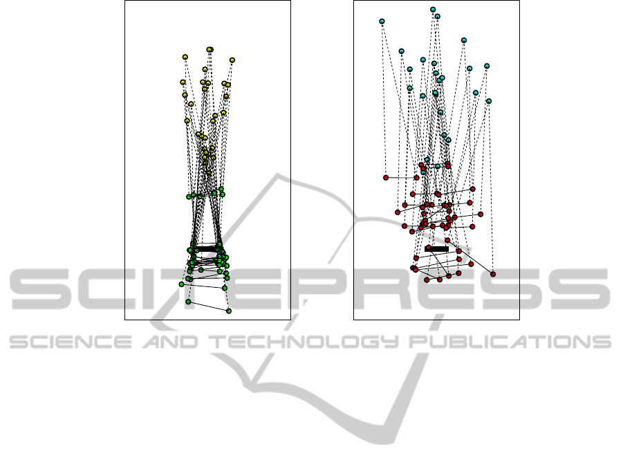
Table 2: The mean error and the standard deviation values
(expressed in mm) of the perceived mid point of the hori-
zontal bar for the second experiment. The actual position of
the mid point of the target bar is (0, 0, 800).
X Y Z
tracking OFF 47±47 26±29 149±88
tracking ON 9±6 13±8 76±73
Moreover, when the tracking is OFF, the observer
misperceives the orientation of the horizontal bar, as
we have previously discussed (see Fig. 3). Table 3
confirms that with the proposed system the mean er-
ror and the standard deviation of the perceived orien-
tation of the bar are reduced. The same applies for the
perceived length of the bar.
Table 3: The mean error and the standard deviation values
of the perceived length and orientation (angle with respect
to the horizontal bar) for the second experiment. The actual
length of the target bar is 100 mm, and the orientation is
0 deg.
length (mm) angle (deg)
tracking OFF 36±38 11±13
tracking ON 26±22 7±5
5 CONCLUSIONS AND FUTURE
WORK
A novel stereoscopic augmented reality system has
been developed and presented in this paper. Such sys-
tem allows a coherent perception of both virtual and
real objects to an user acting in a virtual environment,
by minimizing the misperception of the depth and of
the 3D layout of the scene. This is achieved through
a continuous tracking of the position of the observer
and a consequent re-computing of the left and right
image pair displayed on the screen.
In the conventional systems, when the user freely
moves in front of the screen, distortions of the shape
and of the distance of virtual objects occur. This is-
sue is relevant when an accurate interaction of a real
observer in a virtual world is required, especially in
scientific visualization, rehabilitation systems, or in
psychophysical experiments.
The proposed system relies on off-the-shelf tech-
nologies (i.e., Microsoft XBox Kinect for the track-
ing, and a 3D monitor with shutter glasses for the ren-
dering) and it allows a natural interaction between the
A STEREOSCOPIC AUGMENTED REALITY SYSTEM FOR THE VERIDICAL PERCEPTION OF THE 3D SCENE
LAYOUT
21
-2000200
600
800
1000
1200
1400
1600
1800
Z [mm]
X [mm]
-2000200
600
800
1000
1200
1400
1600
1800
Z [mm]
X [mm]
(a) (b)
Figure 7: Perceived positions of the target horizontal bar, and the related head positions (denoted by the yellow and cyan
circles for tracking ON and tracking OFF, respectively) for the tracing task. The perceived positions of the end-points of the
target bar with our tracking system enabled (green circles) are closer to the actual values, than the ones obtained by using a
conventional system (red circles).
user and the virtual environment, without adding sig-
nificant delay in the rendering process.
The performances of the developed augmented re-
ality system has been assessed by a quantitative anal-
ysis in reaching and tracing tasks. The results have
been compared with the ones obtained by using a con-
ventional system that does not track the position of the
head. The results confirmed a better perception of the
depth and of the 3D scene layout with the proposed
system.
As a future work, we plan to improve the tech-
niques used to render the stereoscopic environment
and to track the user in the scene. Moreover, in order
to further validated the proposed system, an extensive
experimental phase is foreseen, with a larger number
of participants and with different tasks.
ACKNOWLEDGEMENTS
This work has been partially supported by “Progetto
di Ricerca di Ateneo 2010”, and by National Project
“PRIN 2008”.
REFERENCES
Bourke, P. and Morse, P. (2007). Stereoscopy: Theory and
practice. Workshop at 13th International Conference
on Virtual Systems and Multimedia.
Cruz-Neira, C., Sandin, D., and DeFanti, T. (1993).
Surround-screen projection-based virtual reality: the
design and implementation of the cave. In Pro-
ceedings of the 20th annual conference on Computer
graphics and interactive techniques, pages 135–142.
Ferre, P., Aracil, R., and Sanchez-Uran, M. (2008). Stereo-
scopic human interfaces. IEEE Robotics & Automa-
tion Magazine, 15(4):50–57.
Grinberg, V., Podnar, G., and Siegel, M. (1994). Geome-
try of binocular imaging. In Proc. of the IS&T/SPIE
Symp. on Electronic Imaging, Stereoscopic Displays
and applications, volume 2177, pages 56–65.
Held, R. T. and Banks, M. S. (2008). Misperceptions in
stereoscopic displays: a vision science perspective. In
Proceedings of the 5th symposium on Applied percep-
tion in graphics and visualization, APGV ’08, pages
23–32.
Knaut, L. A., Subramanian, S. K., McFadyen, B. J., Bour-
bonnais, D., and Levin, M. F. (2009). Kinematics of
pointing movements made in a virtual versus a phys-
ical 3-dimensional environment in healthy and stroke
VISAPP 2012 - International Conference on Computer Vision Theory and Applications
22

subjects. Archives of Physical Medicine and Rehabil-
itation, 90(5):793 – 802.
Kooi, F. and Toet, A. (2004). Visual comfort of binocular
and 3D displays. Displays, 25(2-3):99–108.
Kratky, A. (2011). Re-viewing 3D implications of the latest
developments in stereoscopic display technology for a
new iteration of 3D interfaces in consumer devices. In
Advances in New Technologies, Interactive Interfaces,
and Communicability, volume 6616 of Lecture Notes
in Computer Science, pages 112–120. Springer Berlin
/ Heidelberg.
Lin, L., Wu, P., Huang, J., and Li, J. (2008). Precise depth
perception in projective stereoscopic display. In Young
Computer Scientists, 2008. ICYCS 2008. The 9th In-
ternational Conference for, pages 831 –836.
Shibata, T., Kim, J., Hoffman, D. M., and Banks, M. S.
(2011). The zone of comfort: Predicting visual
discomfort with stereo displays. Journal of Vision,
11(8):1 – 29.
Singh, G., Swan, II, J. E., Jones, J. A., and Ellis, S. R.
(2010). Depth judgment measures and occluding sur-
faces in near-field augmented reality. In APGV ’10,
pages 149–156. ACM.
Southard, D. (1992). Transformations for stereoscopic vi-
sual simulation. Computers & Graphics, 16(4):401–
410.
Subramanian, S., Knaut, L., Beaudoin, C., McFadyen, B.,
Feldman, A., and Levin, M. (2007). Virtual reality
environments for post-stroke arm rehabilitation. Jour-
nal of NeuroEngineering and Rehabilitation, 4(1):20
– 24.
Vesely, M., Clemens, N., and Gray, A. (2011). Stereo-
scopic images based on changes in user viewpoint. US
2011/0122130 Al.
Wann, J. P., Rushton, S., and Mon-Williams, M. (1995).
Natural problems for stereoscopic depth perception in
virtual environments. Vision research, 35(19):2731–
2736.
A STEREOSCOPIC AUGMENTED REALITY SYSTEM FOR THE VERIDICAL PERCEPTION OF THE 3D SCENE
LAYOUT
23
