
TandemStack
A Flexible and Customizable Sensor Node Platform for Low Power Applications
Oliver Stecklina
1
, Dieter Genschow
1
and Christian Goltz
2
1
IHP GmbH, Im Technologiepark 25, 15236 Frankfurt (Oder), Germany
2
BTU Cottbus, Konrad-Wachsmann-Allee 1, 03046 Cottbus, Germany
Keywords:
Motes, Sensor Node, Wireless Sensor Networks, Low Power, Low Cost, Micro-controller, Transceiver.
Abstract:
Wireless sensor nodes are becoming more and more considered for a wide variety of application scenarios. But
by going into real world scenarios requirements becomes more complex and must be covered more accurate.
Furthermore, these requirements must be met by a development process that is driven by the factors of cost and
time. Reusing components is a promising way to make such a development process more efficient. We present
a flexible and customizable sensor node platform which follows the objective to assemble as few functional
units as possible on a single Printed Circuit Board (PCB). The PCBs are connected by a standardized board-
to-board connector, which makes a free ordering and mixture of different modules possible. We will show that
by using a standardized Mote Component Interconnect (MCI) an extension as well as an adaption of a sensor
node to new scenarios becomes feasible by adding or replacing single platform components. The presented
sensor node platform allows a fast and inexpensive development process as it is necessary for current and
upcoming real word applications.
1 INTRODUCTION
Wireless Sensor Network (WSN)s become more and
more common in a wide variety of application sce-
narios. They are used for controlling industrial in-
frastructures, urban and environmental monitoring as
well as home-care applications. Along with their
growing use cases a flexible sensor node platform is
needed to meet upcoming and changing requirements
in a fast and cost-efficient way.
The flexibility of the ubiquitous Personal Com-
puter (PC) architecture with standardized buses is an
important factor for its triumphal procession. A mod-
ern PC can be easily and cost-efficiently extended or
adapted to new or changing requirements by replac-
ing or adding expansion cards. Furthermore, stan-
dardized buses open the opportunity to setup systems
with components from many different manufacturers.
We state that a standardized interface for mote com-
ponents can reduce the development costs and time
for mote’s hardware and software significantly. In this
paper we present a flexible and customizable mote
platform that follows the objective to combine only
tightly coupled components on a single PCB. The dif-
ferent modules will be connected by a uniform Mote
Component Interconnect (MCI), which allows a new
freedom in combination. We will introduce some re-
strictions to ensure the interoperability of modules
and present concepts for routing buses or point-to-
point links over a uniform interface.
In the next section we will introduce a set of
more or less well-known commercially available sen-
sor nodes. All these motes are designed for low
power WSNs without real application backgrounds.
But their inflexible architectures limit their applica-
tion fields significantly. In the following we present
our TandemStack platform. We introduce the MCI,
which allows a free ordering of modules. In section
5 we compare our design with a selection of motes of
section 2. Finally we describe three application sce-
narios where our TandemStack is already used. After
that we will conclude the paper with a short outlook.
2 MOTE PLATFORMS
We can identify three different types of low power
motes. The first type uses a single PCB and is
equipped with the basic mote components: Micro
Controller Unit (MCU), transceiver, storage, sensors
and power supply. The second type offers alterna-
tive components on a single PCB and third one uses a
65
Stecklina O., Genschow D. and Goltz C..
TandemStack - A Flexible and Customizable Sensor Node Platform for Low Power Applications.
DOI: 10.5220/0003833200650072
In Proceedings of the 1st International Conference on Sensor Networks (SENSORNETS-2012), pages 65-72
ISBN: 978-989-8565-01-3
Copyright
c
2012 SCITEPRESS (Science and Technology Publications, Lda.)

multi layer design, which makes replacement of com-
ponents feasible. A wide varity of all these types of
motes are available.
Single PCB designs like the MicaMote platforms,
TmoteSky (Moteiv, 2006), Telcos (Polastre et al.,
2005) or Sun SPOT (Labs, 2010) are widely used.
Mica2Mote (Horton et al., 2002) and Mica2Dot were
developedat Berkeley and are commercially available
from Crossbow Technology (Crossbow, 2011). Both
modules use an ATMega128L MCU combined with
a CC1000 transceiver. The power supply is a battery
pack or coin cell that can drive the modules a cou-
ple of days in active mode. The MicaDot platform
was developed in 2002 and its MCU and transceiver
are a few years older. Although these types of de-
vices are not rapidly changing like high performance
CPUs, their features and electrical characteristics be-
comes more and more obsolete. The TmoteSky, Tel-
cos and SunSpot designs are very similar. All of
these modules are platforms that can only be extended
via an expansion connector. The TmoteSky uses an
MSP430 MCU and the SunSpot is equipped with a
32-bit ARM-based MCU. While the MSP430 is a
16-bit ultra low power device with outstanding run-
time capabilities, the ARM device has a powerful 32-
bit processing core with a Memory Protection Unit
(MPU). But due to the fixed platform design both
CPUs must be used with the given transceivers and
power supplies. A flexible combination or MCU up-
grade is not possible.
A mote design with alternative devices on a single
PCB is offered by our IHPNode. It was designed as a
mote for a Body Area Network (BAN) for firefighters
(Piotrowski et al., 2010). In contrast to other motes
it is equipped with a modern MSP430 MCU and has
three IEEE 802.15.4 transceivers, a subgigahertz and
two 2.4GHz modules. Furthermore, two types of local
storage, an expansion header and a Universal Serial
Bus (USB) interface are available. All these compo-
nents make the IHPNode very flexible and useful for a
variety of applications. The drawback of this solution
is that an adaption to other radio bands, storage tech-
nologies or a computing power upgrade still require a
mote redesign.
A flexible plug and play system is available by
Coalsenses iSense modules (Coalesenses, 2011). The
iSense core module is based on a Jennic wireless con-
troller. It combines a IEEE 802.15.4 compliant radio
with a 32-bit microcontroller. The core module can
be combined with a number of different modules. A
similar design is used by the Flex Mini Kit (Evidence,
2010) and the building block-approach (Dutta et al.,
2008). But the flexibility of these motes are limited
by their static core module design. A modular and
flexible design in a consequent manner as presented
by our approach is not given.
The Tyndall25 Mote is a flexible mote 25 mm
cube design developed by Tyndall National Institute
(Bellis et al., 2005). The cube design splits a mote
into a series of layers with an equal dimension and
interface. A node is built up from an Field pro-
grammable Gate Array (FPGA) module, which op-
erates as core processing unit. This module can be
combined with sensors, power supply and communi-
cation modules. Every type of module uses a com-
mon interface connector. The FPGA and the commu-
nication module are stack modules with connectorson
top and bottom side. Overlapping connector pins on
these modules are connected to allow a communica-
tion through the cube and between non-adjacent mod-
ules. The compact modular wireless sensor platform
described by the author of (Benbasat and Paradiso,
2005) uses also a module stack design with a uniform
electrical interconnect with dedicated lines. It defines
various modules, so called panes, with an individual
use, which can be combined to compact sensor node.
But its modularity is limited by its predefined com-
bination schemes. A highly flexible approach is pre-
sented by the power-aware microsensor architecture
(Schott et al., 2005). It is a stackable design with a
core module bus that is very close to the introduced
approach in this paper. But its module compatibility
is implemented by an additional switching ICs, which
increases module size and power consumption. A
similar design is presented by (Lymberopoulos et al.,
2007). It uses a CPLD-based bus controller for con-
necting modules.
The available hardware designs of motes mostly
use a static configuration. A replacement of a main
component like MCU, transceiver or storage is in
most cases not possible. The presented flexible motes
are built around a uniform layer interface uses a
bus controller, which increases cost, size and node’s
power consumption. A flexible ultra low power archi-
tecture with a uniform Mote Component Interconnect
(MCI) is not addressed by any of these approaches.
3 The TandemStack
As presented in section 2 most available motes use
a single PCB design. In contrast, our platform ap-
proach follows the objective to assemble as few com-
ponents as needed for one functional unit on a sin-
gle layer or PCB. Functional units like radio, pro-
cessing core, storage or power supply are separated
on different layers. All these PCBs will be con-
nected by our predefined Mote Component Intercon-
SENSORNETS 2012 - International Conference on Sensor Networks
66
nect (MCI). This approach provides the opportunity
to easily adapt the mote to customized requirements
by designing a new module and combining this with
already available modules.
A wireless node consists of at least an MCU, a
power source and a wireless communication inter-
face. Although all these components are necessary for
a mote a TandemStack will be assembled on at least
three separate modules. A TandemStack mote con-
sists of three types of modules being bottom, stack
and top modules. One module will usually be assem-
bled on a single PCB, although this is not a restriction
as long as the module acts as one functional unit. An
overview of already implemented TandemStack mod-
ules is given in table 1.
Each TandemStack mote has at least one bottom
module. This module has one (basic version) or two
(extended version) MCI headers on its top side. A
variable number of stack modules can be plugged
onto one bottom module. Each stack module has one
or two headers on its top side and the according recep-
tacles on its bottom side. A stack can be terminated by
a top module, which only has one or two receptacles
on its bottom side. The second MCI connector was
designed for more complex motes and can be placed
on each layer. The MCI pinning is strictly predefined,
which allows a free ordering of stack modules. Fur-
thermore a mixture of single and dual connector mod-
ules in a single stack is possible with certain restric-
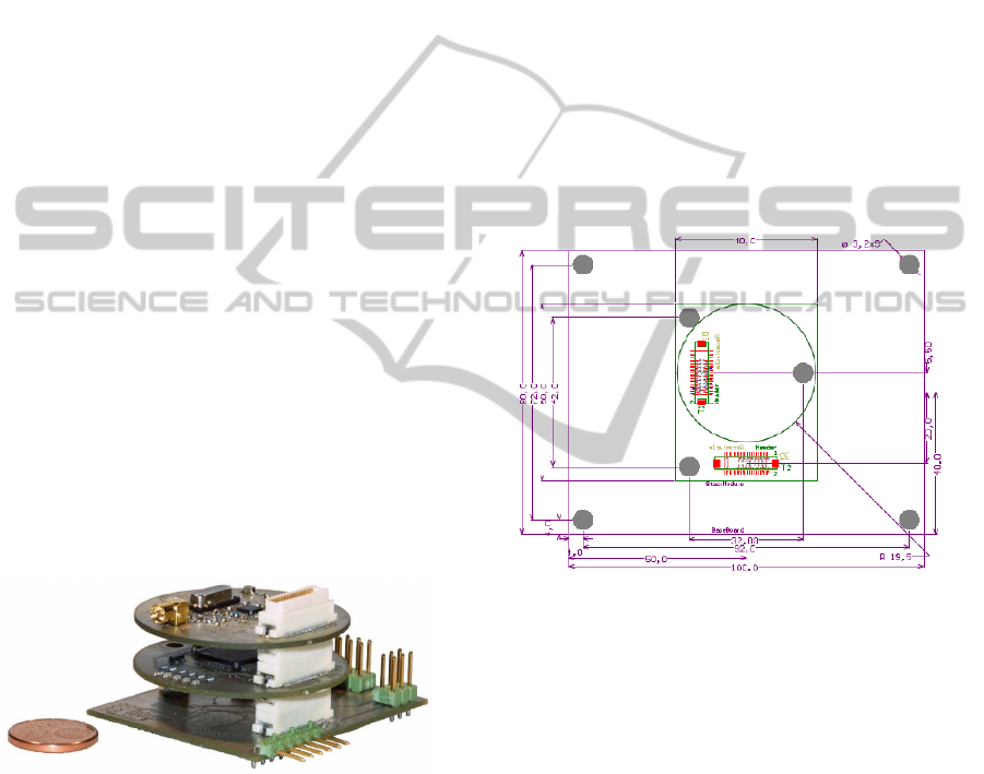
tions. Figure 1 shows the TandemStack development
stack with a power supply and debugging module, a
processing module as well as a radio module.
Figure 1: TandemStack development board with a power
and debugging bottom module, a MSP430-based process-
ing and a radio stack module in comparison with an one
cent coin.
3.1 Configuration and Design
Restrictions
In order to achieve interoperability between the mod-
ules the design of a module must follow certain con-
figuration premises. We defined restrictions for the
connector’s pinning, routing and placement as well as
a minimum of required features on a module.
Although Figure 2 shows a recommended outline,
this is not a restriction. We think a predefined board
dimension will reduce mote’s flexibility in a signifi-
cant manner. A designer should have the freedom to
adapt the node to the application requirements instead
of outline restrictions. However, for the sake of in-
teroperability modules must follow predefined place-
ments and pinning for the board-to-board connectors
and position of mounting holes. On a stack module all
header and receptacle pins must be connected (an ex-
ception are user defined pins and uni-directional pins
like the JTAG chain). Furthermore the height of top
side components is limited to 6mm and on the bottom
side it is limited to 1.8mm. These limits are necessary
to ensure that all modules can be plugged together.
On top modules the top side height and on bottom
modules the bottom side height of components is not
restricted.
Figure 2: Dimension and placement of holes for the three
different modules formats. Boards are dimensioned from
the centre. Origin is the lower left corner.
Every TandemStack must have a bottom layer
module. It has to source 3.3V and 5.0V supply. Fur-
thermore, pullup resistors for e.g. I
2
C and reset lines
have to be placed on a bottom module. Stack and
top modules must not source 3.3V and 5.0V, but may
source an additional raw voltage. This way it is i.e.
possible to build a solar panel power supply as a top
module.
External connectors that provide communication
interfaces to the stack should be placed on the bottom
module. Buttons may also be placed there. Although
top modules are a possible place for buttons and ex-
ternal connectors too, the bottom module should be
preferred, because a bottom module is required in a
stack configuration, while a top module is optional.
TandemStack - A Flexible and Customizable Sensor Node Platform for Low Power Applications
67

Table 1: List of already implemented TandemStack modules.
Class Type Device Dimension Connectors
Power Supply Bottom Thermo Electric Generator (TEG) ∅ 40mm X1
Power Supply Bottom Battery supply ∅ 40mm X1
Power Supply Bottom USB supply 40mm x 50mm X1, X2
MCU Stack MSP430F161x ∅ 40mm X1
MCU Stack MSP430F5438A 40mm x 50mm X1, X2
MCU Stack Sparc V8 based LEON-2 40mm x 50mm X1, X2
Transceiver Stack 868MHz CC1101 radio ∅ 40mm X1
Transceiver Stack 868MHz CC1190 amplifier ∅ 40mm X1
Transceiver Top Bluetooth Blue-SP ∅ 40mm X1
3.2 Mote Component
Interconnect (MCI)
In contrast to other configurable motes the Tandem-
Stack uses a strictly defined Mote Component In-
terconnect (MCI). That means each module must
place its board-to-board connectors on defined posi-
tions and must use a predefined pinning. Our MCI
supports a number of common mote interfaces such
as GPIOs, buses, interrupt and analog lines as well as
a common programming interface.
As mentioned before one MCI connector is op-
tional (X2) and one is compulsory (X1). The op-
tional connector X2 will be used only on layers with
a larger footprint. Table 2 shows the defined pining
of connector X1. Connector X1 includes all com-
mon peripheral interfaces of a typical mote. Connec-
tor X2 is an extension of X1 and provides more ana-
log, GPIO, event, power and user definable lines. Fur-
thermore, for specialized applications two additional
power lines Vraw1 and Vraw2 and four counter lines
are available on connector X2.
We use two 50-pin connectors from Hirose, which
make a high-density of components possible. It has
a 0.5 mm pitch and is available in a range of heights
from 5 to 8mm, which allows a tailoring of the board-
to-board gap for a better matching of a required stack
height. Its high pin density enables the use of highly
integrated MCUs while maintaining a good mechani-
cal stability and ruggedness.
3.2.1 Signal Routing
For a free ordering of stack modules all common MCI
pins must be routed between bottom and top board-
to-board connector. It is permitted to route pins via
a module’s Integrated Circuit (IC), where an IC must
be active forwarder between both connectors. We call
this configuration an active routing. In a passive rout-
ing configuration an IC is only connected to a static
line between both connectors. Furthermore, an ac-
Table 2: Pining of 50-pin MCI connector X1. The connec-
tor must be available on all layers and has s strictly defined
pinning with all common mote peripheral interfaces.
Pin Name Type Pin Name Type
1 5V0 Power 26 GPIO1 GPIO
2 5V0 Power 27 GPIO2 GPIO
3 3V3 Power 28 GPIO3 GPIO
4 3V3 Power 29 GPIO4 GPIO
5 GND Power 30 GPIO5 GPIO
6 TEST JTAG 31 GPIO6 GPIO
7 TCK JTAG 32 GPIO7 GPIO
8 TMS JTAG 33 AD0 Analog
9 TDO JTAG 34 AD1 Analog
10 TDI JTAG 35 AD2 Analog
11 Reset Reset 36 AD3 Analog
12 MCLK Clock 37 IRQ0 Event
13 MISO SPI 30 IRQ1 Event
14 MOSI SPI 31 IRQ2 Event
15 CLK SPI 32 IRQ3 Event
16 CS SPI 41 UDEF0 Udef
17 RX UART 42 UDEF1 Udef
18 TX UART 43 UDEF2 Udef
19 SCL I2C 44 UDEF3 Udef
20 SDA I2C 45 UDEF4 Udef
21 D+ USB 46 UDEF5 Udef
22 D- USB 47 UDEF6 Udef
23 GND Power 48 UDEF7 Udef
24 GND Power 49 GND Power
25 GPIO0 GPIO 50 GND Power
tive routing makes a bus interruption or an isolation
of stack modules feasible. Interrupting buses may be
useful to operate with peripheral devices with differ-
ent bus parameters, e.g. clock speed or data width.
While using passive routing all components share a
bus and must operate with same parameters as well
as all bus members can see and influence transmitted
data. For safety, dependability and security aspects an
isolation of components can be useful. An active rout-
ing configuration is also useful to connect a plurality
SENSORNETS 2012 - International Conference on Sensor Networks
68

of components to a peer-to-peer link, like UART or
USB.
3.2.2 Signal Types
We classified the signals used on motes in 13 differ-
ent types. Most of these types are supported by all
commercially available MCUs. Classifying mote sig-
nals will improve the module’s interoperability. In the
following we will introduce all 13 types in detail.
Power is used for a module’s power supply. It
includes 5.0V, 3.3V and ground lines. The Hirose
board-to-board connector limits the current on single
pins to 300mA. For supporting higher current mod-
ules a multiple number of power pins are defined. In
addition to the basic supply voltage two Vraw lines
are defined. These lines can be used with a user spe-
cific voltage.
GPIO lines are general digital input/output lines
with no special properties other than being able to ac-
cept 5V even when operating on 3.3V. This restriction
is true for any non-power signal.
USB lines can be used to connect ICs and/or ex-
ternal connectors via USB. Although USB requires
a point-to-point connection and only one component
can be connected to the lines D+ and D-, a USB net-
work can be deployed over a TandemStack by using
USB hubs, as shown in Figure 3. USB is strictly dif-
ferenced in master and slave, so that or a free module
ordering a slave must be connected to the bottom side
receptacle and a master to the top side header.
DEVICE
HUB
bottom
top
Figure 3: Routing of USB lines on a stack module by using
a hub in an active routing configuration.
Event lines are a special type of GPIO lines.
These lines are connected to IC pins with interrupt
support for asynchronous event handling. It can also
be used as a digital GPIO, if the available number of
GPIOs is not sufficient.
Analog lines are GPIO lines, which are connected
to an A/D converter input. In contrast to GPIO lines
the signal level of analog lines is not defined and can
be any value between zero and one of the stack’s sup-
ply voltage. A use as GPIO line is not recommended
to ensure compatibility.
Clock line can be used to deploy an IC clock over
a multiple number of modules. The line is driven by
a single module, normally the MCU module, and can
be used by a multiple number of ICs with external
clock input.
Reset line is used as a low active system reset.
The signal is fed to all modules and can be used to
synchronize stack ICs. A reset network can be built
up by using active routing.
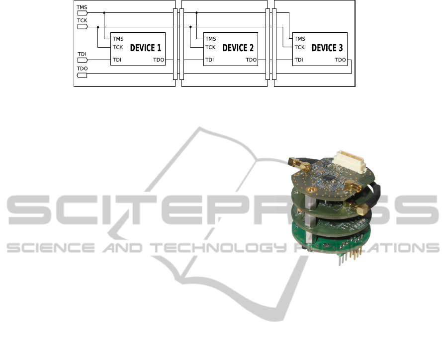
JTAG is the stack programming interface. It sup-
ports device chaining, which makes the number of re-
quired lines independent from the number of devices.
Figure 4 shows the Joint Test Action Group (JTAG)
chain in the TandemStack. An external connector
must be placed on the bottom module. On each stack
module the Test Data In (TDI) bottom connector pin
is connected with the IC’s TDI, while its Test Data
Out (TDO) is forwarded to the top connector. On a
top module the JTAG chain must be closed by con-
necting IC’s TDO with the bottom connector TDO
pin. By the fact that a top module is optional each
stack module may have a configurable short.
UDef can be used for coupling two familiar mod-
ules. Although a strict limitation for the module’s di-
mension is not given a module may need more than
one layer to assemble all required components. In this
case a module can be easily spread over more than
one layer by using the user defined pins. The MCI in-
cludes 16 user defined lines without pre-defined use.
Only devices, which use these pins may connect to
them. The pins must be routed between both connec-
tors and the IC. But the devices must be placed as
adjacent devices, while a routing of UDEF pins is not
permitted on layers that do not use it.
SPI, as most common bus interface for low power
motes, is a synchronous serial data link operating in
full duplex mode. Devices will be differenced in a
master and a multiple number of slaves. Slaves are
addressed with individual select lines. The MCI de-
fines three data lines and one select line. Additional
slave could be addressed by a GPIO line. In an ac-
tive routing configuration a slave must be connected
to the bottom side connector and a master to the top
side connector. By using a passive routing a module
can be a slave as well as a master.
I
2
C is another synchronous serial data link. In
contrast to Serial Peripheral Interface (SPI) I
2
C uses
only two lines, a data and a clock line, and is multi-
master capable. These properties significantly sim-
plify routing, but require a more complex driver soft-
ware. Like all multi-master buses I
2
C requires exter-
nal pullup resistors for both lines. On a TandemStack
these resistors are placed on a bottom module or in
case of an active routing on the bus-breaking module.
TandemStack - A Flexible and Customizable Sensor Node Platform for Low Power Applications
69
Bottom Layer
Stack Layer
Top Layer
Figure 4: TandemStack JTAG chain. Devices are chained by connecting TDO with TDI between neighbored devices. The
chain must be closed by a top layer module. TMS and TCK are connected to all devices.
UART is a type of asynchronous re-
ceiver/transmitter. It requires at least two lines,
RX and TX, but is not a bus with a multiple number
of peers. An UART link is a strict point-to-point
connection with two peers. Due to this limitation
the TandemStack supports in a passive routing
configuration only one UART between the modules.
For a multiple number of links an active routing must
be implemented.
Counter lines are only available on the connector
X2 and can be used as a counter input to accurately
measure event timing or frequencies.
4 APPLICATION SCENARIOS
Typical application fields for motes are very wide
and rapidly growing. They include sensing environ-
mental parameters, controlling or monitoring indus-
trial plants, buildings as well as public infrastructures.
Below we describe three current examples for our
TandemStack.
4.1 Low Power IEEE 802.15.4 Mesh
Network
In the IQlevel project a network of observation wells
for measuring the groundwater level in a drainage
area should be digitalized. As main project objec-
tive IQlevel mote must operated without a permanent
power supply and must be integrated in a 2-inch ob-
servation pipe. The distance among the nodes differs
from 100 up to 1.500meters and the territory changes
from free field with a line of sight to forests with heav-
ily obstructed connections. Due to these requirements
and broad variation in the transmission range a flexi-
ble mote design was needed. Figure 5 shows the re-
sulting round mote design with at least three layers
and an optional CC1190 amplifier module. Besides
a battery, power supply can also be supplemented by
a alternative TEG module. To reduce material costs
amplifiers and TEG will only be deployed with a node
when its is needed.
Figure 5: IQlevel mote with battery power supply, MCU,
868MHz transceiver and amplifier module.
4.2 Research and Development
Although the basic ideas of our TandemStack were
driven by the IQlevel project we realized during the
project time that our TandemStack is also very help-
ful for testing new ICs. At the IHP various research
groups are working on highly efficient mote com-
ponents. Testing these devices requires a platform
where single components can be replaced easily. Our
TandemStack approach fulfills all these requirements
better than the state of the art.
With our TandemStack topology it is possible to
test new MCUs or radio baseband processors by de-
signing a single PCB. Furthermore we can compare
our devices with commercially available ones by run-
ning similar software on the devices under test. The
adaptable TandemStack platform makes hardware de-
velopment processes more structured and efficient
and therefore more cost effective.
4.3 WSN Bridge
Low power WSNs are the main use case of IEEE
802.15.4 based radio modules. But IEEE 802.15.4
low power and mesh network capabilities make a con-
nection to standard infrastructuresmore tricky and de-
vices are rare as well as expensive. In the context of
SENSORNETS 2012 - International Conference on Sensor Networks
70

the Trusted Sensor Node (TSN) project we design a
mote with an IEEE 802.15.4 and a bluetooth inter-
face. As illustrated in figure 6, by using a TSN device
a low power WSN can be connected to any bluetooth-
capable device, e.g. a simple handheld device. The
TSN uses an IPv4 protocol stack via its bluetooth in-
terface to external devices, so that integration in stan-
dard infrastructures is quite simple.
IEEE 802.15.4 sensor network
Bridge Mote
Figure 6: TSN mote as sink of a WSN, which is
equipped with two different transceivers and bridges an
IEEE 802.15.4 sensor network with a bluetooth handheld
device.
For running complex protocol stacks the TSN
mote should be equipped with a powerful 32-bit pro-
cessor. We chose a LEON-2 core, which was fabri-
cated in the IHP in house fabrication plant (fab). Be-
sides the LEON-2 core was extended with hardware
accelerators for cryptographic methods. For the blue-
tooth and IEEE 802.15.4 interface standard devices
were used. If motes and TSN are implemented as
TandemStack motes almost all layers can be reused.
5 MOTE’S COMPARISON
One important factor for the comparison of motes is
their respective processing power. Especially in large
scale nets with star topologies, the processing power
for data sinks and bridge nodes can become a bottle-
neck for network performance, whereas in small scale
networks this might be a waste of resources. Most
mote designs have a fixed CPU that dictates its pro-
cessing power. Consequently, the network’s ability
and structure are chosen to fit the node’s abilities, not
vice versa. IHP TandemStack solves this problem as
single node’s processing power can be suited to the
network structure and can be designed to be optimal
for the given challenge. For example if a star network
is desired, the center node can be as powerful as the
throughput demands and the single motes can imple-
ment a low-performance CPU.
Besides processing power, electrical and physical
characteristics are important values for mote’s usabil-
ity. We compared powerconsumption and footprint of
our TandemStack mote to five commercially available
motes. The results are summarized in table 3. The
TandemStack was built up with an MSP430-based
MCU module, an 868MHz radio module and was di-
rectly powered by 3.3V without DC/DC converter.
We can see that the smallest footprints are achieved
by stacked designs. The additional mote’s height is an
acceptable factor as most applications have a minimal
height, which allows packaging of two or three layers.
Furthermore, in comparison with a TmoteSky, we see
that a stacked design with its additional connectors
has a few µWatts higher idle consumption only.
Table 3: Comparison of mote’s footprint and power con-
sumption.
Mote Idle Footprint
TandemStack 29.7 µW 40x40 mm
IHPNode 8.4 mW 50x70 mm
TmoteSky 15.3 µW 32x66 mm
Mica2 75 µW 58x32 mm
Tyndall25 60 mW 25x25 mm
JN5148 12.4 µW 30x45 mm
Another crucial point for motes abilities is their
RF interface. Whereas most of them implement a
single radio or a number of radios to choose from,
our TandemStack can implement virtually any radio
on the market. This holds true not only in single
path communications, but also in multi-path designs.
Furthermore, our open interface opens the opportu-
nity to implement nodes that are not limited to ISM-
band communication only. Very specialized applica-
tions such as 403MHz medical implants, astronomi-
cal bands or even non-public bands and bridge appli-
cations between protocols and standards can be im-
plemented.
The IHP approach therefore also solves the prob-
lem of local radio permission authorities. Most motes
are limited to worldwide ISM-bands to give them the
minimum common intersection set between standards
worldwide. This leads to an increasing load of these
few international frequencies, which makes it harder
to set up a local network with standard equipment.
On the other hand there are readily available radios
in most countries that fit in local standards and serve
bands that are usually not as heavily packed as inter-
national frequencies. The ability of the TandemStack
to meet international standards as well as to inherently
serve special demands of any given application makes
it one of the most versatile mote solutions so far.
Compared to other standard sensor nodes, the
TandemStack can be advantageous in space-limited
applications while still maintaining the highest level
of flexibility. Whereas the design of other motes is
restricted, the modular IHP approach allows designer
TandemStack - A Flexible and Customizable Sensor Node Platform for Low Power Applications
71

to start developing application on a comfortably sized
development environment. At same time, as soon
as application is specified, it is possible to develop
a shrunk application platform, which uses previously
designed and tested software. This work flow ensures
highest level of flexibility and saves a lot of precious
development time.
6 FUTURE WORK
The interoperability of modules is tightly coupled
with a careful assignment of GPIOs. For example a
multiple use of GPIO lines must be avoided as any
SPI slave needs a dedicated chip select or interrupt
line. Our current set of TandemStack modules is still
surveyable. To keep an overview becomes more and
more difficult with future extensions. A tool support
will significantly simplify such a planning process.
Such a tool can help to find a suitable combination of
modules or selection of lines for upcoming modules.
Driven by active projects a broad set of stack mod-
ules is already implemented. Nonetheless, some mod-
ules, which are very useful in research and typically
WSN scenarios, are still missing. Next steps will in-
clude the design of a storage or an FPGA module.
In a lot of application scenarios a low power stor-
age module with a capacity in the megabytes range
will be needed. Flash memories with SPI or I
2
C are
available and fit perfectly to our TandemStack. Fur-
thermore, an FPGA as a high performance, reconfig-
urable processing core is therefore very useful for de-
velopment or required for massive data processing,
e.g. video stream encoding. It can be implemented as
an MCU replacement as well as a high performance
co-processing unit.
7 CONCLUSIONS
This paper described the TandemStack platform and
its Mote Component Interconnect (MCI). The
TandemStack follows the objective to assemble as
few components as possible needed for one functional
unit on a single Printed Circuit Board (PCB). We
assume that modules should only include one mote
component such as MCU, transceiver, power supply,
storage or sensor. Later the modules are connected
by a uniform MCI. We have explained how such
an interconnect can be defined for building a flexi-
ble mote platform where modules can be freely com-
bined. We compared our design with commercially
available motes and demonstrated that a stack archi-
tecture will provide the highest component density.
We illustrated that in contrast to the inflexible motes
our design can be used in various application scenar-
ios with minimal development effort. We have al-
ready implemented more than nine different modules
and could gather experimental results in real world
scenarios as well as in research activities. We are cer-
tain that a flexible, standardized mote platform can
significantly push development activities and mote
deployments.
REFERENCES
Bellis, S. J., Delaney, K., O’Flynn, B., Barton, J., Razeeb,
K. M., and O’Mathuna, C. (2005). Development of
field programmable modular wireless sensor network
nodes for ambient systems. Comput. Commun., 28.
Benbasat, A. Y. and Paradiso, J. A. (2005). A compact
modular wireless sensor platform. In Proceedings of
the 4th international symposium on Information pro-
cessing in sensor networks, IPSN ’05, Piscataway, NJ,
USA. IEEE Press.
Coalesenses (2011). iSense Wireless Sensor Network Hard-
ware Modules.
Crossbow (2011). Moog Crossbow Technologies.
Dutta, P., Taneja, J., Jeong, J., Jiang, X., and Culler, D.
(2008). A building block approach to sensornet sys-
tems. In Proceedings of the 6th ACM conference on
Embedded network sensor systems, SenSys ’08, pages
267–280, New York, NY, USA. ACM.
Evidence (2010). Technical datasheet - Flex mini kit.
Horton, M., Culler, D., Pister, K., Hill, J., Szewczyk, R.,
and Woo, A. (2002). MICA, the commercialization of
microsensor motes. Sensors, 19(4):40–48.
Labs, S. (2010). Sun SPOT Main Board Technical
Datasheet.
Lymberopoulos, D., Priyantha, N. B., and Zhao, F. (2007).
mPlatform: a reconfigurable architecture and efficient
data sharing mechanism for modular sensor nodes. In
Proceedings of the 6th international conference on In-
formation processing in sensor networks, IPSN ’07,
pages 128–137, New York, NY, USA. ACM.
Moteiv (2006). Tmote Sky Datasheet
http://www.sentilla.com/pdf/eol/tmote-sky-datasheet.
pdf.
Piotrowski, K., Sojka, A., and Langend¨orfer, P. (2010).
Body Area Network for First Responders - a Case
Study. In Proceedings of the 5th International Con-
ference on Body Area Networks.
Polastre, J., Szewczyk, R., and Culler, D. (2005). Telos:
enabling ultra-low power wireless research. In Infor-
mation Processing in Sensor Networks, 2005. IPSN
2005. Fourth International Symposium on, pages 364
– 369.
Schott, B., Bajura, M., Czarnaski, J., Flidr, J., Tho, T., and
Wang, L. (2005). A modular power-aware microsen-
sor with 1000x dynamic power range. In Proceed-
ings of the 4th international symposium on Informa-
tion processing in sensor networks, IPSN ’05, Piscat-
away, NJ, USA. IEEE Press.
SENSORNETS 2012 - International Conference on Sensor Networks
72
