
SHAPE REPRESENTATION AND A MORPHING SCHEME TO
SUPPORT FLAPPING WING RESEARCH
Mohammad Sharif Khan and Tapabrata Ray
School of Engineering and Information Technology, University of New South Wales, Canberra 2610, Australia
Keywords:
Flapping wing, Shape representation, Shape matching.
Abstract:
Wing geometry is one of the most important factors that affects the performance of a flapping wing. The
shape of insect wings and their nature of flapping varies across insect species. In order to gain an in-depth
understanding of flapping flight with an aim to identify optimal wing shapes, there is a need for an universal
and flexible shape representation scheme that is amenable to optimization. The paper presents a methodology
to represent boundaries of insect wings which can be subsequently morphed via an optimization algorithm.
The shapes are represented using B-splines, wherein the control points representing the shapes are repaired
and subsequently evolved within an optimization framework. Twelve insect-wing shapes have been used to
test the performance of the proposed method in the context of shape matching.
1 BACKGROUND
Research into flapping wings have gained significant
attention in the last two decades (Donoughe et al.,
2011; Nguyen et al., 2010). The wing area, wing
span, aspect ratio, stiffness and flapping frequency are
factors that are known to greatly influence the perfor-
mance in terms of thrust and lift generation (Brugge-
man, 2010).
In the context of flapping wing research, most
of the papers attempt to study the effects of kine-
matics. There are only a small number of papers
that have considered wing shapes (Altshuler et al.,
2004; Phillips et al., 2010; Yuan et al., 2010; Ou
and Jameson, 2011; Ou et al., 2011). An analy-
sis of aerodynamic forces of revolving hummingbird
wings and wing models is reported in (Altshuler et al.,
2004), wherein the planform of the wing model was
based on image of the left wing of a female ruby-
throated hummingbird (Archilochus colubris) with a
wing length of 46.5 mm and an aspect ratio of 7.72.
An experimental investigation of the effects of plan-
form on the flow structures generated by an insect-
like flapping wing in hover is presented in (Phillips
et al., 2010). Four planform shapes with a constant
area and aspect ratio of approximately 6 were con-
sidered: reverse-ellipse, rectangle, four-ellipse and
ellipse. Numerical simulations were performed in
(Yuan et al., 2010) for a symmetrical NACA0005 air-
foil in combined pitching-plunging motions at low
Reynolds numbers. Three-dimensional simulations
of the two-dimensional airfoils with rectangular plan-
form have been carried out with an Eppler61 air-
foil and an oscillating NACA0012 airfoil at Reynolds
number 46,000 and 40,000 respectively in (Ou and
Jameson, 2011).
It is interesting to observe that in the field of flap-
ping wing research, there is a move towards modeling
insect like wing planforms with an aim to understand
their effects on propulsive characteristics. The work
outlined in this paper aims to provide a mechanism to
represent and optimize wing shapes in order to un-
derstand the effects of wing shapes on the propul-
sive characteristics of a flapping flight. To this effect,
we developed a flexible shape representation scheme.
The flexible shape representation scheme when cou-
pled with an optimization algorithm forms an useful
tool that can be used to understand and answer why
certain wing shapes have evolved within certain class
of insects. It is important to highlight that both the
efficiency of the optimization algorithm and the flex-
ibility of shape representation scheme require serious
attention. A lack of flexibility in shape representation
will limit the evolution of various shapes, while an
inefficient optimization algorithm will require evalua-
tion of numerous shapes prior to its convergence, both
of which are not desirable (Khan et al., 2011).
The boundary of a shape (such as a wing) can be
represented using one of the following schemes: im-
plicit polynomials (Landa et al., 2010), active con-
494
Khan M. and Ray T. (2012).
SHAPE REPRESENTATION AND A MORPHING SCHEME TO SUPPORT FLAPPING WING RESEARCH.
In Proceedings of the 1st International Conference on Pattern Recognition Applications and Methods, pages 494-499
DOI: 10.5220/0003840304940499
Copyright
c
SciTePress
tours (Xu and Prince, 1998), cubic splines (Rogers
and Adams, 1990), Bezier curves (Rogers and
Adams, 1990) and B-spline curves (Cox, 1971;
Riesenfeld, 1972). Among the above listed repre-
sentations, B-spline curves have been most widely
used as it ensures smoothness, compactness, local
shape control, and affine transformation invariance
(Mongkolnama et al., 2006). A B-spline representa-
tion has been used in the present study wherein the
control points of the curve are identified through an
optimization algorithm. A novel repair scheme is in-
troduced and embedded to ensure generation of valid
shapes (one without self intersection). The non-global
behavior of B-spline curves makes it attractive in the
realm of shape representation. The B-spline basis
also allows the order of the basis function and hence
the degree of the resulting curve to be changed with-
out changing the number of defining polygon vertices
(Rogers and Adams, 1990). Another advantage of the
B-spline curve is its strong convex-hull property. It
also possesses the variation diminishing and affine in-
variance properties.
In the context of shape matching, the aim is to
identify a shape that is similar to a target shape.
While methods based on active contours are com-
monly used in the field of pattern recognition (Xu and
Prince, 1998), it must be highlighted that such meth-
ods use local information to update location of the
points representing its boundary and hence not suit-
able for black-box optimization problems. In the cur-
rent black-box application however, a single scalar er-
ror value (matching error) is only available to direct
the search. In the present study, we assume that the
length and the width of a common box enclosing all
insect wings are known.
Rest of the paper is organized as follows. The
method proposed in this paper is presented in Sec-
tion 2. The results are reported in Section 3. Finally,
some concluding remarks are provided in Section 4.
2 PROPOSED METHOD
In the proposed method, the number of control points
required to represent the shape, the dimensions of the
box enclosing the target shape and the centroid of the
target shape are assumed to be known. The variables
of the optimization problem are the x and y coordi-
nates of the control points, the range of which are
the same as the dimensions of the enclosing box. Ev-
ery solution generated through the process of initial-
ization or recombination is repaired, wherein the se-
quence of control points are changed to obtain a non-
intersecting polygon net while maintaining the spe-
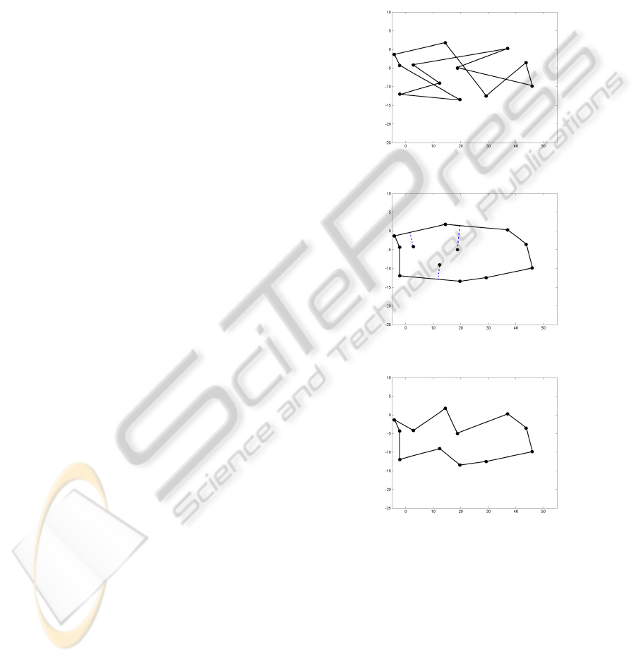
cific values of its coordinates. The concept is illus-
trated using Figure 1, 2 and 3, where the original ran-
domly generated control polygon net and formation
of the convex-hullare presented alongside its repaired
form. Firstly, a convex-hull is generated using a set of
control points (Figure 2). Thereafter, the points (lying
inside the convex-hull) nearest to their adjacent edges
are inserted to generate the non-intersecting control
polygon net (Figure 3).
1
2
3
4
5
6
7
8
9
10
11
12
Figure 1: Position of initial control points without repair.
1
2
12
8
6
7
4
5
9
10
11
3
Figure 2: Convex-hull formation with initial control points.
1
2
12
8
6
7
4
5
9
3
10
11
Figure 3: Position of initial control points after repair.
2.1 Initialization and Repair Strategy
The number of control points (N) used to describe a
shape is a user defined parameter. Since the limits
of x and y coordinates i.e. the space enclosing the
target shape is known, a random solution is created
and repaired during the phase of initialization.
2.2 Matching Error
Since the centroid of the target shape is known, the
SHAPE REPRESENTATION AND A MORPHING SCHEME TO SUPPORT FLAPPING WING RESEARCH
495

shape generated using the repaired solution (re-
ordered set of control points) is shifted such that its
centroid matches the centroid of the target shape.
The maximum of Euclidean and Hausdorff distance
is computed using the generated shape and the target
shape.
2.3 Optimization Algorithm
2.3.1 Evolution
The pseudo-code of the proposed optimization is pre-
sented in Algorithm 1 and 2. In the proposed algo-
rithm, two different evolution strategies are used for
generating the offspring population. These are:
Algorithm 1: Proposed algorithm.
1: pop
1
= Initialize {Assumption of number of con-
trol points}
2: pop
1
= Repair (pop
1
) {Maintaining the sequence
of control points considered as variables}
3: CP
n
= Centroid Shift (s
T
, s
G
) {Shifting of con-
trol points towards a particular distance measured
with the difference between the centroids of tar-
get and generated shapes}
4: E dist = Max (Eucli dists (s
T
, s
G
))
5: H dist = Hausdorff dist (s
T
, s
G
)
6: Matching Error = Max (E dist, H dist)
7: Hybrid Memetic Algorithm presented in Algo-
rithm 2
1. EA-like evolution – This includes simulated bi-
nary (SBX) crossover and polynomial mutation
(Deb and Agarwal, 1995).
2. DE-like evolution – This includes the DE expo-
nential crossover and mutation, as described in
(Das and Suganthan, 2010).
2.3.2 Ranking and Reduction
Since the test problems studied in the paper are for-
mulated as single-objective, unconstrained minimiza-
tion problems, the ranking is done by sorting the ob-
jective values in ascending order. The best N so-
lutions from the (parent+child) population form the
population for the next generation.
2.3.3 Local Search
At each generation, in addition to generation of new
solutions using recombination and mutation, a local
search is used for further improvement. Sequential
quadratic programming (SQP) (Powell, 1978) is used
for the local search in the present study. After perfor-
Algorithm 2: Hybrid memetic algorithm.
Require: Population size (N), Number of genera-
tions (N
G
), Crossover and mutation parameters.
1: pop
1
= Initialize
2: pop
1
= Repair (pop
1
)
3: Evaluate (pop
1
)
4: for i = 2 to N
G
do
5: if rand (0,1) ≤ 0.5 then
6: childpop
i
= Evolve EA (pop
i−1
)
7: else
8: childpop
i
= Evolve DE (pop
i−1
)
9: end if
10: childpop
i
= Repair (children
i
)
11: Evaluate (childpop
i
)
12: S = Rank (pop
i−1
+ childpop
i
)
13: if rand (0,1) ≤ 0.2 then
14: x = Random x ∈ pop
i
{Select a random so-
lution}
15: else
16: x = Choose start x (pop
i
) {Select a solution
as described in Section 2}
17: end if
18: x
best
← Local search (x) {x
best
is the best so-
lution found using local search from x}
19: Replace worst solution in pop
i
with x
best
20: pop
i
= Rank(pop
i
) {Rank the solutions again
in pop
i
}
21: if local search doesn’t improve the objective
value for K consecutive generations then
22: pop
i
= Re-initialize () {Retain the best solu-
tion while re-initializing}
23: pop
i
= Repair (pop
i
)
24: end if
25: end for
ming the local search, the worst solution in the popu-
lation is replaced by the best solution found from the
local search.
2.3.4 Re-initialization
In order to prevent the algorithm from stagnating at a
local optima, the population is reinitialized if there is
no improvement observed in the objective value for
more than K (=10) generations. The best solution
found during the search is preserved in the population
during re-initialization.
3 RESULTS
The boundaries of the wings are extracted digitally
and then target shapes are obtained via direct inverse
ICPRAM 2012 - International Conference on Pattern Recognition Applications and Methods
496

Table 2: Matching error between target and generated dragonfly-wing shapes.
Dragonfly wing wing-1 wing-2 wing-3 wing-4 wing-5 wing-6 wing-7
Matching error (proposed method) 6.4e-05 1.8e-05 1.9e-04 2.3e-05 3.8e-05 7.1e-05 2.2e-05
Matching error (real-coded EA) 4.019 3.670 2.747 3.850 5.071 5.388 3.854
Table 3: Matching error between target and generated damselfly-wing shapes.
Damselfly wing wing-1 wing-2 wing-3 wing-4 wing-5
Matching error (proposed method) 2.1e-04 2.9e-05 7.1e-04 0.9e-05 3.3e-05
Matching error (real-coded EA) 3.466 5.849 4.545 3.833 2.562
Table 4: Results of multiple runs for dragonfly-wing and damselfly-wing shapes using proposed method.
Shapes Error Measurement Best Worst Mean Median Std.
Dragonfly-wing-1 Max(Eucli,HD) 0.7e-05 1.57e-04 5.0e-05 3.3e-05 4.0e-05
Dragonfly-wing-5 Max(Eucli,HD) 0.9e-05 2.11e-04 5.2e-05 1.8e-05 6.9e-05
Damselfly-wing-2 Max(Eucli,HD) 0.8e-05 3.3e-04 6.2e-05 2.7e-05 8.9e-05
Damselfly-wing-5 Max(Eucli,HD) 0.7e-05 1.73e-04 4.0e-05 2.9e-05 3.6e-05
Table 5: Results of multiple runs for dragonfly-wing and damselfly-wing shapes using real-coded Evolutionary Algorithm.
Shapes Error Measurement Best Worst Mean Median Std.
Dragonfly-wing-1 Max(Eucli,HD) 1.763 8.796 4.894 4.395 1.823
Dragonfly-wing-5 Max(Eucli,HD) 2.813 8.085 4.663 4.034 1.686
Damselfly-wing-2 Max(Eucli,HD) 3.540 6.402 5.097 5.344 0.815
Damselfly-wing-5 Max(Eucli,HD) 2.219 6.255 3.719 3.453 1.066
Table 1: Parameters used for the proposed algorithm.
Parameter Value
Population size 40
Max. function evaluations 10000
Crossover probability 1.0
Crossover index 10
Mutation probability 0.05
Mutation index (polynomial) 20
Scale factor F (for DE mutation) 0.9
fitting in order to remove noise from their bound-
aries (Figure 4). Seven dragonfly-wing shapes and
five damselfly-wing shapes are used to test the per-
formance of the proposed approach. Dragonfly-wing
shapes contain 493 to 525 points while Damselfly-
wing shapes contain 491 to 516 points. The param-
eters used for the algorithms are the same for each
shape matching exercise, i.e., no tuning of parameters
is done across the problems. The parameters are listed
in Table 1. A maximum of 10000 function evaluations
are set for each problems.
For all the problems, we have assumed they can be
represented using 20 control points which translates
to a 40 variable optimization problem. A common
box has been chosen as the search domain represent-
ing between 0 to 58 in the x direction and between
0 to 17 in the y direction for all the problems. The
results after 10000 function evaluations for dragonfly-
wing and damselfly-wing shapes are shown in Table 2
and Table 3 respectively. For the sake of comparison,
the results of using a real-coded evolutionary algo-
rithm are also presented alongside the results of the
proposed method.
The statistics of the multiple runs of some exam-
ples are presented in Table 4, which reflects the con-
sistency of the proposed approach. The best and worst
values are reported as the minimum and maximum er-
rors across 20 runs, respectively. The median value
reported is the average of 10
th
and 11
th
values in the
sorted list of matching errors obtained across 20 runs.
The matching errors for all the examples are fairly low
in the order of 1e
−
05. In an attempt to observe the
performance of the proposed method, the results of
the multiple runs of using a real-coded evolutionary
algorithm are also presented in Table 5. It is clear
from Table 4 and Table 5, that a significant improve-
ment in performance has been achieved through the
SHAPE REPRESENTATION AND A MORPHING SCHEME TO SUPPORT FLAPPING WING RESEARCH
497
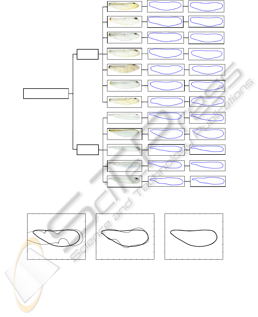
A. constricta
S. vicinum
E. simplicicolis
47 mm
E. cynosura
25 mm
32 mm
29 mm
A. verticalis
52 mm
S. rubicundulum 26 mm
S. tenebrosa
37 mm
I. posita
C. angustipennis
E. divagans
I. vertcalis
L. rectangularis
17 mm
40 mm
21 mm
15 mm
22 mm
Species Wing length
Epiprocta
(dragonflies)
Zygoptera
(damselflies)
Odonata
(dragonflies and damselflies)
A
B
C
Figure 4: A: Dragonfly and damselfly wing species with their length (Donoughe et al., 2011). B: Original shapes’ boundaries
(digitized) of wing species. C: Shapes’ boundaries are represented via direct inverse fitting.
−5 0 5 10 15 20 25 30 35 40 45
−20
−15
−10
−5
0
5
10
−5 0 5 10 15 20 25 30 35 40 45
−20
−15
−10
−5
0
5
10
−5 0 5 10 15 20 25 30 35 40 45
−20
−15
−10
−5
0
5
10
Figure 5: Evolutions of generated damselfly-wing-2 (thin) towards the target damselfly-wing-2 (thick) for matching.
use of the proposed method across all the problems.
Various states of evolutions (from 1 to 10000 func-
tion evaluations in 3000 interval) of generated shape
towards the target or original shape are shown in Fig-
ure 5 for damselfly-wing-2 example.
4 DISCUSSION AND
CONCLUSIONS
There is an increasing interest to understand flapping
behavior of insect wings with an aim to identify effi-
cient propulsive mechanisms for micro air vehicles.
While flapping wing kinematics have been the pri-
mary focus for the last decade, there are increasing
number of attempts in recent years that tend to model
ICPRAM 2012 - International Conference on Pattern Recognition Applications and Methods
498

insect like wing planforms. This paper presents a
boundary shape representation scheme coupled with
a novel repair method that is amenable to optimiza-
tion. The ability of the approach to represent and
morph a class of insect wings is illustrated through
shape matching, wherein the entire class of insect
wing shapes have been identified using a common
bounding frame. The approach relies on the use of
B-splines for shape representation, in which the con-
trol points are ordered using a repair strategy. The re-
pair strategy assists in generating more viable shapes,
thereby increasing the rate of convergence in the op-
timization exercise. In an attempt to enhance the
convergence further, a memetic algorithm embedded
with a local search based on SQP is designed. In or-
der to measure the matching error between the tar-
get shape and generated shape, two popular simi-
larity measures (Euclidean and Hausdorff distance)
have been considered. The proposed method has been
tested using seven dragonfly-wing and five damselfly-
wing shapes, wherein a good performance has been
obtained. It is important to highlight that although
this study focused on shape matching, i.e. by con-
sidering the objective as a similarity measure, other
objectives such as propulsive efficiency, lift or drag
can be easily included in the formulation of the opti-
mization problem provided they can be computed au-
tomatically without user intervention.
REFERENCES
Altshuler, D. L., Dudley, R., and Ellington, C. P. (2004).
Aerodynamic forces of revolving hummingbird wings
and wing models. Journal of Zoology, 264(4):327332.
Bruggeman, B. (2010). Improving flight performance of
delfly II in hover by improving wing design and driv-
ing mechanism. Master’s thesis, Faculty of Aerospace
Engineering, Delft University of Technology.
Cox, M. (1971). The numerical evaluation of B-splines.
IMA Journal of Applied Mathematics, 4(10):134–149.
Das, S. and Suganthan, P. (2010). Differential evolution: A
survey of the state-of-the-art. IEEE Transactions on
Evolutionary Computation, 99:1–28.
Deb, K. and Agarwal, S. (1995). Simulated binary
crossover for continuous search space. Complex Sys-
tems, 9:115–148.
Donoughe, S., Crall, J. D., Merz, R. A., and Combes, S. A.
(2011). Resilin in dragonfly and damselfly wings and
its implicaions for wing flexibility. Journal of Mor-
phology.
Khan, M. S., Ayob, A. F. M., Isaacs, A., and Ray, T. (2011).
A smart repair embedded memetic algorithm for 2D
shape matching problems. Engineering Optimization.
Landa, Z., Malah, D., and Barzohar, M. (2010). 2D object
description and recognition based on contour match-
ing by implicit polynomials. In proceedings of the
18th European Signal Processing Conference.
Mongkolnama, P., Dechsakulthorn, T., and Nukoolkita, C.
(2006). Image shape representation using curve fit-
ting. In Proceedings of the 6th WSEAS International
Conference on Signal, Speech and Image Processing,
Lisbon, Portugal.
Nguyen, Q., Parki, H., Byun, D., and Goo, N.
(2010). Recent progress in developing a beetle-
mimicking flapping-wing system. In World Automa-
tion Congress.
Ou, K., Castonguay, P., and Jameson, A. (2011). 3D
flapping wing simulation with high order spectral
difference method on deformable mesh. In 49th
AIAA Aerospace Sciences Meeting including the New
Horizons Forum and Aerospace Exposition, Orlando,
Florida.
Ou, K. and Jameson, A. (2011). Towards computational
flapping wing aerodynamics of realistic configura-
tions using spectral difference method. In 20th AIAA
Computational Fluid Dynamics Conference, Hon-
olulu, Hawaii.
Phillips, N., Knowles, K., and Lawson, N. J. (2010). Ef-
fect of wing planform shape on the flow structures of
an insect-like flapping wing in hover. In 27th Interna-
tional Congress of The Aeronautical Sciences.
Powell, M. (1978). A fast algorithm for nonlinearly con-
strained optimization calculations, volume 630/1978.
SpringerLink.
Riesenfeld, R. (1972). Application of B-spline approxima-
tion to geometric problems of computer aided design.
PhD thesis, Syracuse University.
Rogers, D. and Adams, J. (1990). Mathematical elements
for computer graphics. McGraw-Hill.
Xu, C. and Prince, J. L. (1998). Snakes, shapes, and gradi-
ent vector flow. IEEE Transactions on Image Process-
ing, 7(3).
Yuan, W., Lee, R., Hoogkamp, E., and Khalid, M. (2010).
Numerical and experimental simulations of flapping
wings. International Journal of Micro Air Vehicles,
2(3):181–208.
SHAPE REPRESENTATION AND A MORPHING SCHEME TO SUPPORT FLAPPING WING RESEARCH
499
