
AN OCCLUSION-AWARE AR AUTHORING TOOL FOR ASSEMBLY
AND REPAIR TASKS
Jes´us Gimeno
1
, Pedro Morillo
1
, Juan Manuel Ordu˜na
2
and Marcos Fern´andez
1
1
Instituto de Rob´otica, Universidad de Valencia, Paterna, Valencia, Spain
2
Computer Science Department, Universidad de Valencia, Burjassot, Valencia, Spain
Keywords:
Augmented Reality, Authoring Tools, Non-immersive Desktop, Kinect, Occlusion.
Abstract:
The use of authoring tools has become a valuable trend for the fast development of Augmented Reality (AR)
applications in industrial organizations. However, most of current AR authoring tools are actually program-
ming interfaces that are exclusively suitable for programmers. Moreover, they do not provide advanced visual
effects, such as occlusion or object collision detection, to the resulting AR applications. In this paper, we
propose an easy-to-use AR authoring tool oriented to the development of AR applications for the execution
of industrial sequential procedures. Unlike other recent easy-to-use AR authoring tools, this software frame-
work allows non-programming users to develop low-cost AR applications, including occlusion capabilities,
by means of the use of a Kinect sensor. These applications could be used in on-site assembly and mainte-
nance/repair tasks where a certain level of depth perception is needed. In order to validate our AR authoring
tool, we have developed four AR applications belonging to different industrial areas. The evaluation results
show that overlaying 3D instructions on the actual work pieces reduces the error rate for an assembly task
by more than a 75%, particularly diminishing cumulative errors common in sequential procedures. Also, the
results show that the time required by non-programming users to develop the AR prototypes using our tool
was more than 90% lower than the time required for developing the same prototypes with computer graphics
programmers. These results show the potential of our approach and validate the tool as a general-purpose AR
authoring tool for industrial AR applications.
1 INTRODUCTION
Augmented Reality (AR) systems have been widely
used in numerous applications such as medical proce-
dures, scientific visualization, manufacturing automa-
tion, cultural heritage and military applications (Ca-
wood and Fiala, 2008). The term Augmented Real-
ity (AR) defines computer graphic procedures or ap-
plications where the real-world view is superimposed
by computer-generated objects in real-time (Azuma,
1997).
One of the main problems that prevents AR appli-
cations to become popular is the lack of AR author-
ing platforms that allow unqualified users in computer
graphics to easily generate AR applications. There
are popular software libraries like ARToolKit (Kato
and Billinghurst, 1999) and ARToolKitPlus (Wagner
and Schmalstieg, 2007) that use OpenGL, VRML or
OpenSceneGraph (Burns and Osfield, 2004) to rep-
resent the 3D models on the real images in real time.
OpenSceneGraph is a freely available graphics frame-
work for the development of high-performancegraph-
ics applications based on the concept of a scene, pro-
viding an object-oriented toolkit on top of OpenGL.
However, the use of these and others computer graph-
ics libraries requires programming skills to generate
AR applications, and every AR development should
be constructed from the scratch.
In order to avoid these problems, AR authoring
tools were proposed a decade ago (Poupyrev et al.,
2001; Haringer and Regenbrecht, 2002). The main
advantage of AR authoring tools is that they do not
rely on time and cost consuming recompilation steps,
and therefore the changes and enhancements in the
development of AR systems are fast and efficiently
completed. In this sense, a software plug-in built on
top of Macromedia Adobe Director allows to author
AR content for this widely used multimedia devel-
opment environment (MacIntyre et al., 2005). Also,
an extensible and general-purpose AR authoring plat-
form based on XML descriptions was proposed (Led-
ermann and Schmalstieg, 2005). However, interac-
377
Gimeno J., Morillo P., Manuel Orduña J. and Fernández M..
AN OCCLUSION-AWARE AR AUTHORING TOOL FOR ASSEMBLY AND REPAIR TASKS.
DOI: 10.5220/0003843303770386
In Proceedings of the International Conference on Computer Graphics Theory and Applications (GRAPP-2012), pages 377-386
ISBN: 978-989-8565-02-0
Copyright
c
2012 SCITEPRESS (Science and Technology Publications, Lda.)
tions are implemented in non-interpreted languages
addressed through the XML parser. The STUDIER-
STUBE Framework was another proposal for the
prototyping of AR applications (Schmalstieg, 2005),
and even a well-known visual programming environ-
ment (ECT graphical programming tool) was modi-
fied to add support for AR input (Hampshire et al.,
2006). Later, an extensible authoring tool that sup-
ports both scripting and a drag and drop interface and
real time interpreted input was developed (Seichter
et al., 2008). A recent work even classifies the ex-
isting AR tools depending on the use of external li-
braries, and the programming knowledge required for
using them (Wang et al., 2010).
Assembly, maintenance and even repair tasks are
some of the direct application fields of AR tools, and a
lot of proposals have been made in these industrial ar-
eas (Neumann and Majoros, 1998; Baird and Barfield,
1999; Friedrich, 2002). However, most of the pro-
posed AR systems have been specifically developed
for enhancing certain procedures in the domain of the
problem. The development of augmented reality sys-
tems usually involves two key design issues: the de-
cision of implementing a mobile or a non-mobile sys-
tem (Friedrich, 2002; Schwald et al., 2003), and the
choice of selecting a helmet-mounted or a hand-held
display systems as ARvisualization device (Baird and
Barfield, 1999). In this sense, a recent work (Wang
et al., 2010) classifies AR development tools into two
categories: AR-related software framework (Kato and
Billinghurst, 1999; Wagner and Schmalstieg, 2007)
and GUI-based AR authoring tools (Poupyrev et al.,
2001). Nevertheless, although industrial environ-
ments could require mobile as well as non-mobile
AR systems (Schwald et al., 2003), once a mechanic
begins to physically manipulating objects in a task,
he does not always need the visual information pro-
vided by the display (Henderson and Feiner, 2009)
to complete certain steps of a given industrial proce-
dure. On the other hand, although several AR systems
have been proposed for industrial purposes, most of
them superimpose the computer-generated objects on
the real view of qualified workers. This forced super-
position cause the occlusion problem, which occurs in
AR systems when a computer-generated object closer
to the viewer obscures the view of real elements far-
ther away along the line-of-sight (Breen et al., 1996).
If the occlusion problem is not properly addressed in
the development of an AR system for industrial pur-
poses, then the developed tool does not significantly
facilitate workers their actual on-the-job tasks. This
fact is especially evident in the development of AR
systems for assembly or repair/maintenance purposes
because of the cluttered backgrounds and the frequent
occlusions in these types of industrial environments
(Sang-Cheol et al., 2005).
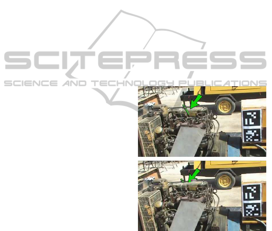
Figure 1 shows an example of the occlusion prob-
lem when a custom AR system has been used in the
on-site repair process of a six-cylinder diesel engine.
Concretely, the pictures included in this figure show
the step when the first of six fuel injectors (mod-
eled using eye-catching green colors) is fitted into
the proper engine cylinder head. The top picture of
this figure shows how a non-ocludded 3D computer-
generated fuel injector is visualized over the engine
indicating the mechanic a misleading final location of
the cylinder head. In this sense, the AR tool seems
to indicate that the current fuel injector should be lo-
cated into one of the cylinder heads located in the
front side of the engine as observed from the user’s
point of view. Otherwise, the bottom picture of the
same figure shows how this augmented fuel injector
has been correctly occluded by the foreground real
objects in the scene, indicating the proper location of
the cylinder head within the back side of the engine.
Figure 1: An example of the occlusion problem in an AR
system for industrial purposes.
In this paper, we propose an easy-to-use AR au-
thoring tool including occlusion capabilities. This
AR tool, called SUGAR, has been intentionally de-
signed to enable a rapid prototyping of low-cost AR
systems. SUGAR allows describing industrial task,
such as assembly, repairing and maintenance proce-
dures as a set of sequential steps including differ-
ent digital contents: video, images, text, manufac-
GRAPP 2012 - International Conference on Computer Graphics Theory and Applications
378

ture’s manuals, and augmented reality information.
Since our AR authoring tool does not use a propri-
etary format, any kind of device (PDA/smartphones,
TabletPC, See-Through goggles, etc.) could be used
for the AR applications generated by the proposed
tool. Moreover, the iterative development process
of an AR application and the corresponding mainte-
nance phase can be completed with our tool by de-
velopers with non-programming skills. Unlike other
authoring tools include some types of occlusion capa-
bilities (Haringer and Regenbrecht, 2002), they deal
with the occlusion problem using a model-based ap-
proach (Breen et al., 1996). This approach registers
3D geometric models of the real objects in the envi-
ronment, denoted as phantom models, to their real-
world counterparts. Since the 3D modeling of ob-
jects involved in the on-site industrial tasks would be
an impossible or a very expensive procedure, our ap-
proach uses Kinect (Santos et al., 2011) for comput-
ing a depth map of the scene to produce occlusion
effects. The application examples show, unlike other
recent easy-to-use AR authoring tools (Wang et al.,
2010), that the proposed tool can be used as a general-
purpose and low-cost framework for generating dif-
ferent maintenance and repair AR applications. Also,
this paper describes some experiments that test the
relative effectiveness of AR instructions in assembly,
maintenance and repair tasks. In this sense, three in-
structional media were compared to evaluate the per-
formance of the developed AR applications: a printed
manual, computer assisted instruction (CAI) using a
TabletPC display, and CAI utilizing a head-mounted
display. The evaluation results show that overlaying
3D instructions on the actual work pieces reduced the
error rate for an assembly task by 79%, particularly
diminishing cumulative errors (errors due to previ-
ous assembly mistakes). Moreover, the time required
by non-programming users using SUGAR to develop
the AR prototypes was much lower (approximately a
95%) than the time required for developing the same
prototypes with expert programmers. These results
validates the proposed tool as a general-purpose AR
authoring tool for industrial AR applications.
The rest of the paper is organized as follows: Sec-
tion 2 shows some related work about AR author-
ing tools for maintenance and repair tasks. Section 3
describes in detail the proposed AR authoring tool.
Next, Section 4 shows different application examples
of the proposed tool, and Section 5 shows the perfor-
mance evaluation of AR instructions in an assembly
task using the proposed tool. Finally, section 6 shows
some concluding remarks and the future work to be
done.
2 RELATED WORK
Augmented Reality has been tested in manufacturing
environments since more than one decade ago (Neu-
mann and Majoros, 1998; Baird and Barfield, 1999).
The potential of AR systems led to national research
projects like ARVIKA (Friedrich, 2002). ARVIKA
was a coordinated project, funded by the German
Government, focused on the use of AR technologies
for supporting working procedures in the develop-
ment, production, and servicing of complex technical
products and systems. Although ARVIKA included
mature concepts for integrating physical and digital
workspaces in a common scenario, the final AR pro-
cedures resulted very poor in terms of intuitive inter-
action mechanisms, functionality and usability. At the
same time, another work proposed a prototype hard-
ware and a software framework for supporting a wide
range of maintenance categories with AR (Schwald
et al., 2003).
More recently, the most remarkable developments
in the field of AR technologies for manufacturing pur-
poses were collected in a remarkable survey (Ong
et al., 2008). Also, another work proved that an
AR application was more efficient than an enhanced
baseline system in reducing time and head movement
during the localization portion of maintenance tasks
(Henderson and Feiner, 2009). The authors were es-
pecially encouraged to achieve these results with a
population of professionally-trained mechanics work-
ing in a field setting, who expressed support for this
approach.
Finally, another recent work includes a question
examination mechanism in the AR authoring tool
(Wang et al., 2010). From a pedagogical point of
view, examination is an important method in under-
standing the efficacy of a system of learning, and this
feature can be a valuable tool also in manufacturing
environments. However, the target users of the pro-
posed authoring tool are high school students, and the
examination mechanism is limited in that study to this
population. In this work, we propose an examination
mechanism suitable for different target populations as
well as a performance evaluation carried out using
qualified participants into the experiments. Also, an
important feature in this proposal is the fact that this
AR authoring tool does not use a proprietary format,
and any kind of device (with an adequate interface)
can use the information generated by the authoring
tool. The authoring tool models AR procedures as a
set of sequential steps, which can be attached with dif-
ferent digital content including AR information with
occlusion capabilities. Once the AR procedure has
been modeled, the editor generates a very simple ex-
AN OCCLUSION-AWARE AR AUTHORING TOOL FOR ASSEMBLY AND REPAIR TASKS
379
change file containing all the digital content as well
as XML data. This exchange file can be loaded into
different AR hardware platforms such as TabletPC,
PDA/smartphones or even another type of devices, in-
cluding low-power general purpose processors, to ex-
ecute the AR procedures in on-site industrial environ-
ments.
3 AN OVERVIEW OF SUGAR
SUGAR (which stands for System for the devel-
opment of Unexpensive and Graphical Augmented
Reality application) is an open-source software plat-
form designed to enable a rapid prototyping of low-
cost AR systems. Our framework is oriented to de-
velop complex AR software applications based on
procedural simulations, which are modeled following
an easy-to-use AR authoring editor. This AR editor
generates an exchange file, describing the AR proce-
dure, which can be loaded into different AR devices
not requiring high computational power.
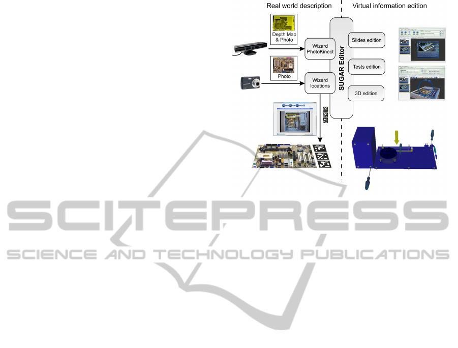
Figure 2 shows the workflow for the development
of AR applications using SUGAR. The SUGAR edi-
tor allows users with non-programming skills the cre-
ation of augmented reality procedures based on steps.
The main challenge when creating an Augmented Re-
ality application is to achieve a correct overlap (regis-
tration) between the real world and the virtual infor-
mation that is added on the real world. SUGAR al-
lows the creation of virtual contents through an easy
edition mechanism based on real world photos. The
user takes photos of the real scenarios to be aug-
mented, and is on these photos where the virtual con-
tent is edited. The ARToolKitPlus-based markers
are automatically generated with a simple calibration
step, in such a way that the user should only paste the
AR markers on the real object in order to visualize the
augmented scene. Therefore, SUGAR bridges the gap
between virtual information and the real world, offer-
ing the user an easy way of creating virtual contents
according to reality.
The SUGAR modules can be classified in two
groups: description of the real world, and virtual con-
tent edition. The first group includes those modules
necessary for creating the scenarios where the virtual
contents will be displayed. Each scenario is com-
posed of an image of the real environment, some AR
markers that are generated automatically, and a depth
map (the latter one only is presented if a Kinect is
available when the photo is taken). In order to cre-
ate this scenario, two wizards guide the user through
some easy stages. The first stage, called the Pho-
toKinect Wizard module, displays the real-time im-
Figure 2: Proposed workflow for the development of AR
applications using SUGAR.
age of the markers camera and allows taking photos
storing at the same time the depth image. This depth
information will be used later in order to produce cor-
rect occlusions. The other wizard, called Locations
wizard, allows the user the creation of a scenario from
either a conventional photo or a photo captured with
AR markers. This wizard is also split into four easy
substages: first, the desired images are loaded. Then,
the wizard allows to draw a rectangle indicating a flat
area where the markers can be located. The two final
substages consists of the introduction of the flat area
defined within the real image and the number of AR
markers to be used. After these steps, the scenario
is ready for editing the virtual contents. The virtual
models will be adjusted to the size of the real object
to be augmented by using the size information intro-
duced by the user. At any moment, the user can select
a scenario and print the associated markers in order to
paste these markers on a real object. This simple wiz-
ard allows a user with neither programming, nor AR-
ToolKit/ARToolKitPlus knowledge, the creation of an
AR marker with the proper size and the correspond-
ing associated configuration file. The absence to this
editor would require that the user selects the images
of the markers to be used (he also locates the markers
in the correct position) and he finally creates a config-
uration file with the description of the size, location
and rotation matrix of each of the markers within the
image.
After the creation of the scenarios, the other group
of modules includes the procedures for defining the
virtual information. The editor of SUGAR uses a
structure based on steps (denoted also as slides),
where each of them is associated to one of the scenar-
ios previously created. The edition of the virtual con-
GRAPP 2012 - International Conference on Computer Graphics Theory and Applications
380
tent can be split into three different stages: definition
of the current step of the procedure, creation of the
virtual content associated to each slide, and the def-
inition of the corresponding evaluation tests for this
step, if necessary. The definition of the slides includes
some basic office functions: creation, ordering, text
edition, aspect, associated video, associated pdf files,
etc. All these functions can be easily performed, in a
similar way to the creation of a conventional graphic
presentation.
The creation of virtual content consists of adding
some virtual elements that help to explain each step
to the scenario displayed in the slide. The virtual ele-
ments can be created either from basic 3D objects or-
ganized in an internal 3D library, or loading 3D mod-
els previously created using Autodesk 3DS Max. The
included 3D library consists of cubes, spheres, planes,
cones, etc., which can be grouped to generate more
complex models, and allows changing their textures,
colors, or other properties. Also, we have developed
an animation module based on keyframes that allows
to animate the virtual objects. In order to allow the
creation of 3D models that are appropriate for the sce-
nario to be augmented, the 3D scene includes a tem-
plate with the photo that is used as the model, and
even (depending on the type of scenery) a mesh cre-
ated from the picture taken with Kinect. Using this
reference, the user only has to locate the virtual mod-
els on the template. This way of creating a scene,
starting from a reference image, allows the location
of the virtual elements and their size adjustment. The
absence of this template would force the user not only
to accurately measure the location of each virtual el-
ement and its orientation on the real object according
to the ARToolKitPlus marker, but also requiring from
the user a certain level of knowledge in 3D design,
computational trigonometry and the use of the AR-
ToolKitPlus library.
Figure 2 also shows how we have created a Test
Wizard for the test edition process. This module can
easily generate three kinds of questions: true/false
questions, multiple answer questions, and selection
on the image. The latter one consists of asking the
user to mark a concrete area on the image (for exam-
ple, a car battery). When creating the test, the user
enters the photo and he marks each vertex of the cor-
rect area with the mouse.
3.1 Software Architecture
The software architecture of SUGAR is based on a
modular approach oriented to develop procedural AR
systems. Basically, the SUGAR framework consists
of two applications: an easy-to-use editor for AR
procedures and an AR light viewer. Both applica-
tions share some software modules permitting them
to reuse 3D-tracking data structure models, and visu-
alization code.
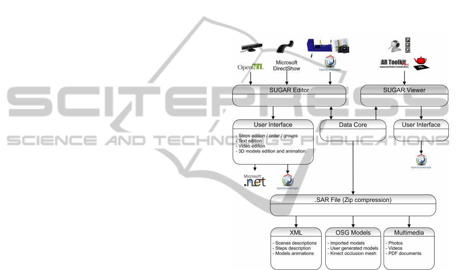
Figure 3 shows the software architecture of the
SUGAR framework for the development of AR en-
vironments. Both applications (“SUGAR Editor” and
“SUGAR Viewer”) share the kernel of the AR frame-
work denoted as “Data Core”. This kernel provides
basic services for augmented reality facilities as cam-
era tracking, marker handling and virtual object inter-
action.
Figure 3: A modular view of the software architecture in
SUGAR.
Although AR editor and AR viewer share this
software module, each application includes a differ-
ent user’s interface. Thus, the graphical user inter-
face of the AR editor has been developed on Windows
Forms and includes some components, developed on
OpenSceneGraph, in order to offer high-performance
3D graphical capabilities when users create and edit
the AR procedures. In this sense, the OpenNI soft-
ware library allows accessing the depth map of the
real scene using the Kinect device. Moreover, the
Microsoft DirectShow API enables high-quality play-
back of streaming video and audio to be attached
to the steps of the industrial (maintenance, repair
or even assembly) procedures. In contraposition to
this multiview 3D application, the AR viewer cor-
responds to a light Windows application, developed
on Qt/C++ (Blanchette and Summerfield, 2008), em-
bedding a reduced version of the OpenSceneGraph
AN OCCLUSION-AWARE AR AUTHORING TOOL FOR ASSEMBLY AND REPAIR TASKS
381
framework and including a reduced set of primitives
for this 3D high-level library tool. Since Qt/C++ is
a cross-platform development framework, the same
source code for a Qt application can be compiled on
different operating systems without changes. In this
sense, the “SUGAR Viewer” has been ported to Sym-
bian and Android operative systems with minimum
changes within the initial source code. The reduced
computation workload of this multiplatform applica-
tion allows the viewer to be executed on low-power
general purpose processors to execute the AR proce-
dures in on-site industrial environments.
The “Data Core” module also includes the defi-
nition and the basic properties of the exchange file
format for the SUGAR framework, denoted as SAR
files. These files are generated by the AR editor to
be imported by the SUGAR multiplatform viewers.
Basically, the SAR files are zip-compressed archives
containing a structured representation of AR applica-
tions, and the corresponding multimedia content, that
can be attached to the steps of the modeled AR proce-
dures for industrial task. The organization of the dig-
ital content, including the depth maps obtained from
the Kinect device, has been defined using XML files,
providing a flexible configuration mechanism.
4 APPLICATION EXAMPLES
In order to validate our AR editor as an efficient tool
for the rapid prototyping of AR applications for as-
sembly, maintenance and repair purposes, we have
tested our tool in four different application exam-
ples belonging to various industrial areas. Concretely,
these application examples are the following proce-
dures: the replacement of the cut heading within a
lathe machine (metal machining area), the assem-
bly of a computer starting from its basic components
(computer and electronics manufacturing area), the
repair of the admission system in a mobile lighting
tower(maintenance of heavymachinery area), and the
review of the spark plugs and the ignition coils on a
BMW M3 E92 (420CV) engine (automobile mainte-
nance area). We have denoted these procedures as
PROC 1 to PROC 4, respectively. Table 1 shows the
amount of steps, gathered into groups, needed to com-
plete each one of the tasks. Since not all the steps rec-
ommended by the manufacturer need visual indica-
tions to be completed, this table also shows, for each
procedure, the number of steps that actually include
AR contents.
In order to help in the completion of these tasks,
SUGAR authoring tool was used to prototype two dif-
ferent AR systems (for each of the four procedures
Table 1: Decomposition of the procedures in steps.
Procedure Groups Steps AR Steps
PROC 1 6 51 26
PROC 2 5 25 20
PROC 3 7 58 32
PROC 4 4 15 10
considered): a computer assisted instruction system
using a TabletPC system (we will denote this AR sys-
tem as S2) and a computer assisted instruction sys-
tem using a head-mounted display (we will denote
this AR system as S3). Concretely, the S2 system
was developed on a Dell Latitude XT1 TabletPc (In-
tel Core 2 Duo at 1.2GHz, 2GB RAM, ATI Radeon
Xpress 1250, Windows 7 Professional) including a
LCD-CCFL 12.1-inch screen for outdoor environ-
ments, reaching up to 400cd/m2 of brightness. The
S3 system consists of the same Dell Latitude XT1 but
connected to an ”AR Vision 3D HMD”, which is a full
stereoscopic video see-through AR device including a
binocular SVGA (1024x768) displays and two sepa-
rate 752x480 (60 FPS) color cameras. In order to il-
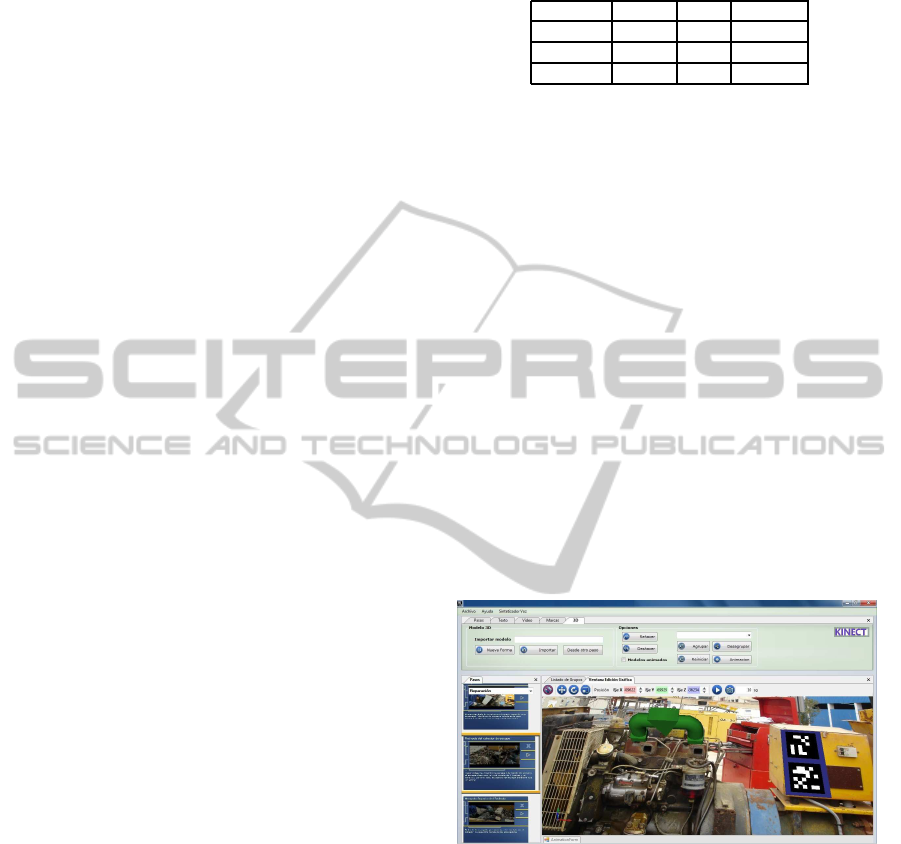
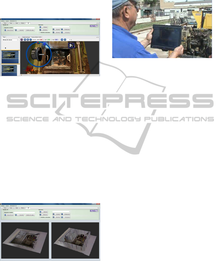
lustrate the considered application examples, Figure 4
shows a snapshot of the proposed AR editor (SUGAR
Editor) when implementing Procedure 1, while Fig-
ure 5 shows a snapshot of the SUGAR tool when used
for Procedure 3.
Figure 4: SUGAR Snapshot for Procedure 1.
Figure 4 and Figure 5 show the interface of the
proposed AR editor for sequential procedures in-
cluded in SUGAR. The easy-to-use interface of the
editor is very similar to the most common graphic pre-
sentation programs (such as Microsoft PowerPoint,
Apple KeyNote, Open Office Impress, etc.), and it
consists of a large view of the current step of the
modeled procedure along with a view of the rest of
steps (as a slide sorter) on the left side of the screen.
The editor allows non-programming users to create
AR applications consisting of a set of sequential steps
handled by AR markers. In this sense, the toolbars
on the top of the window allow to include multimedia
GRAPP 2012 - International Conference on Computer Graphics Theory and Applications
382
contents such as video, images, text, manuals and AR
information into the steps of the AR procedure.
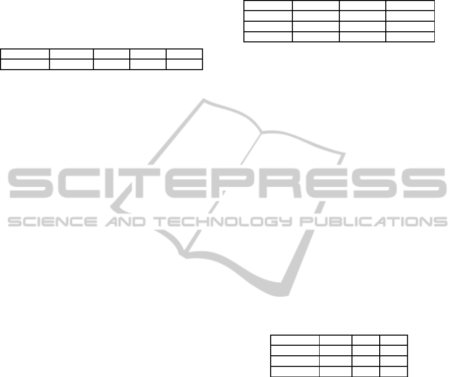
Figure 5: SUGAR Snapshot for Procedure 3.
Figure 5 shows the ”Affine Transformation Tool-
bar” that appears when 3D models (modeled using
Autodesk 3DS Max or selected from a library in-
cluded within the applications) are included into the
current step of the procedure. This toolbar allows
rotating, scaling, translating and defining animation
for the 3D models that will be visualized by the user
when the system recognize the AR markers located as
a part of the environment. Also, the button located at
the right upper corner of the screen allows to load a
depth map of the real scene using the Kinect device.
This feature is needed when the 3D model for the cur-
rent step of the AR procedure needs occlusion capa-
bilities. Figure 6 shows and example of an original
image from a real environment and the correspond-
ing color mapped depth image obtained by the Kinect
device. Finally, Figure 7 illustrates the use of the S2
system when Procedure 1 was tested in a real indus-
trial environment.
Figure 6: Results of the image form the original environ-
ment and the textured depth map using Kinect in SUGAR.
Figure 7: Real use of S2 system in Procedure 1.
5 PERFORMANCE EVALUATION
The performance evaluation of augmented reality au-
thoring tools results in a complex task, since it is very
difficult to quantitatively show the utility or effective-
ness of the proposed methodology and tools. The
measurement of costs reduction in software develop-
ment and maintenance neither results an easy task.
The main reasons are the lack of objective metrics in
not only Augmented Reality, but also Virtual Reality,
and the qualitative and even fuzzy nature of most soft-
ware engineering studies (Seo and OhM, 2007).
A possible way of evaluating the performance
of Augmented Reality tools is a qualitative, user-
centered approach (Traskback et al., 2003). Accord-
ing to recent studies (Nilsson et al., 2010), the obser-
vations and questionnaire are the basis for a qualita-
tive analysis. The questionnaire consists of several
questions where the participants in the evaluation of
the AR tool can freely answer on their experience
of the AR system. The questions are usually related
to overall impression of the AR system, experienced
difficulties, experienced positive aspects, what they
would change in the system and whether it is possi-
ble to compare receiving AR instructions to receiving
instructions from an instructor. However, a qualitative
approach does not allow neither to compare different
AR tools on a fair basis, nor to evaluate their per-
formance in comparison with traditional training or
guidance tools. On the contrary, a quantitative anal-
ysis can allow a fair comparison of different tools.
Some metrics like cost efficiency, development time
and maintainability have been proposed for a quan-
titative analysis (Abawi et al., 2004). However, that
work does not define concrete criteria for assigning
values to the three metrics, and only the development
time is accurately measured.
We propose a quantitative approach for the per-
formance evaluation of the AR tool in some industrial
environments. In order to measure the complexity of
AN OCCLUSION-AWARE AR AUTHORING TOOL FOR ASSEMBLY AND REPAIR TASKS
383
the assembly, repair and maintenance tasks, we have
followed the criteria proposed in (Campbell, 1988).
Therefore, we have classified the application exam-
ples described in Section 4 as shown in Table 2.
Table 2: Classification of the task complexity.
Procedure PROC 1 PROC 2 PROC 3 PROC 4
Complexity Very High Normal High High
In order to measure the performance provided by
the AR systems prototyped with SUGAR, we have
first measured the average completion time required
by fifteen different users in order to completely exe-
cute each of the considered procedures. All the users
were experts technicians in their area, but a training
session was performed prior to the performance eval-
uation in order to allow the users to get in contact
with the AR technology. The same users were used
for performing the four procedures, in order to avoid
any skew in the results due to the different skill of dif-
ferent populations. However, the fifteen users were
divided into four groups, and the sequence of proce-
dures executed by each group was different, in order
to avoid skews in the experimental results due to the
potential training with the technology. Moreover, not
only it was the first time that the users executed the
considered procedures, but also any of the groups re-
peated the same procedure using different systems, in
order to avoid the benefit with the knowledge and ex-
perience that they acquire before.
For comparison purposes, the users also per-
formed the considered procedures exclusively using
a printed manual provided by the manufacturer. We
have denoted this ”system” as S1. Table 3 shows
the average completion times required when using
each system for all the procedures considered. As
it could be expected, the average completion times
for systems S2 and S3 are much lower than the ones
achieved with S1 system. Also, this table shows that
the times achieved with S3 (computer assisted in-
structions (CAI) using a head-mounted display) are
lower than the ones achieved with S2 (CAI using a
TabletPC display), reaching even less than half the
time required for the same procedure with system S1
(in Procedures 1, 3 and 4). These results show the
significant benefits that AR systems can provide to as-
sembly, repair and maintenance tasks.
In order to get a more in-depth analysis of the re-
sults shown in Table 3, we have measured the mis-
takes made when executing the AR procedures for all
the considered experiments. Table 4 shows the av-
erage number of steps in the experiments that were
repeated by the qualified participants because of hu-
Table 3: Completion times with different systems.
Procedure S1 S2 S3
PROC 1 4h 30min 2h 30min 1h 45min
PROC 2 50min 35min 30min
PROC 3 6 h 3h 30min 2h 45 min
PROC 4 2h 1h 15min 50min
man errors. As it could be expected, the direct visual
guidance provided by the augmented reality devices
in systems S2 and S3 resulted in a significant decrease
in the number of repeated stages, compared to the use
of manufacture’s manuals in S1. The system S2 pro-
vides the lowest number of repeated stages. Since the
execution of assembly and maintenance/repair tasks
are often incremental processes, where the results of
previous steps are the input of next steps, undetected
mistakes in preceding stages (denoted as cumulative
errors) result in repeating all the previous affected
tasks, starting where the mistake was committed. For
this reason, the number of the repeated tasks grows
exponentially as the errors made by the participants
increase. Nevertheless, the differences between S2
and S3 systems become significant even if taking into
account this fact, showing that immersive augmented
reality does not provide the best performance in in-
dustrial environments.
Table 4: Number of repeated stages when completing the
AR procedures.
Procedure S1 S2 S3
PROC 1 12.25 2.65 3.30
PROC 2 7.51 1.26 4.65
PROC 3 14.13 2.40 3.60
PROC 4 4.33 1.23 1.57
Nevertheless, Tables 3 and 4 do not actually mea-
sure the performance of SUGAR, but the prototypes
developed with this AR authoring tool. In order to
measure the performance achieved with SUGAR, we
have asked two different teams to develop the pro-
totypes whose results are shown in Table 3. One of
the teams (we will denote this one as Team 1) was
composed of AR programmers, and the other one (we
will denote this one as Team 2) was exclusively com-
posed of expert technicians. As a reference, we asked
Team 1 to develop the prototype following the clas-
sic AR development approach, by writing, compiling
and debugging source code. In this sense, Team 1
developed the AR prototypes using Microsoft Visual
Studio 2010 as C++ development framework, Open-
SceneGraph 2.9.7 as 3D graphics visualization toolkit
and ARToolKitPlus 2.2 as software library for AR
purposes. In order to measure the performance of
GRAPP 2012 - International Conference on Computer Graphics Theory and Applications
384
SUGAR, we asked Team 2 to develop the same pro-
totypes with SUGAR.
Table 5 shows the development times (in work-
ing days) required by each team. The column labeled
as “Team” shows the team, the column labeled as
“Param.” shows the specific parameter of the develop-
ment time measured by each row, and the other four
columns shows the results for each procedure. The
parameters measured are the following ones: SLOC
measures the final number of source lines of code in-
cluded within the final AR prototype, while FPS indi-
cates the frame-rate (in frames per second) achieved
using the test hardware. The parameter CT mea-
sures the number of working days required by the
team for completing the coding stage of the prototype.
The parameter DT measures the number of working
days required by the team for completing the debug-
ging/adjusting stage, and the parameter TT measures
the total time required for the development of the pro-
totype (the sum of CT and DT parameters).
Table 5: Source-code sizes and development times.
Team Param. PROC 1 PROC 2 PROC 3 PROC 4
1 SLOC 71853 64710 76254 53695
FPS 28 44 32 50
CT 95 76 108 59
DT 15 10 17 6
TT 110 86 125 65
2 SLOC 79215 71523 37749 60101
FPS 31 40 35 50
CT 3 3 2 2
DT 1 1 2 1
TT 4 4 4 3
Table 5 shows that the size of the source code
generated by SUGAR is roughly a 10% higher than
the source code created by traditional AR program-
ming. However, this slight increase of the source code
does not have an effect on the graphic performance
of the AR application. Moreover, Table 5 also shows
that the time required by non-programmingusers with
SUGAR to develop the AR prototypes are less than
5% of the ones required for developing the same pro-
totypes with programmers. These differences of or-
ders of magnitude show the potential that an intuitive
AR authoring tool like SUGAR can provide to in-
dustrial environments. Moreover, the ease of use of
SUGAR allows to avoid the need for programming
skills, exclusively requiring the expertise of techni-
cians in that field for developingAR prototypes. Also,
any potential change required by the prototype can
also be made by technicians, without the need of pro-
gramming skills.
6 CONCLUSIONS AND FUTURE
WORK
In this paper, we have proposed an easy-to-use AR
authoring tool, which allows the easy creation of in-
teractive augmented reality applications without any
programming knowledge. This authoring tool in-
cludes an easy-to-use editor for AR procedures and
an AR light viewer, which share non-proprietary ex-
change files describing the AR procedures. The pro-
posed tool allows the development of AR applications
with occlusion capabilities to be used in on-site in-
dustrial procedures, where a certain level of depth-
perception is necessary. Unlike other recent propos-
als, our tool does not rely on expensive or unavailable
3D models, and it uses Kinect for computing a depth
map of the scene.
The performance evaluation of the proposed AR
authoring tool includes both a qualitative and a quan-
titative assessment. Concretely, we have tested four
AR applications, belonging to different industrial ar-
eas, using different instructional media. The perfor-
mance evaluation results show that the registration
of geometric models to the real-world counterparts
in industrial procedures significantly facilitate work-
ers their actual on-the-job tasks. The direct visual
guidance provided by the AR devices significantly de-
crease the number of repeated stages when compared
to commonly used manufacture’s manuals.
Also, the time required by users with non-
programming skills to develop the AR prototypes us-
ing our tool was much lower than the time required
for developing the same prototypes with expert pro-
grammers when following a classical development of
AR systems. These results shows the potential of our
approach and validates it as a general-purposeAR au-
thoring tool for industrial AR applications.
As a future work to be done, we are working on
new versions of the light viewer for iOs and Windows
Phone devices. Moreover, SUGAR pretends to inte-
grate a new tracking module, based on natural fea-
tures, to improve the current augmented reality ex-
perience provided by the tool when executing on-site
industrial tasks.
ACKNOWLEDGEMENTS
This work has been jointly supported by the Span-
ish MICINN and the European Commission FEDER
funds under grants Consolider-Ingenio CSD2006-
00046 and TIN2009-14475-C04-04.
AN OCCLUSION-AWARE AR AUTHORING TOOL FOR ASSEMBLY AND REPAIR TASKS
385

REFERENCES
Abawi, D. F., Luis, J., Arcos, L., Haller, M., Hartmann, W.,
Huhtala, K., and Trskbck, M. (2004). A mixed reality
museum guide: The challenges and its realization. In
Proceedings of the 10th International Conference on
Virtual Systems and Multimedia (VSMM 2004).
Azuma, R. (1997). A survey of augmented reality.
Presence: Teleoperators and Virtual Environments,
6(4):355–385.
Baird, K. and Barfield, W. (1999). Evaluating the effec-
tiveness of augmented reality displays for a manual
assembly task. Virtual Reality, 4:250–259.
Blanchette, J. and Summerfield, M. (2008). C++ GUI Pro-
gramming with Qt 4. Open Source Software Develop-
ment Series. Prentice Hall.
Breen, D. E., Whitaker, R. T., Rose, E., and Tuceryan, M.
(1996). Interactive occlusion and automatic object
placement for augmented reality. Computer Graph-
ics Forum, 15(3):11–22.
Burns, D. and Osfield, R. (2004). Open scene graph a: In-
troduction, b: Examples and applications. In Proceed-
ings of the IEEE Virtual Reality Conference 2004 (VR
2004), page 265.
Campbell, D. J. (1988). Task complexity: A review and
analysis. Academy of Management Review, 13(1):40.
Cawood, S. and Fiala, M. (2008). Augmented Reality: A
Practical Guide. Pragmatic Bookshelf.
Friedrich, W. (2002). Arvika-augmented reality for devel-
opment, production and service. In In Proceedings
of the IEEE/ACM International Symposium on Mixed
and Augmented Reality (ISMAR02),, pages 3–4.
Hampshire, A., Seichter, H., Grasset, R., and Billinghurst,
M. (2006). Augmented reality authoring: generic con-
text from programmer to designer. In In Proceed-
ings of the Australasian Computer-Human Interaction
Conference (OZCHI’06), pages 409–412.
Haringer, M. and Regenbrecht, H. T. (2002). A pragmatic
approach to augmented reality authoring. In Proceed-
ings of the 1st International Symposium on Mixed and
Augmented Reality, ISMAR ’02, pages 237–, Wash-
ington, DC, USA. IEEE Computer Society.
Henderson, S. J. and Feiner, S. (2009). Evaluating the bene-
fits of augmented reality for task localization in main-
tenance of an armored personnel carrier turret. In Pro-
ceedings of the 2009 8th IEEE International Sympo-
sium on Mixed and Augmented Reality, pages 135–
144. IEEE Computer Society.
Kato, H. and Billinghurst, M. (1999). Marker tracking
and hmd calibration for a video-based augmented re-
ality conferencing system. In Proceedings of Inter-
national Workshop on Augmented Reality (IWAR’99),
pages 85–94.
Ledermann, F. and Schmalstieg, D. (2005). April: A high-
level framework for creating augmented reality pre-
sentations. In In Proceedings of the IEEE Virtual Re-
ality Conference 2005 (VR 2005), pages 187–194.
MacIntyre, B., Gandy, M., Dow, S., and Bolter, J. (2005).
Dart: a toolkit for rapid design exploration of aug-
mented reality experiences. ACM Transactions on
Graphics (TOG) - Proceedings of ACM SIGGRAPH
2005, 24(3).
Neumann, U. and Majoros, A. (1998). Cognitive, perfor-
mance, and systems issues for augmented reality ap-
plications in manufacturing and maintenance. In In
Proceedings of the IEEE Virtual Reality Annual Inter-
national Symposium (VR ’98), pages 4–11.
Nilsson, S., Johansson, B., and Jnsson, A.(2010). The Engi-
neering of Mixed Reality Systems, chapter A Holistic
Approach to Design and Evaluation of Mixed Reality
Systems, pages 33–55. Human-Computer Interaction
Series. Springer.
Ong, S. K., Yuan, M. L., and Nee, A. Y. C. (2008). Aug-
mented reality applications in manufacturing: a sur-
vey. International Journal of Production Research,
46(10):2707–2742.
Poupyrev, I., Tan, D., Billinghurst, M., Kato, H., Regen-
brecht, H., and Tetsutani, N. (2001). Tiles: A mixed
reality authoring interface. In Proceedings of Con-
ference on Human-Computer Interaction (INTERACT
’01), pages 334–341.
Sang-Cheol, P., Sung-Hoon, L., Bong-Kee, S., and Seong-
Whan, L. (2005). Tracking non-rigid objects using
probabilistic hausdorff distance matching. Pattern
Recognition, 38(12):2373–2384.
Santos, E. S., Lamounier, E. A., and Cardoso, A. (2011).
Interaction in augmented reality environments using
kinect. In Proceedings of the 2011 XIII Symposium on
Virtual Reality, SVR ’11, pages 112–121, Washing-
ton, DC, USA. IEEE Computer Society.
Schmalstieg, D. (2005). Rapid prototyping of augmented
reality applications with the studierstube framework.
In In Proceedings of the Workshop of Industrial Aug-
mented Reality (IAR), IEEE/ACM International Sym-
posium on Mixed and Augmented Reality (ISMAR05).
Schwald, B., Laval, B. D., Sa, T. O., and Guynemer, R.
(2003). An augmented reality system for training and
assistance to maintenance in the industrial context. In
In Proceedings of 11th International Conference in
Central Europe on Computer Graphics, Visualization
and Computer Vision, pages 425–432.
Seichter, H., Looser, J., and Billinghurst, M. (2008). Com-
posar: An intuitive tool for authoring ar applica-
tions. In In Proceedings of the IEEE/ACM Interna-
tional Symposium on Mixed and Augmented Reality
(ISMAR08), pages 177–178.
Seo, J. and OhM, S. (2007). Pvot: An interactive author-
ing tool for virtual reality. International Journal of
Computer Science and Network Security (IJCSNS),
7(4):17–26.
Traskback, M., Koskinen, T., and Nieminenl, M. (2003).
User-centred evaluation criteria for a mixed reality au-
thoring application. In Proc. of Tenth International
Conference on Human-Computer Interaction (HCI),
pages 1263–1267.
Wagner, D. and Schmalstieg, D. (2007). Artoolkitplus for
pose tracking on mobile devices. In Proceedings of
12th Computer Vision Winter Workshop (CVWW’07),
pages 139–146.
Wang, M., Tseng, C., and Shen, C. (2010). An easy to
use augmented reality authoring tool for use in ex-
amination purpose. Human-Computer Interaction,
332:285–288.
GRAPP 2012 - International Conference on Computer Graphics Theory and Applications
386
