
A PROCEDURAL GEOMETRY MODELING API
Pedro Brandão Silva
1
, António Coelho
1,2
, Rui Rodrigues
1
and A. Augusto Sousa
1,2
1
INESC Porto, Departamento de Engenharia Informática, Faculdade de Engenharia, Universidade do Porto,
Rua Dr. Roberto Frias, 4200-465, Porto, Portugal
2
3Decide / Palcos da Realidade, Pólo de Industrias Criativas, Praça Coronel Pacheco, 2, 4050-453 Porto, Portugal
Keywords: Geometry Modeling, CAD API, Procedural Modeling, Virtual Urban Environments.
Abstract: This paper presents a solution for geometric manipulation in procedural modeling as an Application
Programming Interface (API). This approach intends to enable a more powerful control over the geometric
entities by performing selections based on their attributes, similar to picking features in graphical interfaces.
This is achieved through the definition of a topological structure, which features a set of properties, such as
scope, spatial localization and semantic information. The applicable modeling operations allow a more
customized control, as well as successive tracking, which induce a greater, faster and more intuitive
approach for geometry generation. This approach still constitutes ongoing work, but has already been
successfully applied for the generation of large virtual urban environments.
1 INTRODUCTION
An API - Application Programming Interface –
provides an abstraction to a problem, specifying how
to interact with the software components that
implement that same problem. These are typically
distributed through software code libraries, allowing
its use by multiple applications. In short, APIs,
define reusable code blocks that allow certain
feature sets to be incorporated into final applications
(Reddy, 2011).
In the area of geometric modeling, many APIs
have already been conceived and are currently
employed in some of the most popular
tridimensional authoring tools, such as AutoCAD or
Solid Works, used in various areas of engineering,
architecture and media production, among others.
Using visual interfaces for interaction, users are able
to perceive the whole extent of their work while, at
the same time, being able to navigate deep into the
details of the created geometries for custom
manipulation. When an operation is meant to be
applied to a specific group of geometric elements
(vertex, edge, face…), the user just needs to select
them with its pointing device (an action commonly
known as “picking”). While this sort of interaction is
ideal and possible for individual and manual creation
of tridimensional models, it is not compatible with
the procedural paradigm of content generation.
The use of procedural methods for generating
three-dimensional content is becoming more
frequent and has been delivering very interesting
results at a lesser effort cost, by generating three-
dimensional models with much less human
interaction.
Procedural methods require that the user,
capturing the knowledge about the modeling
process, introduces some guidelines and rules. It is
also possible to start from existing shapes or general
information from existing data sources. In this sense,
some methods have already been conceived, but as
far as control is concerned, procedural ways still
lack powerful picking and manipulation facilities to
apply geometric operations. This motivates the
development of more advanced methodologies for
such control.
The paper presents the PGCAD API, a solution
for geometric manipulation in procedural modeling
tools. It enables a more powerful control over
geometric entities based on their properties and
sequential application of modeling operations,
therefore allowing a greater, faster and more
intuitive approach for geometry generation.
This paper is structured as follows: first, some
related work will be presented, followed by the
description of PGCAD API, where its architecture
and features will be detailed, but not without
explaining some important concepts first. Some
information regarding the implementation will come
129
Brandão Silva P., Coelho A., Rodrigues R. and Augusto Sousa A..
A PROCEDURAL GEOMETRY MODELING API.
DOI: 10.5220/0003848101290134
In Proceedings of the International Conference on Computer Graphics Theory and Applications (GRAPP-2012), pages 129-134
ISBN: 978-989-8565-02-0
Copyright
c
2012 SCITEPRESS (Science and Technology Publications, Lda.)

next, followed by the results section, which includes
its discussion. Lastly, the conclusions and some
future work will be described.
2 RELATED WORK
This subject fits into the area of Geometry Modeling
Kernels on the one hand, as well as Procedural
Modeling on the other hand, and both already
possess an average number of interesting solutions
by various researchers and companies.
The 3D ACIS Modeler (Spatial Corporation,
2011) is a commercial modeling component
developed by Spatial Corporation. Among other
features, the creators highlight their advanced
surface and solid modeling capabilities, as well as
their simple, flexible and interactive interface.
Parasolid is a commercially licensed geometric
modeling kernel now proprietary of Siemens PLM
Software (Siemens PLM Software, 2010). It
advertises many surface manipulation tools, Boolean
operators, extrusion, embossing, patterning, lofting,
sweeping, thickening, hollowing and many other
modeling operations.
Open Cascade (OPEN CASCADE S.A.S., 2011)
is a powerful CAD component developed by Open
CASCADE S.A.S., and consists in free open source
C++ libraries. Among other features, their
topological structure is stressed, along with the
various modeling operations, primitive instantiation
and rendering capabilities.
SMLib (Solid Modeling Solutions Inc., 2011) is
another geometry modeling kernel, developed by
Solid Modeling Solution Inc., based in NURBS
curves and surfaces combined with a topological
non-manifold structure. The company emphasizes
the choice over a Boundary representation which
induced the possibility to model any tridimensional
model, and with high efficiency.
IRIT (Elber, 2009) is a solid geometry modeling
environment that allows 3D modeling based on
primitives and Boolean operations to connect them
(CSG – Constructive Solid Geometry). Its original
creator, Gershon Elber, stresses also its simultaneous
potential for freeform curve and surface
manipulation tools.
Although the mentioned list of tools is not, by
any means, extensive, it contains an overview on the
most popular geometry modeling tools, enumerating
some of the its most interesting and powerful
features any modeler should possess. However, as
said, the paradigm is not procedurally-oriented.
On the other hand, concerning the area of
procedural modeling, there is also a considerable
amount of work.
L-Systems (an acronym for Lindenmayer
Systems) are amongst the most popular approach for
procedural generation in computer graphics, having
been initially employed, by Aristid Lindenmayer in
the simulation of plant and organism growth
(Prusinkiewicz & Lindenmayer, 1996). The behavior
of the development sequence of an L-System can be
parameterized and configured, allowing the control
over the modeling processes. Parish and Müller
employed the same methodology to generate
extensive street networks (Parish & Müller, 2001).
Geospatial L-Systems (Coelho, Bessa, Sousa, &
Ferreira, 2007) are an extension of parametric L-
Systems which incorporates spatial awareness. This
approach combines the ability of data amplification
provided by the L-Systems with the geospatial
awareness of geospatial systems.
Wonka et al. introduced the split grammars
(Wonka, Wimmer, Sillion, & Ribarsky, 2003), a
new type of parametric set grammar based on the
concept of shape brought up by Stiny and Gips
(Stiny, 1980; Stiny & Gips, 1972), also with
applications in the field of modeling architectural
buildings. He also presented an attribute matching
system oriented by a control grammar, offering the
flexibility required to model buildings with many
different styles and designs. Based on this work,
Müller et al. developed the CGA Shape (Müller,
Wonka, Haegler, Ulmer, & Gool, 2006), a shape
grammar capable of producing extensive
architectural models with high detail. The CGA
Shape is a sequential grammar (such as the
Chomsky Grammar (Chomsky, 1956)), therefore all
the production rules are applied in sequence, in order
to allow the characterization of the structure. The
implementation of the CGA Shape is integrated in
the CityEngine framework (Procedural Inc., 2009).
Considering that text-based shape definitions were
impractical to use by most artists, Lipp presented in
(Lipp, Wonka, & Wimmer, 2008) a visual editing
system which introduced traditional modeling
techniques, allowing a more intuitive and powerful
control over each grammar aspect.
3 THE PGCAD API
PGCAD is a geometric modeling kernel oriented for
procedural modeling. Its name stands for Procedural
Generation Computer-Aided Design and aims at
providing a more powerful control over the
development of procedural modeling processes, by
GRAPP 2012 - International Conference on Computer Graphics Theory and Applications
130
allowing actions and operations to be executed based
on each element properties and previously applied
operations. This is only possible due to the object-
oriented nature of all PGCAD-involved elements.
Before the overall features can be explained, it is
necessary for some architecture basics to be
presented.
3.1 Topology
PGCAD topological structure is based on a polygon
mesh representation, having been inspired by Open
CASCADE (OPEN CASCADE S.A.S., 2011) and
OGC’s Simple Features (Open Geospatial
Consortium Inc., 2006) specification. The conceived
modeling kernel has therefore the following basic
geometric elements:
Shape: The basic, not instantiable, abstract
element, from which all the remaining ones inherit
from, sharing therefore some common attributes.
Vertex: A single point in 3D space owning, in its
simplest form, a reference to its position.
Edge: A line connecting two vertices. By
definition, an edge does not possess an orientation.
Wire: A set of connected and sequential edges,
joined by common vertices.
Face: A planar polygon, having its external
boundary defined by a closed, non self-intersecting
wire, and a set of internal holes, also defined as by
wires with the same requirements.
Shell: A set of faces connected by their edges or
wires.
Solid: A closed shell of planar faces, therefore a
polyhedron.
Compound: An element which groups sets of
shapes, including other compounds.
3.2 Shape Properties
Besides the geometrical component, the concept of
shape in PGCAD relies on four fundamental aspects:
scoping, materials, spatial localization and
semantics.
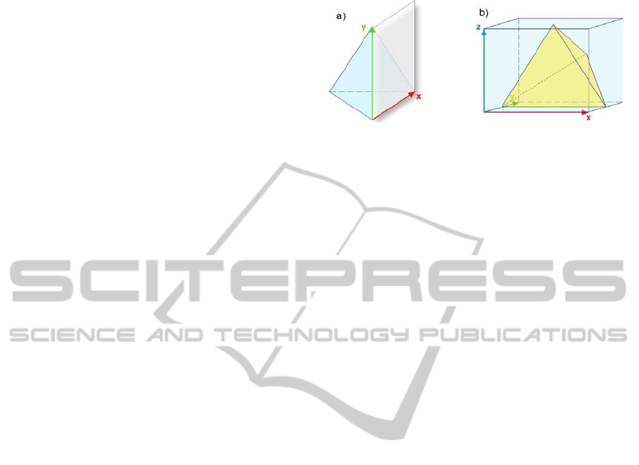
The purpose of scope is to store information
concerning the orientation and size of the shape, a
concept similar to the one found in the CGA Shape
(Müller, et al., 2006). In short, each shape has a
reference for its coordinate system, in order to
facilitate operations internal to the structure of the
shape (for example, texture mapping). According to
the type of shape, the scope format may vary, but is
in most cases defined by a point of origin and 3
sized axes, which can indicate also the dimension of
a line, bounding rectangle or bounding box,
depending on the type of shape (see Figure 1).
Figure 1: Shape scoping in PGCAD, exemplified for faces
(a) and solids (b). Note that on (a) the z-axis vector is not
displayed, since it is of zero size.
Spatial localization in PGCAD is essential in
order to achieve spatial awareness features. This
concept consists in allowing shapes to be aware of
their surrounding elements, a fact that might be
important when operating on the shape. Supposing
that one’s goal is to connect a vertex with all its
neighboring ones within a certain distance, such
operation could use spatial awareness to avoid the
need to indicate each one of the items to connect to.
Another, not exactly related, property of shapes
is its material. Each can possess certain lighting and
rendering options, such as color, light reflectance
(ambient, diffuse, specular), shininess, texture, etc.,
which can be afterwards be interpreted by the
renderer to visualize the shapes.
Finally, and perhaps the most important
characteristic of shapes is the possibility to
continuously store semantic information. Each shape
has a container of “Labels”, each being able to hold
a set of key-value pairs related to its meaning,
location, applied operations or any other fact.
Labeling can be done at any time, being especially
useful to keep track of a model’s evolution process.
In the end, by having additional semantics, the
integration of the generated geometry with more
interactive applications could be done more easily.
3.3 Shape Properties
The development of shapes can be done in two
ways. One strategy is to manually create complex
shapes by joining more basic shapes through their
direct references. For instance, starting with a list of
vertices:
L1 = [Vertex(0,0,0), Vertex(0,5,0), Vertex(5,0,0)]
(1)
One can transform it into a wire:
W1 = Wire(L1)
(2)
And afterwards into a face:
F1 = Face(W1)
(3)
A PROCEDURAL GEOMETRY MODELING API
131
and so on, always using direct references to the
shapes. In theory, it is possible to build very
complex models using this approach. However,
although this is essential for the first steps and
usable as long as there are a reduced number of
shapes, it is not effective when masses of shapes are
considered.
A second methodology, supported by PGCAD, is
to use modeling operations, similar to what can be
found in any geometry modeling API. PGCAD,
however, features two major differences in how
operations can be applied:
1. Operations can be applied to entire sets of
shapes, which follow a specific condition;
2. Operations can be applied to entire sets of
shapes, where the parameters can be based
on each shape’s properties.
Modeling operations are objects, which can be
instanciated as such. This allows a greater set of
parameters to be added, without the need to define
multiple object constructors.
To better explain the concept of operation, an
example of face extrusion will be presented.
Considering a list of shapes Ls1, an operation
instance (which must be given a tag), receiving this
list as shape data input.
Extr1 = FaceExtrusion(“Extr1”, Ls1)
(4)
This operation will only consider faces, ignoring
any other types of shape that the list may contain. If
additional filters are intended, they must be
specified:
Extr1.SetCondition(shape => ((Face)shape).area > 20 || 2 > 5 ||
myVariable == 15)
(5)
The definition of conditions can be achieved
through lambda expressions, which allow the
condition to be based on each shape property, a
simple Boolean expression or by using external
variables (5).
So far no extrusion value has been defined. That
constitutes another interesting feature of PGCAD.
While the value can be the same for all the selected
faces (6), it can also be defined base on each face’s
properties (7):
Extr1.SetValue(Vector(0,0,10))
(6)
Extr1. SetValue(shape => ((Face)shape).normal * 10)
(7)
Once the operations properties have been
defined, the process may start.
Ls2 = Extr1.Apply()
(8)
The output is a list of shapes, which includes all
shapes, including:
The non-face shapes;
The faces which did not match the
conditions;
The original faces which were operated on;
The newly created faces.
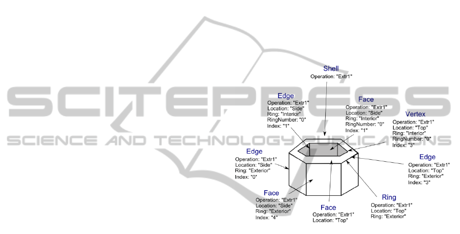
Out of this list it would be now useful to select
them apart. This is possible due to the automatic
labeling, where labels are applied to all generated
elements according to a specific mapping, which is
different according to the modeling operation. In
case of face extrusion, where shells, faces, rings,
edges and vertices are created, labeling occurs as
demonstrated in Figure 2.
Figure 2: Automatic labeling of a holed face, after being
extruded. Due to the high number of shapes and labels,
only a demo subset is shown.
It is possible to query the list of shapes according
to the applied labels. There is a common key-value
combination that has been added to all the shapes
that have been created in the process of face
extrusion: “Operation” => “Extr1”, based on the
indicated parameter at the beginning of the action
(See (4)). Filtering such shapes can be done in the
following way, also using lambda expressions:
Ls3 = Ls2.Where(shape => shape.Labels.Exists(
label => label[“Operation”] == “Extr1”))
(9)
However, it is important to understand what kind
of shapes was actually added in the process of the
modeling operation. In the case of face extrusion, a
shell shape is added, which means that Ls3 contains
now only the shells. They must now be unfolded to
the intended type.
Ls4 = CreateShapeList(Ls3, ShapeType.Edges)
(10)
In (10) a list of edges was created, by unfolding
the higher order shapes (shells into faces, faces into
GRAPP 2012 - International Conference on Computer Graphics Theory and Applications
132
rings, rings into edges), and discarding them. It is
now possible to select, for instance, the vertical
edges at the inner side of the model through the
following statement (based on Figure 2):
Ls5 = Ls4.Where(shape => shape.Labels.Exists(
label => label[“Location”] == “Side” &&
label[“RingNumber”] == 0))
(11)
4 IMPLEMENTATION
PGCAD has been implemented in Microsoft’s .NET
C# 4.0, whose managed, object-oriented nature
facilitated its topological definition and integration.
One of its most useful features, which made this API
flexible query definition possible, is Microsoft-
specific extensible, general-purpose language LINQ
(language-Integrated Query), as well as the
possibility to use Lambda Expressions. Both these
features influenced also PGCAD’s approach and
syntax, due to their ease of use and effective
application.
In order to be able to visualize the produced
results, the Microsoft XNA Framework (Microsoft
Corporation, 2011), a popular game development
framework, was used. An intermediate layer
between PGCAD and XNA has been conceived, in
order to integrate the geometric kernel’s topological
elements to the rendering engine data structures.
Such approach makes it directly possible for the
API to be used in digital games.
5 RESULTS AND DISCUSSION
As a starting example to test PGCAD’s methodology
and specification, an application focused on the
popular research area of virtual urban area
generation has been conceived (Coelho, et al., 2007;
Müller, et al., 2006; Procedural Inc., 2009; Wonka,
et al., 2003).
By starting with some real-world GIS Data, the
geometries were imported and converted using
PGCAD’s import and conversion capabilities. The
used information concerned building, block and road
information, which had to be correctly integrated
using PGCAD’s spatial localization abilities.
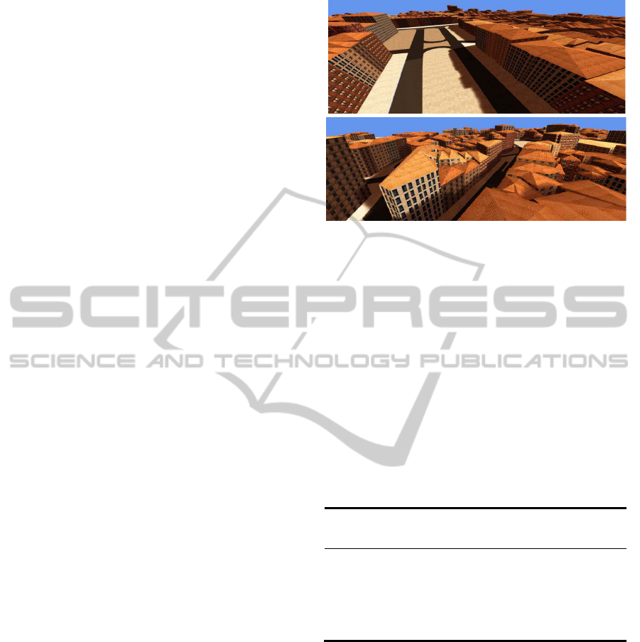
At this point, PGCAD only supports a limited
number of modeling operations, such as extrusion,
texture mapping, geometric transformations, roof
construction and material application. Still, they are
enough to produce quality models, as it can be seen
in Figure 3.
Figure 3: Application of the PGCAD geometry kernel to
the procedural modeling of the downtown of the city of
Porto, Portugal.
Concerning the efficiency of the modeler, PGCAD
appears to perform very well. Although the number
of applied operations per object (building, block or
street) was reduced, it is important to consider the
total number of objects. Table 1 indicates the
measured times for different-sized city areas. It is
important to note that, since information is loaded
from a GIS data source, disk access must also take
place, and is included in the measured times. Also,
many optimizations can still be done.
Table 1: Performance test of PGCAD on a Intel Core 2
Duo 2,53Ghz, 3GB RAM, Windows 7 32-bit Laptop.
Area Time
Loading
Time
Generation
Time
Base
Entities
Faces Vertices
1 ha 636ms 323ms 313ms 74 1053 2299
5ha 838ms 400ms 438ms 242 3764 7906
10ha 1000ms 493ms 507ms 478 7355 15165
100ha 2985ms 1345ms 1640ms 2198 32413 67890
Its speed suggests that it could be employed for
real-time generation in virtual reality applications,
such as games, where the virtual environment is
created on-the-fly.
6 CONCLUSIONS AND FUTURE
WORK
In this paper, the PGCAD API has been presented as
a new geometric modeling solution for procedural
tools whose main characteristic lies on the powerful
control given over the manipulated geometric
entities. This is achieved through its intuitive
A PROCEDURAL GEOMETRY MODELING API
133

topological structure, which features a set of
properties, such as scope, spatial awareness and
semantic information. The modeling processes can
be massively applied to sets of shapes, yet act
according to each individual shape’s properties. This
allows a more customized control, as well as
successive tracking, which induce a greater, faster
and more intuitive approach for geometry
generation.
PGCAD is still undergoing development, but has
already been applied in the field of virtual urban
environment generation, with promising results in
reduced time, proving its usability in real-time
applications such as games. Its concept of spatial
awareness and semantic control constitute PGCAD’s
most novel features, which will continue to be
explored, as well as its mass modeling process,
which can operate based on each shape’s properties.
Other current limitations, such as the scarce number
of higher-level modeling operations, will also be
subject of future attention, so that richer and more
detailed objects can be created.
ACKNOWLEDGEMENTS
This work is partially supported by the Portuguese
government, through the National Foundation for
Science and Technology - FCT (Fundação para a
Ciência e a Tecnologia) and the European Union
(COMPETE, QREN and FEDER) through the
project PTDC/EIA-EIA/108982/2008 entitled
“3DWikiU – 3D Wiki for Urban Environments" and
through the Ph.D. Scholarship SFRH / BD / 73607 /
2010.
REFERENCES
Chomsky, N. (1956). Three Models for the Description of
Language. (IRE Trans. Information Theory (2),), 113–
124.
Coelho, A., Bessa, M., Sousa, A. A., & Ferreira, F. N.
(2007). Expeditious Modelling of Virtual Urban
Environments with Geospatial L-systems. Computer
Graphics Forum, 26(4), 769-782.
Elber, G. (2009). The IRIT modeling environment. from
http://www.cs.technion.ac.il/~irit/
Lipp, M., Wonka, P., & Wimmer, M. (2008). Interactive
visual editing of grammars for procedural
architecture. Paper presented at the ACM SIGGRAPH
2008 papers.
Microsoft Corporation. (2011). App Hub. Retrieved
18/6/2011, from www.xna.com
Müller, P., Wonka, P., Haegler, S., Ulmer, A., & Gool, L.
V. (2006). Procedural Modeling of Buildings. Paper
presented at the ACM SIGGRAPH 2006 Papers.
OPEN CASCADE S.A.S. (2011). Open CASCADE.
Retrieved 12/3/2011, from http://www.opencascade.
org/occt/
Open Geospatial Consortium Inc. (2006). OpenGIS®
Implementation Specification for Geographic
Information - Simple feature access - Part 1: Common
Architecture. In J. R. Herring (Eds.)
Parish, Y. I. H., & Müller, P. (2001). Procedural Modeling
of Cities. (SIGGRAPH 2001), 301–308.
Procedural Inc. (2009). 3D Modelling Software for Urban
Environments. Procedural Retrieved 26/2/2011, from
http://www.procedural.com/
Prusinkiewicz, P., & Lindenmayer, A. (1996). The
Algorithmic Beauty of Plants: Springer-Verlag.
Reddy, M. (2011). API Design for C++: Morgan
Kaufmann.
Siemens PLM Software. (2010). Parasolid brochure.
Solid Modeling Solutions Inc. (2011). SMLib™ - An
advanced geometric modeling kernel. from http://
www.smlib.com/smlib.html
Spatial Corporation. (2011). 3D ACIS Modeling.
Retrieved 11/3/2011, from http://www.spatial.com/
products/3d-acis-modeling
Stiny, G. (1980). Introduction to shape and shape
grammars. Environment and Planning B, 7(3), 343-
351.
Stiny, G., & Gips, J. (1972). Shape Grammars and the
Generative Specification of Painting and Sculpture.
Paper presented at the Information Processing '71.
Wonka, P., Wimmer, M., Sillion, F., & Ribarsky, W.
(2003). Instant architecture. Paper presented at the
ACM SIGGRAPH 2003 Papers.
GRAPP 2012 - International Conference on Computer Graphics Theory and Applications
134
