
AN AUGMENTED REALITY SYSTEM BASED ON LIGHT FIELDS
A. Quintana
1
, R. Quir
´
os
1
, I. Remolar
1
and E. Camahort
2
1
Institute of New Image Technologies, Universitat Jaume I, Castel
´
on, Spain
2
Dept. de Sistemas Inform
´
aticos y Computaci
´
on, U. Polit
´
ecnica de Valencia, Valencia, Spain
Keywords:
Augmented Reality, Light Fields.
Abstract:
The development of augmented reality systems that combine virtual elements with the real world is currently
increasing. This paper presents an augmented reality system that renders the virtual elements from models
based on the light fields. The use of these models allow us to obtain higher level of photorealism than rep-
resentations that render polygons. Using light fields also allows us to keep constant the rendering time. The
presented system has been implemented using the Open Source library ARToolKit and a spherical model of
the light field based on the direction-and-point parameterization (DPP) with some associated depth informa-
tion. The system has been validated using different light fields, and it has been compared its performance with
a classic version of the ARToolKit library based on VRML files. The presented augmented reality system can
be applied to the visual inspection of synthetic objects of great complexity or based on real images.
1 INTRODUCTION
Augmented Reality (AR) is a technique that extends
the real-world environments with some virtual objects
that appear in the user views. AR allows 3-D virtual
objects to be integrated into a 3-D real environment
in real time. Its application is very common in some
fields such as computer-assisted surgery, education or
entertainment (Azuma, 1997). The main problem of
this technique is to achieve a low response time of the
system while ensuring a good integration between the
real and virtual elements. The real-virtual integration
improves by using models with a high level of real-
ism, however the high geometric complexity of this
type of models does not allow to achieve a satisfac-
tory response time.
The recent advances in the field of information
technology and communications have enabled the de-
velopment of mobile devices with sophisticated fea-
tures such as the iPhone, or some PDAs, usually
equipped with a small camera. These devices allow to
run augmented reality applications that superimpose
on the real image some very simple virtual objects,
such as annotations, images and 3D objects modeled
with very few polygons (Wagner and Schmalstieg,
2009).
As an alternative to geometry-based models, im-
age based rendering techniques (IBR) provide a high
realism having a constant rendering time, independent
of the geometric or structural complexity of the repre-
sented virtual elements. The Light Field is an image-
based modeling technique that represents the objects
as a 4D function from the plenoptic function (Gurrea,
2001). Models based on Light Fields allow us to ren-
der objects both synthetic and real, with a high degree
of realism and a constant time, which makes it suit-
able for use in augmented reality.
Taking this modeling technique into account, this
paper presents an augmented reality system based on
a open source library (ARToolKit) (ARToolKit, 2011)
that uses the light field as augmentation model. This
article is organized as follows. It starts reviewing the
current state of augmented reality techniques and the
light field model. Next, it is described the implemen-
tation of the presented system. Finally, the obtained
results are evaluated and some works are proposed to
be done in the future, extending this work.
2 PREVIOUS WORK
In this section we will briefly review the current
state of augmented reality techniques and the light
field model. Some comprehensive reviews have been
published for both techniques (Azuma, 1997) (Shum
et al., 2003), so this section focuses on the aspects
directly related to the work presented in this article.
453
Quintana A., Quirós R., Remolar I. and Camahort E..
AN AUGMENTED REALITY SYSTEM BASED ON LIGHT FIELDS.
DOI: 10.5220/0003852204530459
In Proceedings of the International Conference on Computer Graphics Theory and Applications (GRAPP-2012), pages 453-459
ISBN: 978-989-8565-02-0
Copyright
c
2012 SCITEPRESS (Science and Technology Publications, Lda.)

2.1 Augmented Reality
The term Augmented Reality was developed in 1990
by Thomas Caudell to refer to a system used in Boe-
ing to assist the cable assembly of aircraft. In 1997
Azuma (Azuma, 1997) gave the first definition of aug-
mented reality as a system that:
• combines reality with virtual elements,
• is interactive, and
• renders 3D objects.
One of the most important aspects to be consid-
ered in the design and implementation of an aug-
mented reality system is the environment that it is go-
ing to represent. This consideration will determine its
features and complexity. In the literature, several sys-
tems have been developed that manage both indoor
and outdoor environments. Indoor environments are
much less restrictive, allowing the use of more pow-
erful computers and fixed systems based on a previous
training of the environment. In outdoor environments,
the user has to transport the entire system, which lim-
its the available processing capacity. Moreover, the
impossibility of preparing or controlling a hostile en-
vironment, subjected to extreme magnetic phenom-
ena, light or weather changes and other natural phe-
nomena appears.
Depending on the environment that is represented
and the future application, an augmented reality sys-
tem is composed of the following elements:
• A processing system.
• A visualization device.
• A monitoring system.
The processing system can be a fixed or portable
computer, PDA or mobile phone. The choice depends
on the work environment and the process capability
required by the application.
The display device is the part of the system re-
sponsible to render the augmentation. The potential
devices can be divided into two groups: the ones
based on optical technologies and the ones based on
video. On one hand, in the systems based on optical
technologies, the user directly observes the real scene,
overlapped by the synthetic image by means of opti-
cal combiners. These devices are usually mounted on
the user’s head, such as virtual reality helmets. They
usually present some problems such as ghosting, eye
strain or fatigue. On the other hand, the video-based
systems, by contrast, combine a video sequence from
the actual scene, captured with one or more cameras,
with synthetic images by mixing video techniques.
The advantages of this kind of systems are their sim-
plicity and cost, since they only require a personal
computer and some USB or Firewire video cameras.
Furthermore, the availability of a sequence of real-
world video allows us to use tracking systems based
on the detection of characteristic traits using computer
vision techniques.
Finally, the tracking system is in charge of estimat-
ing the position and orientation of the the real-world
view to augment. The type of system to be used is
determined by the environment in which the applica-
tion is going to be applied and by the utilized display
system. In an optical-technology-based system, some
sensors have to be used to implement the monitoring
system. However, in a video-based system can be ap-
plied computer vision techniques that complement the
use of sensors, such as GPS receivers, magnetic sen-
sors (bars), inertial sensors (accelerometers and gyro-
scopes) among others.
In recent years, some augmented reality systems
based on video have been proposed that perform the
monitoring by detecting characteristics or features of
the image. The insertion of markers in known posi-
tions in the real environment facilitates the monitor-
ing, but requires prior preparation of it.
Since the initial proposals at the beginning of the
90’s, augmented reality systems have been applied in
fields such as medical visualization, repair, assembly
and maintenance of machinery, planning of actions
for robots, entertainment, education or construction,
among others (Azuma, 1997). Most of these appli-
cations require very complex and expensive systems
and they usually operate in interior environments. Al-
ternatively, in recent years, some applications have
been implemented that use a personal computer or
mobile device, a webcam and a set of low cost sen-
sors. Among them, we highlight the animated base-
ball cards for sale in the United States, or Wikitude
World Browser for the iPhone (Wikitude, 2011).
Many of the proposals about low cost applications
use open source libraries, such as ARToolKit (AR-
ToolKit, 2011). ARToolKit includes a tracking sys-
tem based on markers that allows us to show three-
dimensional objects superimposed on the real image
captured by a camera. Its main advantages are the
availability of the code and the few requirements on
devices (a computer and a video camera), so it be-
comes an ideal platform for developing augmented
reality applications. Its main drawback is the need
to prepare the work environment by placing mark-
ers, which makes it difficult to use in outdoor envi-
ronments. However, this library has been used in nu-
merous applications indoors (Kwon and Park, 2005)
(Asai et al., 2004) (Nischelwitzer et al., 2007), and in
some outdoor applications combined with other mon-
itoring techniques (Guo et al., 2008).
GRAPP 2012 - International Conference on Computer Graphics Theory and Applications
454

In ARToolKit, objects superimposed on the mark-
ers can be displayed using the OpenGL library or
loading a VRML model. In both cases, these rep-
resentations are adapted for rendering on specialized
graphics hardware. However, it should be noted that
photorealistic rendering involves a considerable loss
in rendering speed (Kang et al., 2000).
2.2 Light Fields
The image-based rendering techniques (IBR) are tra-
ditionally proposed as an alternative to geometry-
based rendering for generating images of both real
and synthetic objects. These techniques are indepen-
dent of the geometric complexity of the represented
objects. Moreover, they are really efficient in render-
ing images of a scene from different viewpoints by
combining samples of available images.
Different approaches have been proposed to
this technique: from the point-based representation
(Levoy and Whitted, 1985) to the most innovative
proposals in which a large number of images are used
to render different viewpoints, interpreting these im-
ages from a 4D function obtained from the plenoptic
function (Adelson and Bergen, 1991).
Light fields were firstly introduced by Levoy and
Hanrahan (Levoy and Hanrahan, 1996) and Gortler et
al. (Gortler et al., 1996). The light field allows us
to represent complex geometric objects defined as the
visible radiance in a point in one determined direc-
tion. From this data, it is possible to obtain the repre-
sentation of the light flow of all lines passing through
the point of view of a scene. This method allows us
to synthesize non-existent images through a filtering
process and the interpolation of some available im-
ages, ensuring a correct visual perspective.
The plenoptic function was initially defined in
(Adelson and Bergen, 1991) as the intensity of the
light rays passing through the center of the camera
for any point (V
x
, V
y
, V
z
) in all possible angles (θ, φ)
for each wavelength λ and in every time t, as it is ex-
pressed in Equation 1.
P
7
= P(V
x
, V
y
, V
z
, θ, φ, λ, t) (1)
Adelson and Bergen (Adelson and Bergen, 1991)
considered as a essential task to achieve a useful and
compact description for the local properties of this
function. This idea was echoed by Wong et al. (Wong
et al., 1997) who introduced (θ, φ) as the light direc-
tion to ensure control of the lighting. McMillan and
Bishop (McMillan and Bishop, 1995) introduced the
concept of full plenoptic modeling from a 5D function
considering the static environment (Equation 2).
P
5
= P(V
x
, V
y
, V
z
, θ, φ) (2)
This new definition of the plenoptic function was
reduced to a 4D function in (Levoy and Hanrahan,
1996) by considering a occlusion-free space as a re-
sult of the no-variable behavior of the radiance along
a line unless it is blocked. The analysis concludes
with a space-oriented line function, parameterized by
two planes at an arbitrary position. The formulation
is shown in Equation 3,
P
4
= P(u, v, s, t) (3)
where (u, v) and (s, t) are the coordinate systems
of the foreground and background plane respectively.
This type of parameterization is characterized by in-
troducing distortions when performs a representation
of the light field. Other types of representations
present an isotropic parameterization, resulting in a
uniform light field (Camahort et al., 1998).
The image-based rendering techniques offer a
simple acquisition capability and a very realistic rep-
resentation of complex lighting conditions. Among
their advantages, we can highlight their low render-
ing complexity, which depends only on the resolution
of the used images. Moreover, we can use some com-
pression and simplifying image algorithms, more effi-
cient than those applicable to geometric data. Finally,
there is a possibility of using pre-acquired images of
both real and synthetic objects, or even a mixture of
both (Levoy and Hanrahan, 1996).
Different systems have been designed to allow the
acquisition of a light field from a real object or scene
(Liang et al., 2007). The light field model used in this
work is based on a direction and point parameteriza-
tion (DPP) with depth information associated to the
light field radiance. This model can represent mul-
tiple objects with geometric information associated.
The light field is represented as the sampling radiance
data of the lines that intersect the convex hull of the
object. The implementation of the DPP parametriza-
tion is based on a quasi-uniform discretization of the
set of directions in the 3D Cartesian space that con-
verts it to a 2D space. The use of depth information
ensures a higher quality image and low requirement
storage (Escriva et al., 2006).
3 GOALS
The main goal of this work is to design an augmented
reality system that previews a virtual object using a
light-field model. The most important advantages of
using light fields are:
AN AUGMENTED REALITY SYSTEM BASED ON LIGHT FIELDS
455
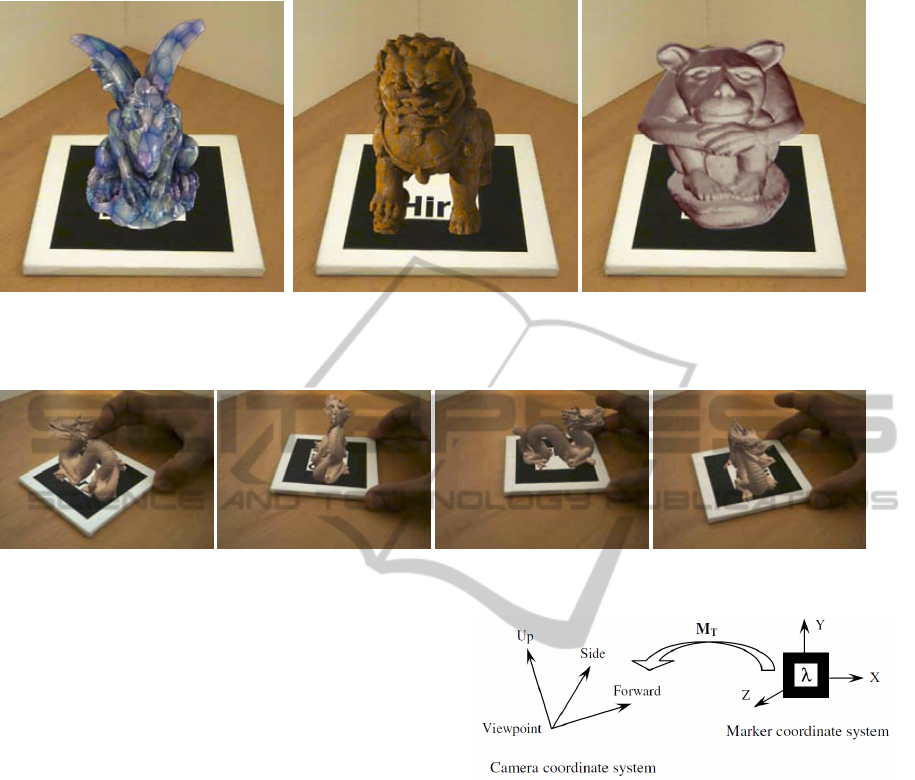
(a) Gargoyle model. (b) Lion model. (c) Umma model.
Figure 1: Screenshots of the light-field representations used in our tests.
Figure 2: Visual inspection of a light field by the manipulation of a marker.
• The visualization time is constant and does not de-
pend on the object’s geometric complexity.
• They allow the visualization of synthetic and real
objects.
These advantages led us to propose an augmented
reality system capable of handling scenes with a high
level of complexity and/or real objects. This devel-
oped system will be very useful in many applications
related to cultural heritage or virtual museum visual-
ization, for instance. As a secondary goal, we pro-
pose the use of a low cost system consisting of a lap-
top computer or a mobile device, a web-cam, and an
open-source library.
4 IMPLEMENTATION
In order to implement the proposed system, the AR-
ToolKit library has been used as augmentation tool
and a DPP-based light-field model with associated
depth information. ARToolKit’s tracking system
gives back a transformation matrix with the informa-
tion about real camera position and orientation. Us-
ing this information, the virtual camera position can
be established to ensure that the virtual object main-
tains a proper alignment with the marker detected in
the image.
Figure 3: Relationship between the coordinate systems of
the camera and the marker M
T
matrix.
The system has been implemented on a DELL
workstation with an Intel Xeon 2.8 GHz preproces-
sor and 1 GB of memory. Regarding the graphics
hardware, it has been used an NVIDIA GeForce 7800
GTX graphic card with 512 MB of memory.
ARToolkits tracking system runs frame by frame.
For each frame the visible marker in the image is de-
tected. Then, the marker with the highest confidence
is selected and it is generated a trasformation matrix.
The tranformation maps the camera coordinate sys-
tem to the coordinate system of the marker selected.
This transformation is stored as a 4x4 matrix (M
T
)
and it is returned to the application for processing (see
Figure 3). The system uses matrix M
T
as the OpenGL
modelview matrix to render the virtual objects.
That way the objects are rendered using a syn-
thetic camera that has been registered with the real
GRAPP 2012 - International Conference on Computer Graphics Theory and Applications
456
camera. We consider extracting the camera coordi-
nate system from matrix M
T
directly. Note that M
T
is
a coordinate system transformation, and its first three
rows contain the director vectors Forward, U p and
Side. The fourth column is related to the viewing po-
sition. These relationships between M
T
and the cam-
era coordinate system are illustrated in the following
equation:
M
T
=
S
X
S
Y
S
Z
T
X
U
X
U
Y
U
Z
T
Y
F
X
F
Y
F
Z
T
Z
− − − −
(4)
Moreover, we extend this library by including a
spherical light-field rendering algorithm, a version of
the Lumigraph algorithm (Gortler et al., 1996). The
validation of the system has been made by testing dif-
ferent light-fields and comparing the response time of
the new algorithm versus the response time of AR-
ToolKit’s original algorithm with VRML objects.
5 RESULTS AND CONCLUSIONS
The new algorithm has been validated using several
synthetic light-fields created in a previous research
project. Figure 1 shows a capture for each one of
them. The rendering of these light-field models is in-
teractive: moving the markers makes it possible to vi-
sualize the objects from different viewpoints. Figure
2 shows the user’s interaction with a light-field and
the ARToolKit’s markers.
As it has been mentioned before, the time neces-
sary to render a light-field is geometrically indepen-
dent. It just depends on the number of images used to
build the model and on their resolutions. Table 1 il-
lustrates some parameters of the used models, and the
time needed to visualize them (in seconds). The res-
olution of the images used to render the models was
256x256. It is important to highlight the results relat-
ing to the rendering time: all the models reach a frame
rate between 10 and 15 frames per second, very close
to real time, when the camera moves around the ob-
ject. The high level of photo-realism of the images
and the constant visualization time, independent of
the geometry, makes it possible to use this system in
the visual inspection of complex virtual models, or
even in light-fields of real objects.
Although the rendering cost of a light-field model
is constant, if the object to represent is geometri-
cally simple, we will get better rendering time with
classical polygonal representations. In order to de-
termine the geometric complexity of a model and to
decide what kind of modeling should be used, some
Table 1: Light fields used in the tests.
Object Polygons Images Time (ms)
gargoyle 478.950 27.300 0.04281
lion 1.311.956 1.700 0.03297
umma 226.705 27.300 0.002969
Table 2: Characteristics of the different levels of detail.
LoD Polygons Vertices
1 871.414 437.645
2 1.742.828 875.290
3 3.485.656 1.750.580
4 6.971.312 3.501.160
5 13.942.624 7.002.320
6 27.885.248 14.004.640
tests have been developed. Our experiments com-
pare the rendering time of visualization a light-field
representation with the one obtained with a classical
ARToolKit version that uses VRML as representation
format. The object to render is Brian Curless’ Dragon,
available in VRML format at the Stanford repository
and its light-field model, also acquired in a previous
project. We evaluated the response time of our sys-
tem by averaging the visualization time (for every 100
process cycles) and comparing the result with the val-
ues returned by ARToolKit when different levels of
detail (LoD) are rendered. Table 2 shows the geo-
metric characteristics of the different levels of detail
involved in the experiment of the VRML model.
The light-field of Brian Curless’ Dragon was
rendered from 27.300 images with a resolution of
256x256, obtained from 47.8950 views. Table 3 com-
pares the rendering time of all the models and Figure
5 shows a comparative chart of these results. The blue
line represents the visualization time, in milliseconds,
as a function of the number of polygons. The red
line represents the visualization time of the light-field
model.
The visual aspect of the light-field representation
Table 3: Rendering time of the different levels of detail.
Time (ms)
Based on Light Fields 0,04281
Based on VRML files
Level of detail 1 0.03578
Level of detail 2 0.03829
Level of detail 3 0.04375
Level of detail 4 0.05391
Level of detail 5 0.07515
Level of detail 6 0.12766
AN AUGMENTED REALITY SYSTEM BASED ON LIGHT FIELDS
457
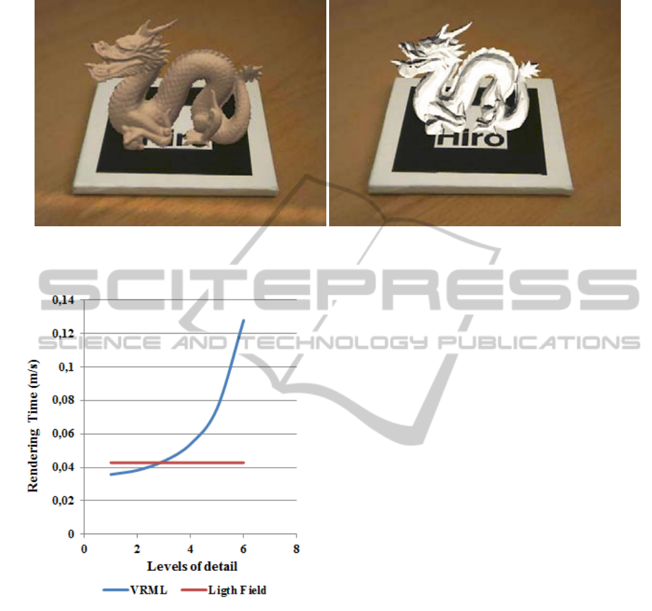
(a) Light field modeling. (b) VRML modeling (LoD 6).
Figure 4: Comparison between both representations in the developed system.
Figure 5: Graphical representation of the obtained results.
in the developed augmented reality system is better
than the one given by the geometric representation,
as Figure 4 shows. Moreover, as the Artoolkit library
was used, it is guaranteed in the developed system an
accurate tracking process, preserving a real sensation
on an augmented environment from different points
of view.
Analyzing the results shown in Table 3 and in Fig-
ure 5, it can be concluded that the use of a light-field
model is more suitable as a way of representation for
geometric models with more than 3 million triangles.
However, if the model to represent is formed by less
than this number of polygons, it is better to render the
model using a geometric representation.
Finally, we can conclude that the use of light-
field models offers a higher visual quality than those
that use geometrical representations, with a stable re-
sponse time. This advance allows us the use of com-
plex synthetic objects or those acquired from real ob-
jects.
6 FUTURE WORK
In order to render light-field models from real ob-
jects, a big amount of images from different view-
points is needed. Nowadays, there exist many sys-
tems that capture spherical light-fields, but they are
limited by the size of the object to be represented, or
are even restricted to acquire the images in the lab,
which is sometimes impossible. It is necessary to
define some unstructured acquisition techniques that
enable the acquisition of an object with a hand-held
camera.
Another problem is the big amount of images
needed to render the actual light-field models; this
implies a high cost of storage. For this reason, it is
necessary to devise new representation techniques in-
volving a smaller amount of images, thus improving
the response time.
Finally, the use of markers reduces the system’s
capabilities only to indoor space. To consider another
tracking system, based on low cost sensor technology,
and the detection of singular features, could be a bet-
ter solution. These modifications allow the use of this
kind of application in outdoor space with mobile de-
vices, depending of the graphic and processing capa-
bilities.
GRAPP 2012 - International Conference on Computer Graphics Theory and Applications
458

ACKNOWLEDGEMENTS
This work was supported by the Spanish Min-
istry of Science and Technology (Project TIN2010-
21089-C03-03) and Feder Funds, Bancaixa (Project
P1.1B2010-08) and Generalitat Valenciana (Project
PROMETEO/2010/028).
REFERENCES
Adelson, E. H. and Bergen, J. R. (1991). The plenoptic
function and the elements of early vision. In Landy,
M. S. and Movshon, A. J., editors, Computational
Models of Visual Processing, pages 3–20. MIT Press.
ARToolKit (2011). Artoolkit user manual, version 2.33.
Asai, K., Osawa, N., Sugimoto, Y. Y., and Kondo, K.
(2004). Operation-support system for transportable
earth station using augmented reality. In Masoodian,
M., Jones, S., and Rogers, B., editors, APCHI, volume
3101 of Lecture Notes in Computer Science, pages 9–
18. Springer.
Azuma, R. T. (1997). A survey of augmented reality.
Presence: Teleoperators and Virtual Environments,
6(4):355–385.
Camahort, E., A., and Fussell, D. S. (1998). Uniformly
sampled light fields. In Rendering Techniques, pages
117–130.
Escriva, M., Domingo, A., Abad, F., Vivo, R., and Cama-
hort, E. (2006). Modeling and rendering of dpp-based
light fields. Geometric Modeling and Imaging–New
Trends, pages 51–56.
Gortler, S. J., Grzeszczuk, R., Szeliski, R., and Cohen, M. F.
(1996). The lumigraph. In Proceedings of the 23rd
annual conference on Computer graphics and inter-
active techniques, SIGGRAPH ’96, pages 43–54.
Guo, Y., Du, Q., Luo, Y., Zhang, W., and Xu, L. (2008).
Application of augmented reality gis in architecture.
In ISPRS08, pages 331–336.
Gurrea, E. C. (2001). 4d light-field modeling and rendering.
Kang, S. B., Szeliski, R., and Anandan, P. (2000). The
geometry-image representation tradeoff for rendering.
In Proceedings ICIP, pages 13–16.
Kwon, Y. and Park, J. (2005). Tangible tele-meeting sys-
tem with dv-arpn (augmented reality peripheral net-
work). In Computational science and its applications
– ICCSA 2005. International conference, Singapore,
May 9–12, 2005. Proceedings, Part I, pages 913–920.
Levoy, M. and Hanrahan, P. (1996). Light field render-
ing. In Proceedings of the 23rd annual conference on
Computer graphics and interactive techniques, SIG-
GRAPH ’96, pages 31–42. ACM.
Levoy, M. and Whitted, T. (1985). The use of points as a
display primitive. In Technical Report 85-022, Com-
puter Science Department,Technical Report 85-022,
Computer Science Department.
Liang, C., Liu, G., and Chen, H. H. (2007). Light field
acquisition using programmable aperture camera. In
ICIP (5), pages 233–236.
McMillan, L. and Bishop, G. (1995). Plenoptic model-
ing: an image-based rendering system. In Proceedings
of the 22nd annual conference on Computer graph-
ics and interactive techniques, SIGGRAPH ’95, pages
39–46.
Nischelwitzer, A., Lenz, F., Searle, G., and Holzinger, A.
(2007). Some aspects of the development of low-cost
augmented reality learning environments as examples
for future interfaces in technology enhanced learning.
In Proceedings of the 4th international conference on
Universal access in human-computer interaction: ap-
plications and services, pages 728–737.
Shum, H., Kang, S., and Chan, S. (2003). Survey of image-
based representations and compression techniques.
IEEE Trans. Circuits Syst. Video Techn., 13(11):1020–
1037.
Wagner, D. and Schmalstieg, D. (2009). Making augmented
reality practical on mobile phones, part 2. IEEE Com-
put. Graph. Appl., 29:6–9.
Wikitude (2011). Wikitude, http://www.wikitude.com/.
Wong, T., Heng, P., Or, S., and Ng, W. (1997). Image-
based rendering with controllable illumination. In
Proceedings of the Eurographics Workshop on Ren-
dering Techniques ’97, pages 13–22.
AN AUGMENTED REALITY SYSTEM BASED ON LIGHT FIELDS
459
