
ISOSURFACE EXTRACTION FROM HYBRID UNSTRUCTURED
GRIDS CONTAINING PENTAHEDRAL ELEMENTS
Akshay Narayan
1
, Jaya Sreevalsan-Nair
1
, Kelly Gaither
2
and Bernd Hamann
3
1
International Institute of Information Technology - Bangalore, 26/C, Electronics City
Hosur Road, Bangalore 560100, India
2
Texas Advanced Computing Center, University of Texas at Austin, 10100 Burnet Road, Austin, TX 78758, U.S.A.
3
Institute for Data Analysis and Visualization, Department of Computer Science, University of California
Davis, One Shields Avenue, Davis, CA95616, U.S.A.
Keywords:
Volume Visualization, Isosurface Extraction, Hybrid Meshes, Marching Methods.
Abstract:
Grid-based computational simulations often use hybrid unstructured grids consisting of various types of ele-
ments. Most commonly used elements are tetrahedral, pentahedral (namely, square pyramids and right triangu-
lar prisms) and hexahedral elements. Extracting isosurfaces of scalar fields defined on such hybrid unstructured
grids is often done using indirect methods, such as, (a) subdividing all non-tetrahedral cells into tetrahedra and
computing the triangulated isosurfaces using the marching tetrahedra algorithm, or (b) triangulating intersec-
tion points of edges of cells and computing the isosurface using a standard triangulation algorithm. Using
the basic ideas underlying the well-established marching cubes and marching tetrahedra algorithms, which
are applied to hexahedral and tetrahedral elements, respectively, we generate look-up tables for extracting
isosurfaces directly from pentahedral elements. By using appropriate look-up tables, it is possible to process
nearly all types of hybrid unstructured grids used in practical applications without the need for indirect meth-
ods. We construct look-up tables for square pyramidal and triangular prismatic cells with accurate topological
considerations.
1 INTRODUCTION
Computer simulations of physical phenomena often
use hybrid unstructured grids with complex geomet-
rical structure. For example, these grids are routinely
used in computational fluid dynamics (CFD) and fi-
nite element analysis (FEA). Performing correct di-
rect interpolation on such hybrid grids, e.g., in the
context of direct volume visualization or isosurface
extraction, is central to its analysis. The complex ge-
ometry and topology, i.e. element connectivity, of
such grids makes its analysis more challenging.
A great deal of progress has been made in re-
cent years in the field of volume rendering using
ray-casting. However, research related to isosurface
extraction from hybrid grids has not been fully ad-
dressed for the entire spectrum of element types,
which are commonly used, apart from hexahedra and
tetrahedra. Some of the commonly used elements,
which we will be focussing on in this work, are shown
in Figure 1(A). We have used the following interpola-
tion models with three linearly independent variables
for these elements:
• Tetrahedron: Linear interpolation, often using
barycentric coordinates, α, β, γ, and δ, is used,
where the following rule applies: α + β + γ + δ =
1.
• Square Pyramid (Pentahedron): Bilinear inter-
polation is used for the base quadrilateral com-
bined with linear interpolation from the base
quadrilateral to the apex, i.e. the opposing single
vertex. (s,t) are used for bilinear interpolation,
and u is the parameter used for linear interpola-
tion along axis.
• Right Triangular Prism (Pentahedron): Linear
interpolation, often performed using barycentric
coordinates, is applied to the two opposite trian-
gular faces (bases) combined with linear interpo-
lation along the axis of the prism, i.e., in the di-
rection from one triangular base to the other. u is
the parameter used for linear interpolation along
the axis and (α,β, γ) are used as barycentric coor-
dinates for the interpolation within the triangular
660
Narayan A., Sreevalsan-Nair J., Gaither K. and Hamann B..
ISOSURFACE EXTRACTION FROM HYBRID UNSTRUCTURED GRIDS CONTAINING PENTAHEDRAL ELEMENTS.
DOI: 10.5220/0003852506600669
In Proceedings of the International Conference on Computer Graphics Theory and Applications (IVAPP-2012), pages 660-669
ISBN: 978-989-8565-02-0
Copyright
c
2012 SCITEPRESS (Science and Technology Publications, Lda.)
P0010
P000
P000
P101
P100
P110
P111
P010
P011
(a) (b)
(c) (d)
P
P
P
P
P1001
P0101
P0011
P0100
P0010
P1000
P0001
P0100
P1000 P100
P110
P010
P001
P001
(Value=5) (Value=2)
(Value=2) (Value=3)
s
t
(Value=3.5)
(a) (b) (c)
P01 P11
P00 P10
(a) (b)
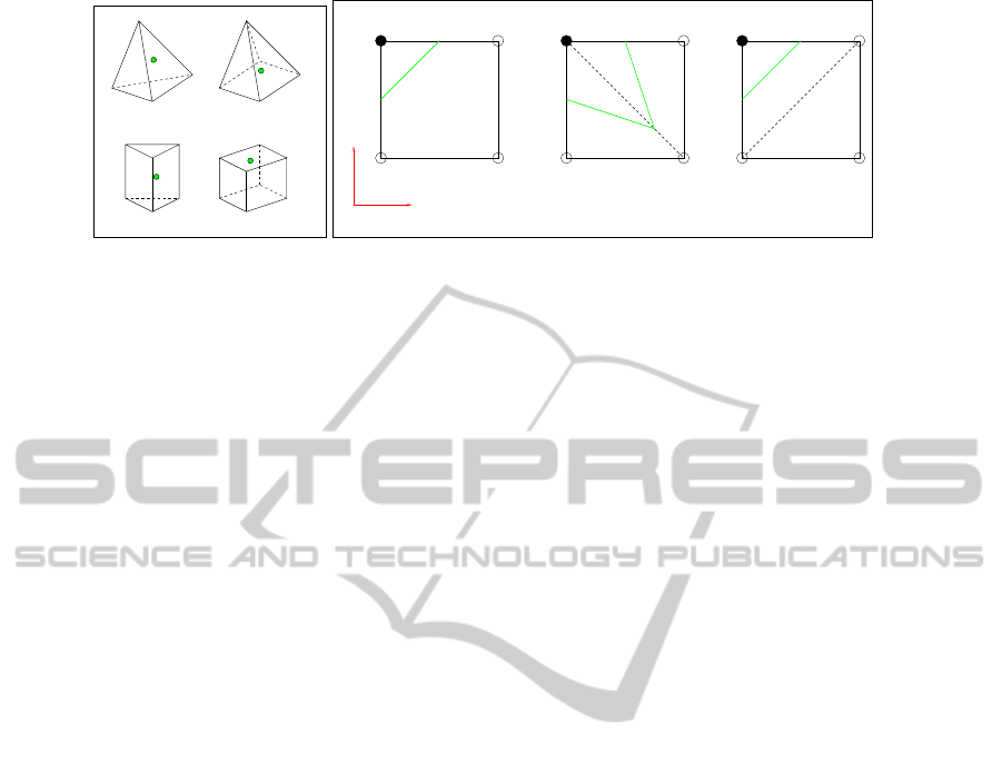
Figure 1: (a) Different element/cell types: (a) Tetrahedron, (b) Pentahedron - Square Pyramid, (c) Pentahedron - Right
Triangular Prism, and (d) Hexahedron. Using parametric representation based on the interpolation models, a point P in space
with respect to each cell is represented as (a) P(α, β,γ, δ), (b) P(s,t,u), (c) P(α, β,γ, u), (d) P(s,t,u). (b) Difference of isolines
without and with triangulation: For extracting isoline for function value 3.5, (a) shows the approximation of isoline using
bilinear interpolation-based contouring, (s,t) being the parametric representation; (b) and (c) show the two different isolines
obtained when considering different triangulations of the quadrilateral. Note that the isolines in (b) and (c) are still topological
homotopes.
bases. The barycentric coordinates follow the fol-
lowing condition: α+ β + γ = 1.
• Hexahedron: Trilinear interpolation is used, with
parametric representation s,t,u, which represent
x-, y-, and z-coordinates respectively.
All parameters of points interior to the cell satisfy the
property of being in the real interval [0, 1]. The mod-
els are popularly used owing to their lower computa-
tional complexity. In addition to these cell types, there
exist several other types of finite elements all having
their own associated interpolation functions. Never-
theless, those other types do not occur in our specific
applications.
The primary reason for lack of efforts has been
that hybrid grids consist of elements or cells whose
basis functions are no longer purely linear or trilin-
ear. This leads to more complex interpolating func-
tions which are more challenging to analyze. How-
ever, recent increase in the availability and accessibil-
ity of powerful computational resources has increased
use of hybrid grids for several CFD and finite element
method (FEM) applications, thus demanding more in-
depth analysis of such grids.
Existing isosurface extraction methods, such as
the commonly used marching cubes or marching
tetrahedra algorithms work well on hybrid grids, sub-
ject to converting a given hybrid grid first to a purely
hexahedral grid or a purely tetrahedral grid, respec-
tively. Converting the hybrid grid, either by resam-
pling the grid to a rectilinear grid, or decompos-
ing the grid elements into tetrahedral elements, in-
troduces additional approximation errors and is not
a unique solution. Additionally, the conversion ap-
proaches scale linearly with problem size, which may
slow down performance for larger datasets.
We attempted to use open source visualization
tools like ParaView (Moreland, 2011), and GMV (Or-
tega, 2011), on a large hybrid grid dataset, whose size
is of the order of 1 GB. However, loading such a large
dataset into the system memory and generating iso-
surfaces required approximately 10 minutes in the se-
rial implementation of ParaView. ParaView’s parallel
implementation showed slightly better performance
than the serial version. It was not possible to obtain
isosurfaces in real time for our specific dataset, which
motivated our research to perform direct extraction of
isosurfaces from hybrid grids. Though our results do
not show any significant improvement in performance
in the case of the large dataset, our work conclusively
analyzes the various topological orientations of the
pentahedral cells so that we obtain a unique isosur-
face for any given value.
The key contribution of our work is to provide
look-up tables to extract isosurfaces directly from
five-node (square pyramidal) and six-node (right tri-
angular prismatic) pentahedral elements, which in-
cludes all topological configurations, and the compu-
tations involved in determining body saddle points for
specifically, the triangular prismatic element. These
look-up tables enable us to obtain a unique solution
for isosurface for a given function value. Addition-
ally, we have used a combination of look-up tables
from the traditional marching tetrahedra and extended
marching cubes, and our proposed tables for pentahe-
dral cells, to use the native elements directly to com-
pute isosurfaces.
2 RELATED WORK
The foundation of our work has been the marching
ISOSURFACE EXTRACTION FROM HYBRID UNSTRUCTURED GRIDS CONTAINING PENTAHEDRAL
ELEMENTS
661

cubes algorithm, which has been extensively re-
searched in the scientific visualization community,
for which (Lorensen and Cline, 1987), (Nielson and
Hamann, 1991), (Nielson, 2003), (Lopes and Brodlie,
2003) are some of the representative papers, (New-
man and Yi, 2006) is a comprehensive survey of
the variants of the algorithm. Additionally, a great
deal of work has been done for both software- and
hardware-based approaches in volume rendering, for
example, (Williams et al., 1998), (Muigg et al., 2007),
etc.
(Gallagher and Nagtegaal, 1989) extended the
marching cubes algorithm to hybrid grids con-
taining tetrahedral, prismatic and hexahedral ele-
ments. (Takahashi et al., 2004) elaborated the look-up
table approach for octahedral elements.
In the visualization software GMV, isosurface ex-
traction from hybrid grids is implemented by deter-
mining intersection points of isosurfaces on edges
of cells and triangulating these points to generate a
2-manifold surface (Ortega, 2008). However, this
method discards the information provided by the grid
during the triangulation stage, which can lead to a dif-
ferent solution from the one obtained when using an
interpolation function for each cell.
(Bhaniramka et al., 2004) presented an algorithm
for automatically generating case tables for isosur-
faces in cells containing hypercubes, cells with 2
k
ver-
tices in k-dimensional space. Their algorithm creates
look-up tables similar to that of (Montani et al., 1994).
This algorithm can be extended to pentahedral cells,
as it is applicable to all topological homotopes of hy-
percubes in the k-dimensional space.
(Weber et al., 2003) described a crack-free isosur-
face extraction algorithm using “stitch cells”, specifi-
cally for grids subjected to adaptive mesh refinement
(AMR). These stitch cells could be tetrahedra, penta-
hedra, or hexahedra. We have used the interpolation
functions that (Weber et al., 2001) use.
While methods by (Gallagher and Nagtegaal,
1989), (Weber et al., 2003) and (Bhaniramka et al.,
2004) work for our application, we are going a step
further towards resolving the topological configura-
tions for pentahedral cells by using similar patterns
that are found in hexahedra. We follow the index-
ing for the configurations used by (Nielson, 2003)
for hexahedra. In relation to our argument against
subdivision of elements, (Carr et al., 2006) have dis-
cussed various artifacts that can be introduced while
performing simplicial subdivision of a hexahedral el-
ement.
3 DISADVANTAGES OF
APPROACHES BASED ON
TETRAHEDRALIZATION OF
HYBRID GRIDS
The marching tetrahedra algorithm is one of the most
convenient isosurface extraction algorithms, devoid
of the ambiguous cases which occur in the case of
the marching cubes algorithm. In the case of hy-
brid unstructured grids, extracting isosurfaces using
the marching tetrahedra algorithm requires an extra
processing step of subdividing the non-tetrahedral el-
ements into tetrahedral ones ensuring continuity of
isosurface across faces. Since tetrahedra are basic
building blocks, and all complex geometric shapes
can be broken down into tetrahedra, it is one of most
commonly used finite elements. However, one has to
be aware of the differences in interpolants that occur
when decomposing a hybrid grid to a tetrahedral grid.
A straightforward tetrahedralization can be done
without inserting new vertices in the grid. However,
this is not possible in certain cases. The first step
in tetrahedralization of cells is the subdivision of its
polygonal faces to triangles. In a standard Lagrange
finite element, a bilinear interpolation function is used
in the quadrilateral face. Considering the parametric
representation of a function F on a bilinear surface, at
any point P(x,y,z), we get, F(x,y,z) = f (s,t) =
(1 − s)(1 −t)F
00
+ s(1 − t)F
10
+ stF
11
+ (1 − s)tF
01
,
where (s,t) is the parametric representation of the
point P(x, y,z) in the quadrilateral P
00
P
10
P
11
P
01
, as
shown in Figure 1(B)(a); and F
i j
is the function value
at vertex P
i j
for {i, j} = {0,1}. On the diagonals
(where s = t or s + t = 1), the interpolating function
is quadratic in either s or t, different from the linear
interpolation function used on triangulating the face.
The different interpolation models used for comput-
ing and visualizing the solution can lead to artifacts
in the isosurface as shown in (Carr et al., 2006).
Subdividing a quadrilateral face can lead to two
solutions as either of its two diagonals can be used to
triangulate the surface. Thus, different possible tetra-
hedralizations can lead to different results for isosur-
faces. There will be differences in the isolines gener-
ated for a quadrilateral face, depending on the choice
of triangulation, as shown in Figure 1(B).
Additionally, in the case of large datasets, the
computational and storage overhead induced by gen-
erating and using the additional elements may cancel
the gain of eliminating ambiguities and using linear
elements. Minimally, a pyramid can be decomposed
to two tetrahedra, a prism to three and a hexahedron to
five. For example, in the missile dataset we have used,
IVAPP 2012 - International Conference on Information Visualization Theory and Applications
662
for each time-step we have around 24,800,000 tetra-
hedra, 17,700 pyramids and 4,207,000 prisms; which
on tetrahedralization would result in 37,456,400 tetra-
hedra, a 30% increase in the number of cells. These
additional tetrahedra also introduce additional mem-
ory overhead which can slow down performance to a
certain extent.
(Carr et al., 2006) discussed on how minimal sub-
division of hexahedral cells causes cracks in the iso-
surface and hence using a parity rule while subdivid-
ing is essential for a crack-free isosurface. The par-
ity rule ensures that a quadrilateral face shared be-
tween two cells uses the same diagonal for triangula-
tion to ensure C
0
continuity of the isosurface across
the face. In (Lasser, 1985), continuity conditions for
Bernstein-B
´
ezier functions defined over the types of
volumetric grid elements, which we are concerned
with here, were used for construction of gradient-
continuous spline approximations.
4 PENTAHEDRAL CELLS
Pentahedral cells are frequently used in conformal
grids for “stitching” pure tetrahedral and/or pure hex-
ahedral grids. The five-node (square pyramidal) and
the six-node (right triangular prismatic) pentahedral
cells are very commonly used as “stitch cells” or filler
cells in hybrid unstructured grids.
4.1 Interpolating Functions
The interpolation functions for a square pyramid and
right triangular prism depend on their respective ori-
entation. For sake of simplicity, we assume that the
axis of the cell is along z-axis in its local coordinates.
This section shows that the interpolation functions in
the case of the pentahedral cells are not symmetric
with respect to the basis vectors, as are the cases with
the tetrahedron and the hexahedron. The interpolation
functions that we use for the pentahedral cells, reduce
to a linear function at the edges and triangular faces,
and to a bilinear function at the quadrilateral faces.
Thus, our interpolation models ensure that the result-
ing isosurface is C
0
-continuous across elements.
4.1.1 Square Pyramids
The interpolation function for a square pyramid is
given by the following algebraic expression with real
coefficients:
F(x,y, z) = C
0
+C
1
x +C
2
y +C
3
xy +C
4
z
The simplest parametric representation of a point in
the cell using three linearly independent variables is
by using: (a) parameter u representing position in the
z direction, and (b) (s,t) for the parametric represen-
tation of the point on a bilinearly interpolated surface
in a quadrilateral slice containing the point as shown
in Figure 2(A). (u = 0) and (u = 1) represent the
quadrilateral base and the apex, respectively; (s = 0),
(s = 1), (t = 0), and (t = 1) represent the four trian-
gular faces of the pyramid, respectively.
Let the cell be defined with vertices P
001
at the
apex and P
000
, P
100
, P
110
, and P
010
at the base. The
function value at P
stu
is given by F
stu
and coordinates
are given by (x
stu
,y
stu
,z
stu
). Every point P(x,y, z) in
space can be represented as p(s,t, u) with respect to
this cell, and the function value at P, F(x,y, z) is in-
terpolated using: F(x, y,z) = f (s,t, u) = uF
001
+ (1 −
u)F
0
001
where, F
0
001
= (1 − s)(1 − t)F
000
+ s(1 − t)F
100
+
stF
110
+ (1 − s)tF
010
For any point in the interior or on the boundary of
the cell, 0.0 ≤ s,t, u ≤ 1.0.
Any permissible value of u defines a quadrilateral
slice formed by vertices at a ratio of u : (1 − u) along
the edges from apex to base. To determine (s,t, u)
for a given point, P(x, y,z), we perform the following
steps:
1. For a planar base, we use the following values to
determine u:
(a) For the base P
000
P
100
P
110
P
010
, the normal vec-
y
x
z
P(x,y,z)
us
t
P001
P000 P100
P010 P110
P100’
P110’P010’
P000’
z
y
x
P(x,y,z)
P0100’
u
P1000
P0100P0010
P0010’
P1000’
P1001
P0101P0011
(a) (b)
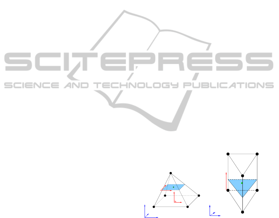
Figure 2: Determining parametric representation of an in-
terior point P(x,y,z) in: (a) a square pyramid: (s,t,u) three-
tuple parametric representation is used for points. With re-
spect to the quadrilateral slice P
0
000
P
0
100
P
0
110
P
0
010
containing
P being parallel to base face P
000
P
100
P
110
P
010
, u is the pa-
rameter in the z direction; (s,t) is the two-tuple paramet-
ric representation of the point in the slice, which degen-
erates to a single point at the apex P
001
. (b) a right tri-
angular prism: (α, β, γ,u) four-tuple parametric representa-
tion is used for points. With respect to the triangular slice,
P
0
1000
P
0
0100
P
0
0010
, containing P and the axial edges, namely,
P
1000
P
1001
, P
0100
P
0101
, and P
0010
P
0011
, u is the linear pa-
rameter along one of the three axial edges; (α, β, γ) gives
the barycentric coordinates of P in the slice.
ISOSURFACE EXTRACTION FROM HYBRID UNSTRUCTURED GRIDS CONTAINING PENTAHEDRAL
ELEMENTS
663
tor ˆn and its plane equation, Ax + By + Cz +
D
0
= 0, where ˆn = {A, B,C}
T
.
(b) At the apex P
001
,
D
1
= −(Ax
0
+ By
0
+Cz
0
).
(c) u(x, y, z) = −
Ax+By+Cz+D
0
D
1
−D
0
.
2. Using u, we determine the quadrilateral slice
P
0
000
P
0
100
P
0
110
P
0
010
containing P, and represent P
using bilinear interpolation on the slice using two-
tuple (s,t), determined using the three equations
implied by the three coordinates of a point, i.e.,
P = (1 − s)(1 − t)P
0
000
+
s(1 − t)P
0
100
+ stP
0
110
+ (1 − s)tP
0
010
.
4.1.2 Right Triangular Prisms
The interpolation function for a triangular prism is
given by the following algebraic expression with real
coefficients:
F(x,y, z) = C
0
+C
1
x +C
2
y +C
3
z +C
4
xz +C
5
yz
Any point in the cell can be represented paramet-
rically by using four parameters: (a) a parameter u
representing the position of a triangular slice contain-
ing the point, with respect to any of the three edges
not belonging to the triangular bases (referred to as
axial edges), and (b) three barycentric coordinates,
(α,β,γ), of the point in the triangular slice, as shown
in Figure 2(B). (u = 0) and (u = 1) represent the two
triangular bases, respectively, and the three quadrilat-
eral faces are represented by (α = 1), (β = 1), and
(γ = 1), respectively.
Let the cell contain vertices, P
1000
, P
0100
, P
0010
on one triangular face and P
1001
, P
0101
, P
0011
at the
other end. The function values at P
αβγu
, are given
by F
αβγu
and coordinates are (x
αβγu
,y
αβγu
,z
αβγu
). Ev-
ery point P(x, y, z) in space can be represented as
p(α,β, γ, u) with respect to the cell. Suppose the tri-
angular slice P
0
1000
P
0
0100
P
0
0010
containing P has its ver-
tices with parametric representation u with respect to
the axial edges. The function value at P, F(x, y, z) is
interpolated using the formula:
F(x,y, z) = f (α, β,γ, u)
=(1 − u)(F
1000
α + F
0100
β + F
0010
γ)
+ u(F
1001
α + F
0101
β + F
0011
γ)
(1)
For any point in the interior to or on the boundary
of the cell, 0.0 ≤ u,α, β,γ ≤ 1.0 and α + β + γ = 1.
Due to linear dependence of α, β, and γ, we can re-
duce the parametric representation to a three-tuple,
(α,β, u) to represent the set of linearly independent
variables. However, to maintain the ease of represen-
tation, we continue to refer to the four-tuple paramet-
ric representation (α, β,γ, u), in the interpolation func-
tion.
To determine (α, β, γ,u) for a given point P(x, y, z),
we perform the following steps:
1. The parameter u defines the triangular slice
(P
0
1000
P
0
0100
P
0
0010
) containing P.
P
0
1000
= P
1000
+ u(P
1001
− P
1000
)
P
0
0100
= P
0100
+ u(P
0101
− P
0100
)
P
0
0010
= P
0010
+ u(P
0011
− P
0010
)
If the two triangular bases are parallel, we obtain
u the same way as in the case of square pyramids.
We determine the following:
(a) For the base P
1000
P
0100
P
0010
, the normal vector
ˆn and its plane equation, Ax+By+Cz+D
0
= 0,
where ˆn = {A, B,C}
T
.
(b) For the opposite triangular face
P
1001
P
0101
P
0011
, the corresponding value
of D
1
using one of the three vertices in the face
as (x,y, z): D
1
= −(Ax + By +Cz).
(c) We determine the parameter
u(x,y, z) = −
Ax+By+Cz+D
0
D
1
−D
0
.
However, more generally, the value for u is the so-
lution of the cubic equation in u given by:
(P
0
1000
− P) · ((P
0
0100
− P) × (P
0
0010
− P)) = 0.
In the case of a right triangular prism, we get a
unique real value for u, which satisfies the condi-
tion 0.0 ≤ u ≤ 1.0.
2. Using u, we determine the triangular slice
(P
0
1000
P
0
0100
P
0
0010
) containing P, and determine the
barycentric coordinates (α, β, γ) of the point in the
triangle.
4.2 Look-up Tables
Just as in the marching cubes algorithm, we repre-
sent the cases of pentahedral cells using a bit-string
C0 C1
C2 C3
C4 C5
C0 C1
C2 C3
C4 C5
C6 C7
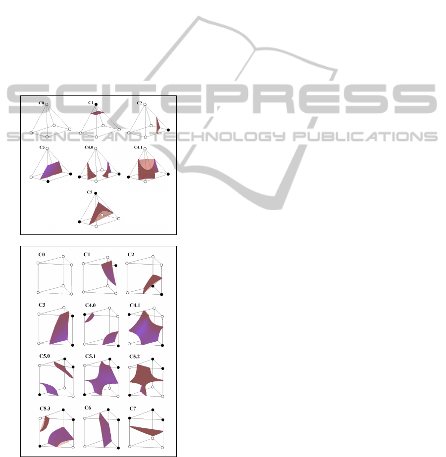
(a) (b)
Figure 3: Base configurations of a pentahedral element: (a)
Six of a square pyramid; (b) eight of a right triangular prism.
Black points and circles indicate vertices whose function
values are larger or smaller than the isosurface value, re-
spectively.
IVAPP 2012 - International Conference on Information Visualization Theory and Applications
664
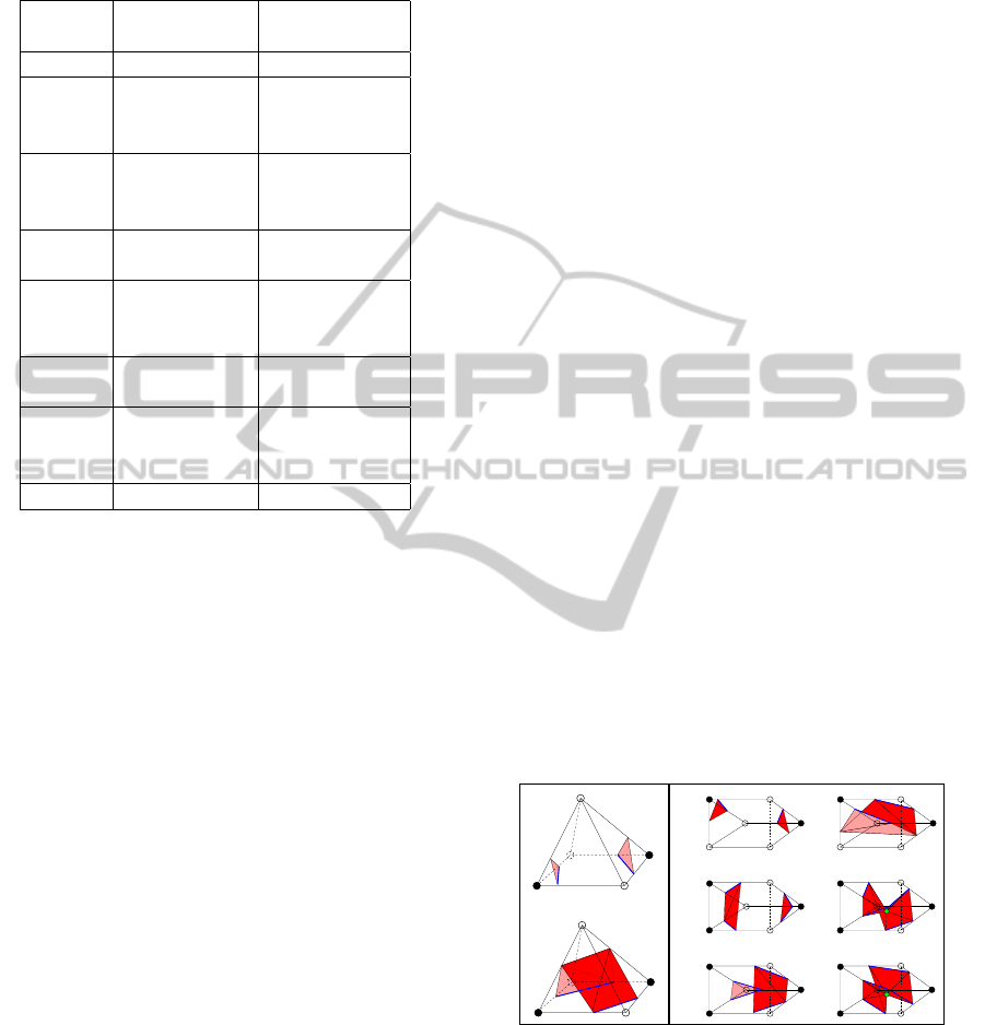
Table 1: Classification of all cases into base configurations
of a pentahedral element: six for square pyramid and eight
for triangular prism cells.
Config- Pyramid Prism
uration Cases Cases
0 0, 31 0, 63
1 1, 30 1, 2, 4, 8,
16, 31, 32, 47,
55, 59, 61, 62
2 2, 4, 8, 15, 3, 5, 6, 15,
16, 23, 27, 29 23, 24, 39, 40,
48, 57, 58, 60
3 6, 7, 12, 13, 9, 18, 27,
18, 19, 24, 25 36, 45, 54
4 10, 11, 20, 21 10, 12, 17, 20,
29, 30, 33, 34,
43, 46, 51, 53
5 3, 5, 9, 14, 14, 21, 28,
17, 22, 26, 28 35, 42, 49
6 - 11, 13, 19, 22,
25, 26, 37, 38,
41, 44, 50, 52
7 - 7, 56
where each bit corresponds to a specific vertex of the
cell. For a k-node cell, thus, there can be 2
k
cases.
However, these cases can be reduced to unique base
configurations using mapping based on mirroring, ro-
tation and complementation. Thus, 32 cases of square
pyramid reduce to six unique configurations; and 64
cases of right triangular prisms reduce to eight. Fig-
ure 3 shows the unique base configurations of both
cell types; and Table 1 classifies all cases according
to their respective base configurations.
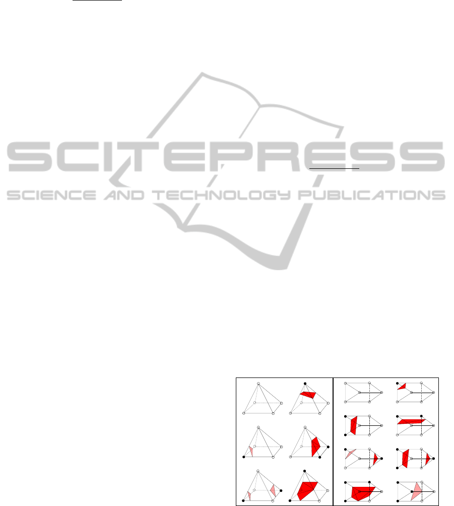
4.2.1 Resolving Ambiguities
Quadrilateral faces in the pentahedral cells can lead to
ambiguities which are resolved using the asymptotic
decider (Nielson and Hamann, 1991), as done in the
marching cubes algorithm. As shown in Figure 4(A),
configuration 4 of the square pyramidal cell contains a
single ambiguous face, ABCD. Subconfigurations 4.0
and 4.1 occur when ABCD is “separated” and “con-
nected”, respectively. As shown in Figure 4(B), con-
figurations 4 and 5 of the right triangular prismatic
cell have been resolved. Configuration 4 contains a
single ambiguous face, ABDC; while configuration 5
contains two, namely, ABDC and CDFE. Subconfig-
urations 4.0 and 4.1 occur when ABDC is separated
and connected, respectively. Subconfigurations of 5
occur with possibilities of ABDC and CDFE being
separated and connected. Thus, we have subconfig-
urations 5.0 and 5.3 with both faces being separated
and connected, respectively. 5.1 and 5.2 are comple-
mentary: in 5.1, ABDC is separated and CDFE is con-
nected; and in 5.2, vice versa.
In the prismatic cell, the configurations 5.1 and
5.2 require tangent points to obtain accurate topolog-
ical representation of the isosurface, as the isosurface
assumes the behavior of topological type A.2 (Lopes
and Brodlie, 2003). Generally, for configuration 5,
the tangent at the body saddle point of the isosur-
face will be parallel to the single non-ambiguous face,
hence, the tangent point coincides with the body sad-
dle point. The computation of body saddle points for
right triangular prisms is discussed in the Appendix.
The surfaces computed from our interpolation
models for all the configurations for both cell types
are shown in Figure 5.
5 DIRECT ISOSURFACE
EXTRACTION FROM HYBRID
MESHES
As explained in Section 3, for direct isosurface extrac-
tion from hybrid grids, we use the respective look-up
tables for each element type.
5.1 Gradient Approximation
Gradient interpolation is required for computing nor-
mal vectors which are used for lighting purposes dur-
ing rendering the isosurface. We implemented per-
C4.1
A B
CD
C4.0
C4.0
C5.0 C5.1
C4.1
C5.2C5.3
A
C
E
B
F
D
(a) (b)
Figure 4: Subconfigurations of pentahedral cells resolv-
ing ambiguities: Blue lines help to show if the ambigu-
ous face is connected or separated. (a) Square pyramidal
cells: In 4.0 and 4.1, ABCD is separated and connected,
respectively. (b) Right triangular prismatic cells: In 4.0
and 4.1, ABDC is separated and connected, respectively.
In 5.0 and 5.3, ABDC and CDFE are both separated and
connected, respectively; in 5.1 and 5.2, which are comple-
mentary, the isosurfaces require additional vertices, namely
the body saddle points, indicated by green vertices.
ISOSURFACE EXTRACTION FROM HYBRID UNSTRUCTURED GRIDS CONTAINING PENTAHEDRAL
ELEMENTS
665
vertex gradient approximation using a preprocessing
step. We use a least squares procedure (Anderson and
Bonhaus, 1994), which computes unweighted gradi-
ents in two-dimensional space by solving an over-
determined system of equation, which we extended to
the three-dimensional case using the equation: f
i
=
f
0
+ f
x
0
(x
i
− x
0
) + f
y
0
(y
i
− y
0
) + f
z
0
(z
i
− z
0
), where f
i
and f
0
are the values of the function f at points P
i
and
P
0
, and P
i
, for i = 1, 2,.. ., N have edges with P
0
. The
gradient at N
0
is
~
f
0
0
= ( f
x
0
, f
y
0
, f
z
0
). This leads to an
N × 3 system of equations:
∆x
1
∆y
1
∆z
1
∆x
2
∆y
2
∆z
2
.
.
.
.
.
.
.
.
.
∆x
N
∆y
N
∆z
N
f
x
0
f
y
0
f
z
0
=
f
1
− f
0
f
2
− f
0
.
.
.
f
N
− f
0
(a)
(b)
Figure 5: Isosurfaces, with topological considerations for:
(a) all seven configurations of the square pyramidal cells;
(b) all twelve configurations of the right triangular prismatic
cells.
For solving this over-determined system of equations,
we computed
r
ab
=
N
∑
i=1
(a
0
− a
i
)(b
0
− b
i
), where a, b ∈ {x, y,z}
r
xx
r
xy
r
xz
r
xy
r
yy
r
yz
r
xz
r
yz
r
zz
W
x
i
W
y
i
W
z
i
=
x
i
− x
0
y
i
− y
0
z
i
− z
0
We solved for the weights W
x
i
, W
y
i
and W
z
i
using
Cramer’s rule, and approximated the gradient using:
f
a
0
=
∑
N
i=1
W
a
i
( f
i
− f
0
), where a ∈ {x, y,z}.
6 RESULTS
We implemented our algorithm on a visualization
cluster, Colt, at TACC, with the following specifica-
tions: 2 Intel Xeon quad core E5440 processors (8
cores total), 16 GB of RAM, nVidia Quadro FX5800
graphics card with 4 GB memory.
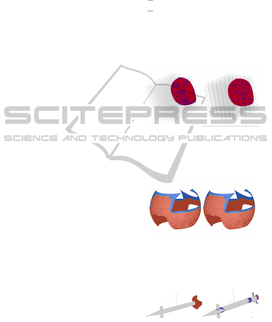
We tested our method for a synthetic dataset con-
sisting of 1,331 nodes, containing all prisms; and de-
composed it to a purely tetrahedral grid. We extracted
isosurfaces from the original prism and the tetrahe-
dralized grids, as shown in Figure 6. We used a blue-
to-red colormap to map the quality measure of the tri-
angles from 0 to 1, for which we used the incircle
to circumcircle radius ratio (P
´
ebay and Baker, 2003).
The time taken to render the isosurfaces in the prism
grid and tetrahedral grid are 0.01 and 0.03 seconds,
respectively, for the value 0.305.
We applied our method to hybrid grids defining
(a) a wind-tunnel model from NASA, shown in Fig-
ure 7, with 442,368 hexahedral, 721,413 tetrahedral,
and 13,824 pyramidal elements; (b) a missile, shown
in Figure 8, with 6,378,506 nodes, 2,479,668 tetra-
hedra, 17,691 pyramids and 4,207,433 prisms. The
results of our direct isosurface extraction method are
tabulated in Table 2. Our timing measurements for
reading the file and preprocessing gradients did not
show any improvement compared to our experiments
using ParaView, and hence, we have not included
them here.
7 CONCLUSIONS
Figures 6, 7 and 8 show that our method generated re-
sults comparable to those from standard methods. As
expected, our method generated fewer triangles com-
pared to applying the marching tetrahedra algorithm
IVAPP 2012 - International Conference on Information Visualization Theory and Applications
666
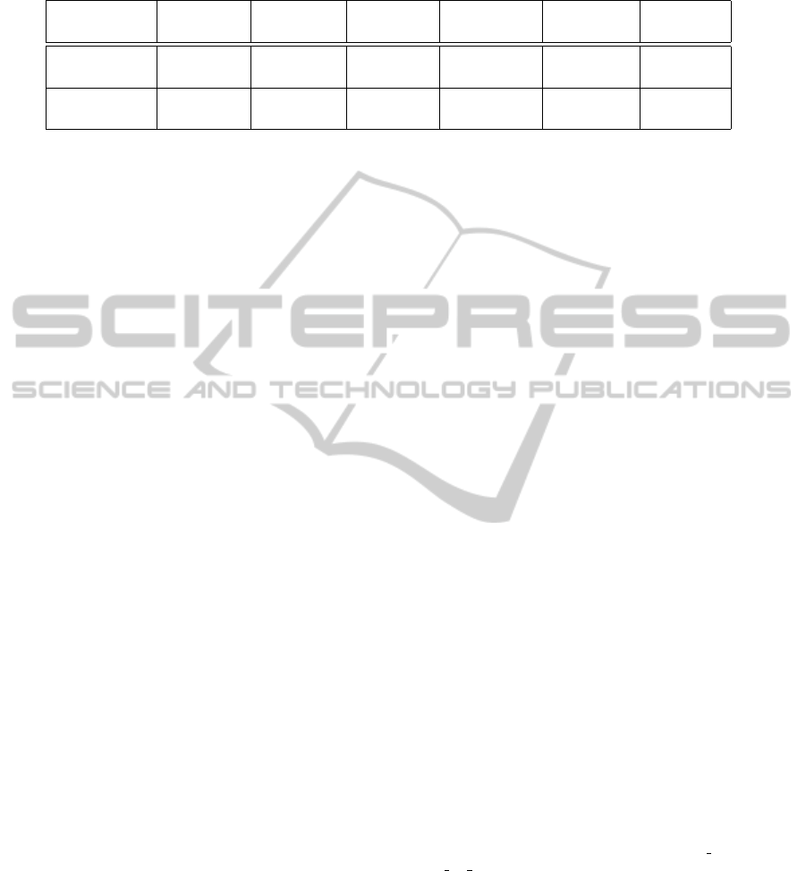
Table 2: Results of our isosurface extraction algorithm: #Tri-tetra represents the number of triangles rendered using look-
up table for tetrahedra, #Tri-pyram that for square pyramids, #Tri-prism that for triangular prisms, and #Tri-hexa that for
hexahedra.
Dataset Isosurface Extraction #Tri-tetra #Tri-pyram #Tri-prism #Tri-hexa
value time (in s)
Wind-tunnel 13.0464 0.95 29,241 586 0 30,226
dataset 12.1772 0.77 25,117 390 0 5,198
Missile 1.167 180.26 1,446,544 4,316 352,177 0
dataset 0.62 93.6 236,384 4,570 700,971 0
on a tetrahedralized grid owing to the lower number
of elements. However, our method being a marching
method does not always produce good quality trian-
gles in the mesh, as can be seen in Figure 6. Owing
to lower triangle count, our method performs better
in regions with lower surface curvature and worse in
regions with higher surface curvature, in comparison
to the marching tetrahedra method on the tetrahedral-
ized grid. Our method is comparably computationally
efficient, especially for larger datasets. The gradient
computation requires O(n) time for n being the num-
ber of nodes in the dataset. The gradient estimation
step needs to be performed just once as a preprocess-
ing step, which makes real-time generation of smooth
isosurfaces efficient. However, in case of the missile
dataset, we did not see a significant improvement in
performance owing to the fact that dataset consists of
85% tetrahedra.
Furthermore, we have covered all the ambiguous
configurations possible that can occur for pentahedral
elements, i.e., our look-up tables are complete. We
have found that computation of body saddle points in
a triangular prismatic element is similar to that of the
hexahedron.
Our method can be further enhanced with the op-
timization strategies which are used in the marching
cubes method.
ACKNOWLEDGEMENTS
We are grateful to: (a) Dr. David Marcum of Missis-
sippi State University, and to Dr. Benjamin Kirk of
NASA/JSC for sharing the missile and wind-tunnel
datasets, respectively; (b) Dr. John W. Peterson of
TACC for helping with using GMV and for providing
experimental FEM datasets; (c) TeraGrid Resource
Provider Grant as well as IIIT-Bangalore for support;
(d) members of the Visualization Group in TACC and
IIIT-Bangalore, especially, Prof. K. V. Dinesha, and
Mr. Pratap J. Rao.
REFERENCES
Anderson, W. K. and Bonhaus, D. L. (1994). An Implicit
Upwind Algorithm for Computing Turbulent Flows
on Unstructured Grids. Comput. Fluids, 23:1–21.
Bhaniramka, P., Wenger, R., and Crawfis, R. (2004). Iso-
surface Construction in Any Dimension Using Con-
vex Hulls. IEEE Transactions on Visualization and
Computer Graphics, 10:130–141.
Carr, H., Moller, T., and Snoeyink, J. (2006). Artifacts
Caused by Simplicial Subdivision. IEEE Transactions
on Visualization and Computer Graphics, 12:231–
242.
Gallagher, R. S. and Nagtegaal, J. C. (1989). An Efficient
3-D Visualization Technique for Finite Element Mod-
els and Other Coarse Volumes. SIGGRAPH Comput.
Graph., 23:185–194.
Lasser, D. (1985). Bernstein-B
´
ezier Representation of
Volumes. Computer Aided Geometric Design, 2(1-
3):145–149.
Lopes, A. and Brodlie, K. (2003). Improving the Robust-
ness and Accuracy of the Marching Cubes Algorithm
for Isosurfacing. IEEE Transactions on Visualization
and Computer Graphics, 9:16–29.
Lorensen, W. E. and Cline, H. E. (1987). Marching
Cubes: A High Resolution 3D Surface Construction
Algorithm. In Proceedings of ACM conference on
Computer graphics and interactive techniques - SIG-
GRAPH 1987, pages 163–169. ACM Press.
Montani, C., Scateni, R., and Scopigno, R. (1994). A Mod-
ified Look-up Table for Implicit Disambiguation of
Marching Cubes. The Visual Computer, 10(6):353–
355.
Moreland, K. (2011). ParaView User’s Guide v3.12.
Kitware Inc., Sandia National Laboratory, CSimSoft,
http://www.itk.org/Wiki/ParaView/Users Guide/Table
Of Contents.
Muigg, P., Hadwiger, M., Doleisch, H., and Hauser, H.
(2007). Scalable Hybrid Unstructured and Structured
Grid Raycasting. IEEE Transactions on Visualization
and Computer Graphics, 13(6):1592–1599.
Newman, T. S. and Yi, H. (2006). A Survey of the Marching
Cubes Algorithm. Computers & Graphics, 30(5):854–
879.
Nielson, G. M. (2003). On Marching Cubes. IEEE
Transactions on Visualization and Computer Graph-
ics, 9(3):283–297.
ISOSURFACE EXTRACTION FROM HYBRID UNSTRUCTURED GRIDS CONTAINING PENTAHEDRAL
ELEMENTS
667
Nielson, G. M. and Hamann, B. (1991). The Asymp-
totic Decider: Resolving the Ambiguity in Marching
Cubes. In Nielson, G. M. and Rosenblum, L. J., ed-
itors, Proceedings of IEEE Visualization 1991, pages
83–91. IEEE Computer Society Press.
Ortega, F. A. (2008). Personal correspondence via e-
mail with chief developer of GMV. http://www-
xdiv.lanl.gov/XCM/gmv/GMVHome.html.
Ortega, F. A. (2011). GMV 4.5 General Mesh Viewer User’s
Guide. Los Alamos National Laboratory, CPFD Soft-
ware, http://www.generalmeshviewer.com/.
P
´
ebay, P. P. and Baker, T. J. (2003). Analysis of Trian-
gle Quality Measures. Mathematics of Computation,
72:1817–1839.
Takahashi, T., Mekada, Y., Murase, H., and Yonekura, T.
(2004). High Quality Isosurface Generation from
Volumetric Data and Its Application to Visualization
of Medical CT Data. In Proceedings of the Pat-
tern Recognition, 17th International Conference on
(ICPR’04) Volume 3 - Volume 03, ICPR ’04, pages
734–737, Washington, DC, USA. IEEE Computer So-
ciety.
Weber, G. H., Kreylos, O., Ligocki, T. J., Shalf, J., Hagen,
H., Hamann, B., Joy, K. I., and Ma, K.-L. (2001).
High-quality Volume Rendering of Adaptive Mesh
Refinement Data. In Proceedings of the Vision Mod-
eling and Visualization Conference 2001, VMV ’01,
pages 121–128. Aka GmbH.
Weber, G. H., Kreylos, O., Ligocki, T. J., Shalf, J. M., Ha-
gen, H., Hamann, B., and Joy, K. (2003). Extraction
of Crack-Free Isosurfaces from Adaptive Mesh Refine-
ment Data, pages 19–40. Springer-Verlag, Heidel-
berg, Germany.
Williams, P. L., Max, N. L., and Stein, C. M. (1998). A
High Accuracy Volume Renderer For Unstructured
Data. IEEE Transactions on Visualization and Com-
puter Graphics, 4:37–54.
APPENDIX
Computation of Body Saddle Points in
Triangular Prisms for Configurations 5
As explained in Section 4.1.2, the combined inter-
polation model uses three linearly independent vari-
ables, (α, β, u). The quadrilateral faces of the
prism can be represented as either (α = 1), (β = 1),
or (γ = 1), respectively. In Figure 2(B), the face
P
0100
P
0101
P
0011
P
0010
, corresponds to (α = 1). Here,
we describe the computations for the case where (α =
1) is the non-ambiguous face, which can be appropri-
ately extended to the cases when (β = 1) or (γ = 1) is
the non-ambiguous case. The body saddle point oc-
curs at a point where, for an isosurface of value I, the
following conditions are satisfied:
1. F = F(x, y,z) − I = f (α
τ
,β
τ
,γ
τ
,u
τ
) − I = 0
2.
∂F
∂u
= F
u
= 0
3.
∂F
∂α
= F
α
= 0
We use the following notations for simplifying alge-
braic expressions:
D
(α,0)
= F
1000
− F
0010
;D
(α,1)
= F
1001
− F
0011
;
D
α
= D
(α,0)
− D
(α,1)
We use similar notations in the case of β: D
(β,0)
,
(a) (b)
Figure 6: Isosurface for same value extracted from a grid
consisting of 1331 nodes, with: (a) 2000 triangular pris-
matic elements; and (b) 5220 tetrahedral cells. The isosur-
face consists of: (a) 478 triangles, and (b) 888 triangles.
The color of triangles shows its quality mapped from worse
to better, corresponding to blue-to-red colormap.
(a) (b)
Figure 7: Isosurfaces of function ln(c k~x − ~x
0
k
2
), for con-
stants c and ~x
0
, in hybrid grid of a wind-tunnel model for
values: (a) 13.0464 and (b) 12.1772. The red surface is
generated by using look-up table for tetrahedra, the blue
surface by that for hexahedra and green surface by that for
pyramids.
(a) (b)
Figure 8: Isosurface from the missile dataset for density in
compressible flow for values (a) 1.167 and (b) 0.62. The
blue surface is generated using our new look-up tables for
prisms and pyramids, and the red one is generated by that
for tetrahedra.
IVAPP 2012 - International Conference on Information Visualization Theory and Applications
668

D
(β,1)
, and D
β
.
Differentiating F with respect to α,
F
α
= (1 − u
τ
)D
(α,0)
+ u
τ
D
(α,1)
(2)
After applying the condition F
α
= 0 in Equation 2 and
simplifying, one obtains:
1 − u
τ
u
τ
=
D
(α,1)
D
(α,0)
⇒ u
τ
=
D
(α,0)
D
α
(3)
On substituting for γ
τ
= (1 − α
τ
− β
τ
) and u
τ
from
Equation 3, in Equation 1, the coefficient of α reduces
to 0. Hence, on applying the condition F = 0, one
obtains:
β
τ
=
(D
α
· I + F
1001
· F
0010
− F
1000
· F
0011
)
(D
(α,0)
· D
(β,1)
− D
(α,1)
· D
(β,0)
)
(4)
Differentiating F with respect to u,
F
u
= − (F
1000
α
τ
+ F
0100
β
τ
+ F
0010
γ
τ
)
+ (F
1001
α
τ
+ F
0101
β
τ
+ F
0011
γ
τ
)
(5)
After applying the condition F
u
= 0 in Equation 5 and
γ
τ
= (1 − α
τ
− β
τ
); and simplifying using β
τ
from
Equation 4, one obtains:
α
τ
=
(F
0011
− F
0010
)
D
α
−
D
β
D
α
· β
τ
(6)
Using the interpolation model from Equation 1, the
values for parameters from Equations 3, 4, and 6, and
substituting γ
τ
= (1 − α
τ
− β
τ
), the tangent point is
computed as:
P
τ
(x,y,z) = p(α
τ
,β
τ
,γ
τ
,u
τ
)
=(1 − u
τ
)(α
τ
P
1000
+ β
τ
P
0100
+ γ
τ
P
0010
)
+ u
τ
(α
τ
P
1001
+ β
τ
P
0101
+ γ
τ
P
0011
)
ISOSURFACE EXTRACTION FROM HYBRID UNSTRUCTURED GRIDS CONTAINING PENTAHEDRAL
ELEMENTS
669
