
A GENERAL MOTION REPRESENTATION
Exploring the Intrinsic Viewpoint of a Motion
Gutemberg Guerra-Filho
Department of Computer Science and Engineering, University of Texas at Arlington,
500 UTA Blvd, Arlington, TX, U.S.A.
Keywords: Motion Capture Format, Motion Representation, Pre-rotation Transformation.
Abstract: We propose a novel motion representation, named General Motion Representation (GMR), which explicitly
contains the absolute world coordinates of the meaningful joints, while still specifying every other joint with
rotational data relative to their respective parent joints. More specifically, our representation supports
multiple roots where any joint can be a root due to the use of a novel pre-rotation format for the construction
of local transformation matrices. Hence, our general motion representation allows for all intermediate data
structures between fully rotational and fully translational data. The use of multiple roots also implies the
representation of partial motion considering a subset of joints. We introduce the general motion
representation to consider multiple roots with the support of three operations (shift root, split skeleton tree,
and join skeleton trees). These operations allow reduced skeletal complexity because of the application of
pre-rotation local transformation matrices which eliminates the requirement for dummy joints. We also
present procedures to convert from raw marker data or post-rotation formats. We demonstrate the highly
efficient computation of per-frame joint positions and orientations. Our experimental results show that
GMR outperforms traditional motion formats in both speed and flexibility. At the full translational
configuration, GMR is around seven times faster than bvh.
1 INTRODUCTION
A fundamental issue for problems involving the
synthesis and analysis of human movement is the
representation for three-dimensional human motion.
With regards to human motion representation,
motion capture records the skeletal motion of a
human body by reconstructing the evolution of the
angles of articulated joints in a skeleton model.
In this paper, we address the problem of finding
a skeletal motion representation that allows the
explicit description of only the essential joints for a
particular motion in terms of world coordinates
while the non-essential joints are described by
rotational data inferred according to a skeleton
model. Formally, given a set M of three-dimensional
points representing the Cartesian location of markers
placed on the skin of the human subject at each time
frame during motion capture; a skeleton model S(G,
R) that consists of an adjacency graph G (where
nodes represent articulated body parts and edges
represent joints connecting these body parts) and a
relation R between markers and body parts stating
which markers belong to each body part; and a set E
of essential joints; we want to find a motion
representation such that essential joints are described
by 3D Cartesian points and non-essential joints are
described by rotational angles. Our main objective is
to find algorithms to construct this generalized
motion representation in order to consider any
possible set of essential joints. The motion
representation is obtained either from marker data
(as stated above) or from other existing
representations (e.g., single-root motion capture
data). A secondary objective is to develop the
necessary operations to allow the transformation of
the motion representation from any current set of
essential joints E
o
to any other target set of essential
joints E
t
.
We propose a novel motion representation,
named General Motion Representation (GMR),
which supports all combinations of root joint
configurations (i.e., any joint can be a root and
multiple roots are supported), highly efficient
computation of per-frame joint positions and
orientations, and partial motion representations. This
is only possible because we propose a more general
method of constructing transformation matrices
347
Guerra-Filho G..
A GENERAL MOTION REPRESENTATION - Exploring the Intrinsic Viewpoint of a Motion.
DOI: 10.5220/0003855303470352
In Proceedings of the International Conference on Computer Graphics Theory and Applications (GRAPP-2012), pages 347-352
ISBN: 978-989-8565-02-0
Copyright
c
2012 SCITEPRESS (Science and Technology Publications, Lda.)

using pre-rotation transformations instead of the
standard post-rotation transformations in the bvh and
asf/amc formats. The main contributions of this
paper are: (1) a general motion representation that
considers multiple roots, (2) the introduction of three
operations to support this data structure (shift root,
split skeleton tree, and join skeleton trees), (3) the
procedures to convert from raw marker data or post-
rotation formats (e.g., bvh and asf/amc) to our pre-
rotation format, and (4) experimental results
showing the time and space performance of our new
motion representation. At the full translational
configuration, GMR is around seven times faster
than bvh. Our experiments are centered on the
rendering of joint positions. However, similar
experiments based on the computation of joint
coordinate frames are equivalent to ours since joint
coordinate frames are necessary to the rendering of
joint positions.
The remaining of this paper is organized as
follows. Section 2 presents a review on work related
to skeletal motion representation. Section 3
discusses the differences between existing post-
rotation formats (bvh and asf/amc) and our pre-
rotation format. Section 4 presents the General
Motion representation and its three operations.
Section 5 describes the generation of GMR from raw
marker data or from a post-rotation format. Section 5
summarizes the experimental results on time and
space performance comparing the bvh format and
our GMR representation.
2 RELATED WORK
Existing motion capture formats, such as bvh and
asf/amc, lack modeling flexibility by providing a
single skeletal root joint for all motions. These
formats implicitly restrict the choice of the root joint
by requiring that the root’s children behave as a rigid
body (i.e., a single rigid motion for all children of a
joint). This restriction is a consequence of the way
that local transformation matrices are composed to
derive global coordinates for joints according to
these formats. A formal proof of this fact is avoided
here due to a lack of space. However, this rigid body
constraint applies actually to any joint having more
than one child in the skeleton tree. For this reason,
artificial dummy joints are necessary to model
independent motion for multiple children of a single
joint. A simple inspection of existing motion files at
joints with more than one child, in bvh format for
example, suffices to verify the need for dummy
joints to allow independently moving joints with a
single parent. This is a significant drawback of state-
of-art motion representations by creating additional
time and space requirements and algorithmic
complications to handle exceptions and degeneracy
in motion-based techniques.
In the area of skeletal motion representations,
Brostow et al. (2004) introduced the concept of
spines in order to discover an articulated creature’s
skeleton directly from time-varying volumetric
structures. Coleman et al. (2008) introduce
staggered poses as a generalization of poses in
traditional key-framed motion. This generalization
allows for explicitly encoded timing refinements,
where each refinement is slightly offset in time. The
relationships between these timing refinements
determine how the character will pass through the
extreme values of the pose and are important for
modeling believable propagation of force and
intention through a body. Kulpa et al. (2005) created
a morphology-independent representation of
motions for interactive human-like animation. Their
aim was to enable real-time adaptive animation
using a sparse motion capture database. Unlike their
approach, our aim was to create a data structure with
the flexibility to provide multiple root joints for the
same motion.
Research has been done in the area of modeling
figures with complex skeleto-muscular relationships
based on human anatomy (Scheeper et al., 1997).
Complex motion control algorithms, which have
been developed for primitive articulated models
better suit robot-like characters than they do human
figures (Magnenat-Thalmann and Thalmann, 1991).
GMR-based skeletal models more closely resemble
actual human skeletons than post-rotation-based
skeletal models because GMR does not require
dummy skeletal joints.
3 POST-ROTATION AND
PRE-ROTATION FORMATS
Existing motion representations compose each
joint’s local transformation matrix in a post-rotation
order, which forces the children of each joint to
behave as a rigid body. Existing post-rotation
formats overcome this restriction through the use of
artificial dummy joints which corresponds to
additional time and space requirements. For
example, when the pelvis is the root joint, the left
hip joint, right hip joint, and lower back joint (the
pelvis joint’s children in the skeleton tree) cannot
move independently of one another. More
importantly, it is impossible to make any desired
GRAPP 2012 - International Conference on Computer Graphics Theory and Applications
348

joint the skeletal root when using a post-rotation
format. For example, if the neck joint were to be the
root, then the head, left shoulder, and right shoulder
would not be able to move independently unless a
cumbersome scheme with artificial dummy joints is
used, which is clearly a problem.
To remedy the limitations of post-rotation
formats, GMR composes each joint’s local
transformation matrix in a pre-rotation order that
allows for any joint to be a root. We describe the
post-rotation and pre-rotation concepts below.
3.1 Global Transformation Matrices
Here we describe the general approach for
composing a joint’s global transformation matrix
from local transformation matrices. Let d indicate
the depth of joint j, p(j) indicate the parent of joint j,
and p
k
(j) indicate the kth ancestor of joint j. Note that
the root joint is denoted by p
d
(j). Let L
j
and M
j
indicate the local and global transformation matrices
for joint j, respectively. Let G
r
indicate the
transformation matrix with just the global offset of
the skeleton. Then,
M
j
=
G
r
L
p
d
( j)
...L
p
2
( j)
L
p( j)
L
j
.
(1)
Let P
j
indicate the 3-dimensional, homogeneous
position of joint j described by multiplying M
j
with
the origin of the world coordinate system:
P
j
= M
j
0001
[]
T
.
Also, let
I
indicate the 3x3 identity matrix, and
o indicate the zero column-vector,
o = 000
[]
T
.
3.2 Post-rotation Order
The bvh and asf/amc formats use the post-rotation
order of composing local transformation matrices, as
shown in the following equation,
⎥
⎦
⎤
⎢
⎣
⎡
=
⎥
⎦
⎤
⎢
⎣
⎡
⎥
⎦
⎤
⎢
⎣
⎡
=
111
T
jj
T
j
T
j
j
o
tR
o
oR
o
tI
L
,
(2)
where R
j
and t
j
are the rotation matrix and the offset
for joint j.
From Equations (1) and (2), note that the rotation
R
j
is not applied to the joint j. Consider the root r of
a skeleton tree, the root’s rotation is the only rotation
that is applied to its children, which means that each
of the root’s immediate children cannot rotate
independently of one another. Hence, the root and its
immediate children behave as a rigid body. This
constraint is valid for any joint with more than one
child in the skeleton tree.
This behavior limits the flexibility of all post-
rotation formats because only certain joints can be
roots. That is, any joint with more than a single
child, where its immediate children do not behave as
a rigid body, cannot be a root. For example, the neck
joint cannot be a root.
3.3 Pre-rotation Order
The pre-rotation order of composing local
transformation matrices is shown in the following
equation,
⎥
⎦
⎤
⎢
⎣
⎡
=
⎥
⎦
⎤
⎢
⎣
⎡
⎥
⎦
⎤
⎢
⎣
⎡
=
111
T
jjj
T
j
T
j
j
o
tRR
o
tI
o
oR
L
,
(3)
where R
j
and t
j
are defined as in the post-rotation
order. Equation (3) removes the restriction that a
root and its children must behave as a rigid body.
Intuitively, GMR gains this flexibility because each
joint possesses its own independent rotation that is
applied to both its children and itself.
4 THE GENERAL MOTION
REPRESENTATION
The GMR format is structurally similar to post-
rotation formats. A GMR file begins with a joint-
based skeleton specification, with frame motion data
following after. Each joint specifies a static offset
from its parent joint, a list of required rotation
channels (x-rotation, y-rotation, z-rotation), and a list
of optional translation channels (x-translation, y-
translation, z-translation). The order of the rotation
channels specifies the order in which the rotation
matrix should be composed.
4.1 GMR Operations
GMR has three basic operations that allow the
conversion of a motion from a fully rotational
representation to a fully translational representation,
and all representations in between. We present the
correctness proof for each operation in the
supplemental material.
Now, we need a way to differentiate between
symbols before and after one of the three GMR
operations is applied. Let every symbol X
j
indicate a
value before an operation is applied, and every
symbol X
j
’
indicate a value after an operation is
A GENERAL MOTION REPRESENTATION - Exploring the Intrinsic Viewpoint of a Motion
349
applied, where X is a rotation matrix, a translation
vector, a local transformation matrix, or a global
transformation matrix.
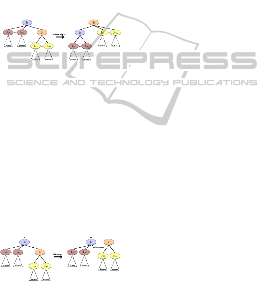
4.1.1 Shift Root Operation
The shift root operation is essentially a rotation of
the skeleton tree, meaning that it swaps the existing
root and one of its immediate children (see Figure
1). The repeated application of this operation allows
for shifting the root to any desired joint in the
skeleton tree.
Figure 1: The skeleton tree before and after the shift root
operation.
Using the notation defined in Section 3.2, we
specify the solution for the shift root operation
below. The following values should be recomputed
for each frame of the motion:
G
0
'
= R
0
R
1
t
1
+ t
0
,
R
1
'
= R
0
,
t
1
'
= o
,
R
0
'
= R
1
,
t
0
'
=−t
1
,
R
0i
'
= R
1
−1
R
0i
t
0i
'
= t
0i
R
1 j
'
= R
1
R
1 j
t
1 j
'
= t
1 j
4.1.2 Split Tree Operation
The split tree operation creates an additional root by
promoting an arbitrary joint to root status (see
Figure 2). Repeated applications of this operation
allow the conversion to a fully translational
representation. That is, this operation allows for a
representation where all joints are roots with 3D
Cartesian coordinates. Intuitively, a skeleton with n
joints may be represented as a single tree with n
joints or as a forest with n trees with a single joint.
Figure 2: The skeleton trees before and after the split tree
operation.
Let J
1
be the joint to promote to root status and J
0
be
the parent of J
1
. J
0
may or may not have a parent
joint. Note that the original tree structure is
preserved by a “soft” link from J
1
to its original
parent, J
0
. This link is necessary in order to undo
this split tree operation in the join tree operation
described next.
The global transformation matrix, M
1
, for J
1
before the split operation is
⎥
⎦
⎤
⎢
⎣
⎡
==
1
...
101
T
ss
rr
o
tR
LLLGM
,
(4)
where G
r
is the transformation matrix with the
global offset of the skeleton, L
r
is the local
transformation matrix for the root joint, R
s
is the
rotation matrix associated with M
1
, and t
s
is the
translation vector associated with M
1
. The
calculation of J
1
’s global transformation matrix
changes after promoting J
1
to root status, so
'
1
'
1
'
1
LGM =
.
(5)
However, the global transformation matrix M
1
’
must be equal to M
1
, so that we avoid changing the
local transformation matrix for each child of J
1
. This
allows us to set Equation (4) equal to Equation (5):
⎥
⎦
⎤
⎢
⎣
⎡
==
1
'
1
'
1
'
1
T
ss
o
tR
LGM
.
(6)
Factoring Equation (6) and using the notation
defined in Section 3.2, we specify the solution for
the split tree operation. Note that, before the split, J
1
did not possess a global translation, but after the
split, it does. The following values should be
recomputed for each frame of the motion:
R
1
'
= R
s
,
t
1
'
= o
T
,
G
1
=
It
s
o
T
1
⎡
⎣
⎢
⎤
⎦
⎥
.
4.1.3 Join Trees Operation
The join trees operation is the inverse of the split
tree operation. Where the split tree operation
promotes an arbitrary joint to root status, the join
trees operation demotes a root to a non-root joint
status (see Figure 3). This operation fails if applied
to the last remaining root, which is intuitively
correct because a skeleton cannot have zero roots.
GRAPP 2012 - International Conference on Computer Graphics Theory and Applications
350
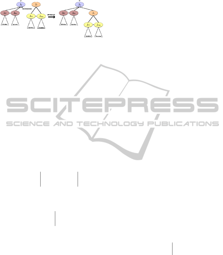
Figure 3: The skeleton trees before and after the join tree
operation.
Let J
1
be the joint to demote and J
0
be the
original parent of J
1
before a split operation. J
0
may
or may not have a parent joint. The global
transformation matrix M
0
for J
0
is
00
...LLGM
rr
=
(7)
From the solution to the split operation, we know
that
M
1
= M
1
'
. Also, applying the concept that a
joint’s global transformation matrix may be
constructed incrementally by multiplying the parent
joint’s global transformation matrix with the current
joint’s local transformation matrix, we have,
M
1
=
M
0
L
1
. Moreover, since
M
1
= M
1
'
, we have,
'
110
MLM =
.
L
1
is the matrix that we are solving for to undo
the effects of the split operation. Solving for L
1
, we
have,
L
1
= M
0
−1
M
1
'
. Furthermore, we make the
following definitions:
⎥
⎦
⎤
⎢
⎣
⎡
=
1
0
T
pp
o
tR
M
,
⎥
⎦
⎤
⎢
⎣
⎡
=
1
'
1
T
ss
o
tR
M
.
Applying the pre-rotation form of constructing
local transformation matrices from Equation (3), we
have,
⎥
⎦
⎤
⎢
⎣
⎡
=
1
111
1
T
o
tRR
L
.
Now, we specify the final solution to the join
trees operation. The following values should be
recomputed for each frame of the motion:
R
1
= R
p
−
1
R
s
,
t
1
= R
s
−1
(t
s
− t
p
)
.
5 GMR GENERATION
Ideally, GMR should be generated directly from
marker-data obtained in the motion capture process.
In this case, GMR will use the simplest, most
intuitive skeleton hierarchy possible, avoiding the
use of dummy joints. The conversion from post-
rotation formats, such as bvh and asf/amc is
possible, but preserves undesirable artifacts of the
post-rotation formats, such as the dummy joints.
5.1 From Marker Data
To convert directly from raw marker data to GMR,
first we have to find the global transformations for
the parent bone’s coordinate system and the child
bone’s coordinate system. If we let M
c
represent the
global transformation for the child bone and let M
p(c)
represent the global transformation for the parent
bone, then to compute the incremental
transformation from the parent coordinate system to
the child coordinate system we construct the
following equation,
ccpc
LMM
)(
=
.
In the above equation,
L
c
is the local
transformation matrix for the child bone. The
derivation of
L
c
is nearly identical to the derivation
of the solution for the GMR join trees operation and
has been omitted for the sake of brevity.
5.2 From a Post-rotation Order
Representation
It is also possible to convert directly from a post-
rotation order format, but doing so preserves
undesirable features of the original formats. For
example, a direct conversion from bvh to GMR
preserves all joints, even the joints that are no longer
required, such as the dummy joints contained in the
original bvh format. An improved conversion
method should automatically detect and remove
dummy joints before creating the GMR skeleton.
However, here we include the direct conversion
method.
Let
M
r
be the root’s global transformation
matrix. We define these symbols as,
⎥
⎦
⎤
⎢
⎣
⎡
=
1
T
rr
r
o
tR
M
.
Now, let R
p(j)
indicate the rotation for the parent
of node j before conversion, where j is an internal or
leaf node. For the sake of brevity, we only include
the solution,
IR
r
=
'
,
jj
tt =
'
,
)(
'
jpj
RR =
.
A GENERAL MOTION REPRESENTATION - Exploring the Intrinsic Viewpoint of a Motion
351
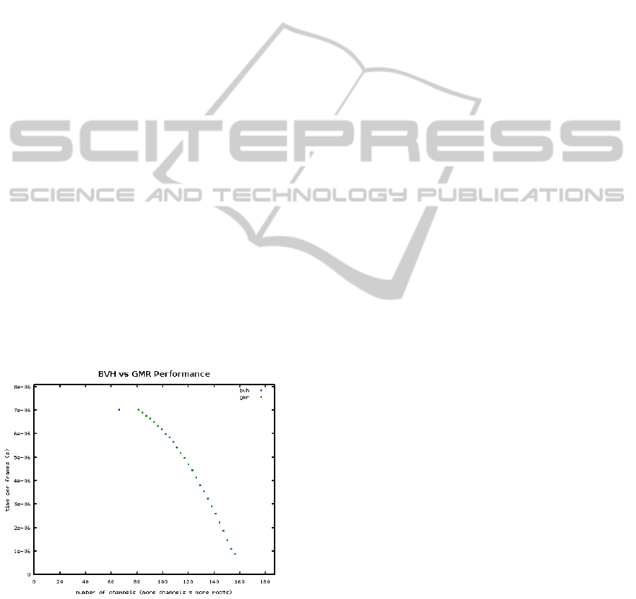
6 EXPERIMENTAL RESULTS
We tested the time and space performance of bvh
and GMR. We constructed an experiment that
computes the position of each joint for each frame of
motion. Our motion dataset consisted of 37 distinct
bvh motion capture files with 14.223 total minutes
of motion capture data (over 100,000 frames at 120
frames-per-second). We converted each bvh file to
the GMR format, where we tested GMR
performance using an optimized rendering loop that
took advantage of translational information in root
nodes. In the best case, GMR performs around 7
times faster than bvh. The results are summarized by
the graph in Figure 4. Although the time cost is a
single microsecond per frame in our experiments,
this speed up is significant especially in the context
of applications where very limited computation
power is available such as gaming and humanoid
robotics.
The left-most GMR point on the graph contains
one single root, while the right-most GMR point on
the graph contains 26 roots. For this experiment, we
define a GMR configuration C
k
as a GMR
containing k roots, for k = 1, …, 26. We constructed
ten GMR instances C
k
for each k by selecting
random sets of k joints as roots, in order to ensure
fairness and prevent artificially inflated performance
results. We then recorded the performance of each
instance. To compute the data points on the graph
above, we averaged the recorded times for GMR
configurations with matching numbers of roots.
Figure 4: Performance of GMR configurations compared
with BVH.
7 CONCLUSIONS
We introduced the general motion representation to
consider multiple roots with the support of three
operations (shift root, split skeleton tree, and join
skeleton trees). These operations allow reduced
skeletal complexity because of the application of
pre-rotation local transformation matrices which
eliminates the requirement for dummy joints. We
also present procedures to convert from raw marker
data or post-rotation formats.
We also demonstrate the highly efficient
computation of per-frame joint positions and
orientations. Our experimental results show that
GMR outperforms traditional motion formats in both
speed and flexibility. At the full translational
configuration, GMR is around seven times faster
than bvh. These benefits make GMR a good
candidate for computationally intensive, time-
sensitive tasks such as real-time gaming
applications. With respect to alternate viewpoints,
GMR also opens many avenues of research that
were once difficult to explore. Additionally, GMR
retains the familiarity and simplicity of expression of
the BVH file format.
REFERENCES
Brostow, G., Essa, I., Steedly, D., Kwatra, V., 2004. Novel
skeletal representation for articulated creatures.
Lecture Notes in Computer Science, vol. 3023, pp.
66-78.
Coleman, P., Bibliowicz, J., Singh, K., Gleicher, M., 2008.
Staggered poses: A character motion representation for
detail-preserving editing of pose and coordinated
timing. In Symposium on Computer Animation, pp.
137-146.
Kulpa, R., Multon, F., Arnaldi, B., 2005. Morphology-
independent representation of motions for interactive
human-like animation. Computer Graphics Forum,
vol. 24, pp. 343-351.
Magnenat-Thalmann, N., Thalmann, D., 1991. Complex
models for animating synthetic actors. IEEE Computer
Graphics and Applications, vol. 11, no. 5, pp. 32-44.
Scheepers, F., Parent, R., Carlson, E., May, S., 1997.
Anatomy-based modeling of the human musculature.
In Annual Conference on Computer Graphics and
Interactive Techniques, pp. 163-172.
GRAPP 2012 - International Conference on Computer Graphics Theory and Applications
352
