
IMAGE RESTORATION VIA HUMAN PERCEPTION
AND LIE GROUPS
∗
Vittoria Bruni
1
, Elisa Rossi
2
and Domenico Vitulano
2
1
Dept. SBAI University of Roma Sapienza, Via A. Scarpa 16, 00161 Rome, Italy
2
Istituto per le Applicazioni del Calcolo, C.N.R., Via dei Taurini 19, 00185 Rome, Italy
Keywords:
Image Restoration, Lie Group Transformations, Semi-transparent Blotches.
Abstract:
This paper presents a novel and user’s independent model for image restoration based on Lie group transfor-
mations. They allow to define a redundant set of transformations from which automatically select the ones
that better invert the physical formation of the defect. Hence restoration consists of gradually reducing the
visual perception of the defect. Extensive experimental results on original photographs, from Alinari Archive,
affected by semi-transparent blotches show the potential of the proposed approach in removing degradation in
different contexts without altering the original content of artworks.
1 INTRODUCTION
The growing demand for archived material as well as
the improvement of computer technologies has led
to the need of reliable and useful tools for digital
and (semi)-automatic removal of degradation, such as
noise, blotches, line-scratches, tear, moire, shake and
flicker (Kokaram, 1998).
The model proposed in this paper focuses on a
generalization of the plethora of existing restoration
methods for the aforementioned kinds of degradation
— see next section for a short review. In order to
make more concrete the content of the paper, from
now on we will focus on the class of semitransparent
degradationswhose main peculiarity is that part of the
original information often survives in the degraded
area (Crawford et al., 2007). The main goal is the
definition of a general framework that is as much as
possible independent of a priori specific assumptions
on the degradation under exam. The framework is re-
quired to select suitable restoration transformations
from a redundant set only accounting for the semi-
transparency of the degraded region. To this aim, the
visual perception of degradation cannot be neglected
(Winkler, 2005). Image defects are detected by hu-
man eye ’at first glance’ even in complicated contexts.
This means that degradation represents an ’anomaly’
in any natural image. Hence, the reduction of the vi-
∗
Authors thank Alinari Archive for kindly providing im-
ages.
sual contrast of the degraded region (visual anomaly)
should decrease the visual contribution of the de-
graded area without creating new artifacts. A local
contrast-based restoration process that embeds trans-
formations in a Lie group gives us the opportunity of
defining a redundant set of transformations that also
contains the inversion of the unknown degradation
process. In addition, it allows to develop a restoration
algorithm that automatically selects the more suit-
able transformations for points having the same visual
contrast.
This approach is two-fold innovative:
i) The combination of Human Visual System (HVS)
and Lie algebra allows the proposed model to
have not a precise target to converge — as it
usually happens in Lie algebra based approaches
(see, for instance, (Drummond and Cipolla, 2000;
Porikli et al., 2006; Mansouri and Mukherjee,
2004; Mukherjee and Acton, 2007)). The exact
final solution is not known in advance and the
model is only required to force the contrast of the
final solution to be in a suitable range of values
according to ’typical’ contrasts of the surround-
ing clean image — blotch has to be invisible. To
this aim, the modified successive mean quantiza-
tion transform (SMQT) (Nilsson et al., 2005) is
employed for contrast-based classification of de-
graded pixels;
ii) The rich set of Lie groups transformations over-
comes the search of the solution of the restoration
66
Bruni V., Rossi E. and Vitulano D..
IMAGE RESTORATION VIA HUMAN PERCEPTION AND LIE GROUPS.
DOI: 10.5220/0003860600660074
In Proceedings of the International Conference on Computer Vision Theory and Applications (VISAPP-2012), pages 66-74
ISBN: 978-989-8565-03-7
Copyright
c
2012 SCITEPRESS (Science and Technology Publications, Lda.)

problem through simple translation and shrinking
operations, that are commonly used by existing
competitors.
The reminder of the paper is the following. Next
section contains the motivations of the work and a
short state of the art of image restoration methods.
Section 3 briefly introduces Lie group transforma-
tions. Section 4 presents the proposed restoration
model. Finally, Section 5 contains results and con-
cluding remarks.
2 MOTIVATION OF THE WORK
Although semitransparent degradation includes de-
fects like blotches, scratches and so on, for the sake
of clarity, we will focus on the former.
Blotches are usually caused by dirt or moisture
on archived material that partially or completely ob-
scures some image regions. They appear as irregu-
larly shaped regions with a darker average intensity
and a slight variation in color, as shown in Fig.1.
Hence, the lack of distinctive features, like shape and
color, makes their detection and restoration not trivial
tasks. Blotches must be restored using clean infor-
mation from the immediate vicinity of the blotch, al-
though this is not essential. However, part of the orig-
inal information still survives even after the degrada-
tion process. This is due to its physical formation
that can be modeled by the spreading and penetration
of water droplets into material. During the spread-
ing process, the radius of the wet region grows to an
equilibrium point. From this point on, the liquid is
absorbed depending on the porosity of the considered
medium. In ideal conditions, the central pores absorb
more than the external pores, since they come in con-
tact with the liquid earlier. For complete spreading
and absorption processes, one can expect a smooth
transition to the unaffected area; on the contrary a
spurious edge is evident.
Hence, the degraded image J at the point x =
(x,y)
T
can be modeled as
J(x) = T (I(x)),
where T is a proper composition of transformations
and I is the original image. The goal should be to
find the inverse of T in order to reconstruct the orig-
inal image I. Unfortunately, the evolution of a drop
involves different parameters, such as drop geometry
and the regularity of paper surface, that are unknown
in real applications. Hence T is unknown as well as
its inverse T
−1
. The proposed model employs the
projective Lie group as a redundant set of transforma-
tions where automatically select the best T
−1
. The
selected transformations are not global but they are
adapted to the local properties of the damaged area,
according to a contrast-based classification. External
information is involved just in the definition of the
admissible range values for degraded pixels and for
comparing global measures like the inner contrast be-
tween the damaged area and its surrounding regions,
making the model quite independent as of external
features.
2.1 Blotch Restoration: A Short State of
the Art
A good restoration method is required to preserve all
the original content of the artwork for historical and
artistic purposes. Inpainting methods or texture syn-
thesis approaches (Bertalmio et al., 2000; Bertalmio
et al., 2003; Criminisi et al., 2004; Efros and Free-
man, 2001; Kokaram, 2002) are not appropriate for
the restoration of partially missing data regions, since
they completely discard the original information that
is still contained in those regions.
On the contrary, existing approaches that exploit
the semi-transparency property, like (Crawford et al.,
2007; Stanco et al., 2005; Greenblatt et al., 2008;
Bruni et al., 2011), make implicit or explicit assump-
tions on the physical model that causes the degrada-
tion so that their restoration consists of ’ad hoc’ op-
erations. For example, in (Stanco et al., 2005) semi-
transparency is modeled as a linear dependence be-
tween the intensity values of the degraded and orig-
inal region, assuming similar statistic features inside
and outside the degraded one. A non linear model
closer to the visual appearance of degradation is used
in (Greenblatt et al., 2008): it uses flattening to em-
phasize blotches darkness and enhancement to ex-
ploit the local image statistics. Affine point-wise
transformations are employed in (Crawford et al.,
2007) and (Bruni et al., 2011). While the former in-
volves a minimization algorithm that emphasizes the
propagation of information from the outside-in, the
latter relies on a precise model of both physical and
visual characteristics of the specific degradation kind.
3 A SHORT REVIEW ABOUT LIE
ALGEBRA
A finite Lie group G is a set of elements equipped with
a group multiplication ∗ : G× G → G such that:
i) ∀g
1
,g
2
,g
3
∈ G (g
1
∗ g
2
) ∗ g
3
= g
1
∗ (g
2
∗ g
3
);
ii) ∃ e ∈ G, identity element, such that ∀ g ∈ G e∗g=
g∗ e = g;
IMAGE RESTORATION VIA HUMAN PERCEPTION AND LIE GROUPS
67
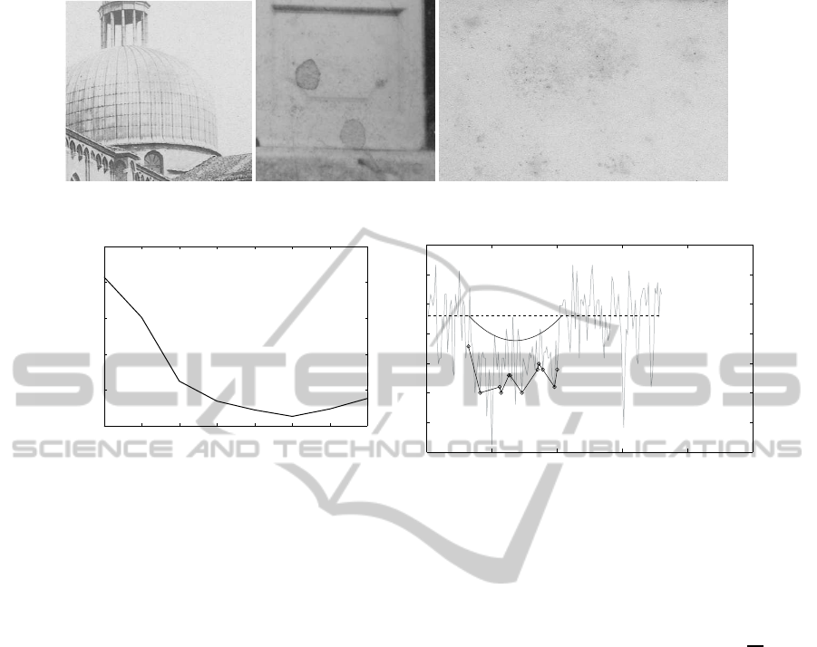
Figure 1: Examples of semi-transparent blotches in real photographs.
1 2 3 4 5 6 7 8
0
0.02
0.04
0.06
0.08
0.1
GROUPS
CONTRAST
0 50 100 150 200 250
0.76
0.78
0.8
0.82
0.84
0.86
0.88
0.9
z=(m+M+2∆)/2
Figure 2: Left: Contrast curve γ of B. Right: Plane section of a blotch (light gray), the surface of the i− th group (piecewise
curve) and the corresponding paraboloid (dark and solid line).
iii) ∀ g ∈ G ∃ g
−1
∈ G : g∗ g
−1
= g
−1
∗ g = e
and a differentiable manifold of finite dimension, i.e.
a space locally diffeomorphic to R
n
, if n is the dimen-
sion of G. Moreover the group operation ∗ and the
inverse map (G → G, g 7→ g
−1
) are C
∞
with respect
to the differentiable structure of the manifold. So a
Lie group G has algebraic properties coming from
the group structure and geometric properties coming
from the differentiable structure and they are related.
Finally, every finite Lie group can always be viewed
as a matrix group.
A Lie algebra g is a vector space endowed with a bi-
linear operation,
[ , ] : g × g → g, (X,Y) 7→ [X,Y],
called Lie bracket, antisymmetric and satisfying Ja-
cobi identity.
If G is a Lie group, its tangent space at identity,
g, which is a vector space, has a Lie algebra struc-
ture. Hence, g is a vector space of the same size of G
endowed with a Lie bracket. If G is a matrix group,
the Lie bracket is the matrix commutator, i.e. [X,Y] =
XY −YX. Since G is a differentiable manifold, there
exists a correspondence between its tangent space at
identity (the Lie algebra g) and G itself, that is the ex-
ponential map, exp : g → G. Let X ∈ g be a tangent
vector at e in G; locally there exists the integral curve
of X, a smooth curve starting from the identity with
tangent vector X, i.e. γ : [0, T] → G such that γ(0) = e
and
˙
γ(0) = X; we define exp(X) = γ(1). The exponen-
tial map is a local diffeomorphism around the origin
of g and it gives a natural way to move from g (vector
space) to G (manifold). For the matrix group, it corre-
sponds to matrix exponential: exp(X) =
∑
∞
n=0
X
n
n!
. For
a complete treatment of Lie groups and Lie algebras
see (Varadarajan, 1974) and (Helgason, 1962).
3.1 Lie Group Transformations
Most of the matrix Lie groups can be used to describe
transformations in the plane or in the space. For in-
stance, rotations in the plane are represented by the
group
SO
2
R =
cosθ sinθ
−sinθ cosθ
,θ ∈ R
.
The dimension of the group can be thought as
the number of free parameters needed to describe the
transformations. In case of plane rotation we just
need one parameter, θ, so the dimension of SO
2
R is
1. We can think about its Lie algebra elements, which
are tangent vectors at the identity, as the infinitesimal
transformations (rotation of an ’infinitesimal angle’)
of the points.
In this paper we are interested in using projec-
tive transformations in the space and they can be
described as a group matrix, P
3
, acting on the space
VISAPP 2012 - International Conference on Computer Vision Theory and Applications
68

points expressed in homogeneous coordinates, with
the convention that the fourth value in the coordinates
is always scaled back to 1. Projective transformations
are characterized by 15 parameters, that is the dimen-
sion of P
3
, described by the following basis of its Lie
algebra representing translations, scaling, shear and
projections:
G
1
=
0 0 0 1
0 0 0 0
0 0 0 0
0 0 0 0
,G
2
=
0 0 0 0
0 0 0 1
0 0 0 0
0 0 0 0
,G
3
=
0 0 0 0
0 0 0 0
0 0 0 1
0 0 0 0
,
G
4
=
0 0 0 0
0 0 1 0
0 −1 0 0
0 0 0 0
,G
5
=
0 0 −1 0
0 0 0 0
1 0 0 0
0 0 0 0
,
G
6
=
0 1 0 0
−1 0 0 0
0 0 0 0
0 0 0 0
,G
7
=
1 0 0 0
0 0 0 0
0 0 0 0
0 0 0 0
,
G
8
=
0 0 0 0
0 1 0 0
0 0 0 0
0 0 0 0
,G
9
=
0 0 0 0
0 0 0 0
0 0 1 0
0 0 0 0
,G
10
=
0 1 0 0
0 0 0 0
0 0 0 0
0 0 0 0
,
G
11
=
0 0 1 0
0 0 0 0
0 0 0 0
0 0 0 0
,G
12
=
0 0 0 0
0 0 1 0
0 0 0 0
0 0 0 0
,
G
13
= G
T
1
,G
14
= G
T
2
,G
15
= G
T
3
,
with T the transpose operator.
Hence, every real linear combination of
G
1
,...,G
15
is an infinitesimal projective transforma-
tion in the space that corresponds to a transformation
of the group P
3
thanks to the exponential map.
The infinitesimal transformation of a generic point
p =
h
x
y
z
i
is
˜
L
j
= G
j
x
y
z
1
j = 1, ..., 15 whose affine
coordinates L
j
respectively are
L
1
=
h
1
0
0
i
L
2
=
h
0
1
0
i
L
3
=
h
0
0
1
i
L
4
=
h
0
z
−y
i
L
5
=
h
−z
0
x
i
L
6
=
h
y
−x
0
i
L
7
=
h
x
0
0
i
L
8
=
h
0
y
0
i
L
9
=
h
0
0
z
i
L
10
=
h
y
0
0
i
L
11
=
h
z
0
0
i
L
12
=
h
0
z
0
i
L
13
=
h
x
2
xy
xz
i
L
14
=
xy
y
2
yz
L
15
=
h
xz
yz
z
2
i
.
3.2 Surfaces Distance Minimization by
Projective Transformation
The relation between Lie algebras and Lie groups al-
lows us to define an iterative procedure able to map a
given surface S
1
to another one, S
2
, in R
3
. ∀p ∈ S
1
, let
n
p
be the unit normal at S
1
in the point p and d
p
the
distance between p and S
2
along n
p
. Hence,
∑
p∈S
1
d
p
is the distance between S
1
and S
2
.
Let L
p
j
, for j = 1,..., 15, be the infinitesimal pro-
jective transformation L
j
applied to the point p. The
goal is to estimate 15 real parameters, α
1
,...,α
15
,
such that the infinitesimal projective transformation
∑
15
j=1
α
j
L
p
j
, projected onto the normal direction n
p
,
minimizes the distance between S
1
and S
2
, i.e.
(α
1
,... , α
15
) = min
α
j
∑
p∈S
1
"
d
p
−
15
∑
j=1
α
j
L
p
j
· n
p
#
2
.
Therefore,
~
α = (α
1
... α
15
)
T
is such that
~
α =
~
A
−1
~
b,
where the matrix
~
A and the column vector
~
b are
A
jk
=
∑
p∈S
1
L
p
j
· n
p
L
p
k
· n
p
and
b
k
=
∑
p∈S
1
d
p
L
p
k
· n
p
.
The exponential map transforms the infinitesimal
transformation G =
∑
15
j=1
α
j
G
j
into a projective trans-
formation T of the group i.e.,
T = exp(G) =
∞
∑
n=0
G
n
n!
.
Finally, S
1
is updated applying T to its points: S
(1)
1
=
T(S
1
). The minimization process can be then iterated
using the couples of curves (S
(1)
1
,S
2
), and so on.
For the numerical computation of exp(G) applied
to generic point x, a 4th order Runge Kutta algorithm
can be used — see (Drummond and Cipolla, 2000)
for details. It is equivalent to cut the 4th order series
expansion of the matrix exponential and apply it to
the point x, that is
T (x) ≈
I + G+
1
2
G
2
+
1
6
G
3
+
1
24
G
4
(x),
but it directly manages affine coordinates.
4 THE PROPOSED MODEL
Lie group transformations offer a redundant set of
transformations as well as a direct and fast method for
IMAGE RESTORATION VIA HUMAN PERCEPTION AND LIE GROUPS
69
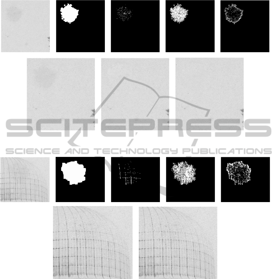
Figure 3: Top: Degraded image, its detection mask, D
1
, D
2
and D
3
masks. Bottom: Restored images after: processing D
1
(left), processing D
2
(middle) and final masking (right).
Figure 4: Top: Original degraded image, its detection mask, D
1
, D
2
and D
3
masks. Bottom: Restored images after: processing
D
2
(left) and final masking (right).
selecting them once the final target curve is known.
Unfortunately, in case of digital restoration the final
clean image is unknown. That is why some basic rules
of HVS are used for defining suitable ranges of inten-
sity values for the damaged area to be not visible with
respect to its neighborhood. Despite the wide flexibil-
ity of Lie transformations, the minimization process
is global. In other words, at each step the parameters
{α
j
}
j=1,...,15
are the same for each point. Hence, if on
one hand global transformations preserve the original
information contained in the degraded region, on the
other they forget that pixels may have been subjected
to a different amount of degradation.
In order to find a tradeoff between preservation of
original information and model flexibility,it is neces-
sary to classify damaged pixels accounting for their
visual importance and restore them accordingly.
4.1 Preprocessing of the Damaged Area
Let I be the analyzed image, B its damaged area and
let E be a sufficiently small neighborhood of B such
VISAPP 2012 - International Conference on Computer Vision Theory and Applications
70
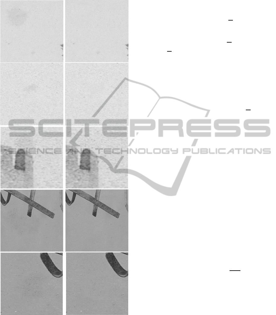
Figure 5: Original (left) and restored (right) images.
that we can assume that E and B share the same in-
formation. In order to classify the points in B accord-
ing to their contrast properties, the SMQT algorithm
(Nilsson et al., 2005) is used. It groups pixels having
comparable visual contrasts. More precisely, SMQT
builds a binary tree using the following rule: given a
set of data D and a real parameter L (number of lev-
els), split D into two subsets,
D
0
=
x ∈ D|D(x) ≤
D
and
D
1
=
x ∈ D|D(x) >
D
,
where D is the mean value of D. D
0
and D
1
are
the first level of the SMQT. The same procedure is re-
cursively applied to D
0
and D
1
and so on until the L
th
level, that is composed of 2
L
subsets. We set L = 3
in order to obtain a log
2
quantization of the dam-
aged pixels (i.e. 2
3
= log
2
(256) groups, B
1
,... , B
8
,
where [0,255] is the gray scale range) and will assume
B
1
,··· , B
8
ordered from the darkest to the brightest
pixel. We compute the inner contrast C
j
=
σ
j
µ
j
of each
B
j
, with σ
j
the standard deviation and µ
j
the mean of
B
j
. Let γ = {C
1
,··· ,C
8
} be the discrete contrast curve
of B, as in Fig. 2 (Left). Darker pixels in B, say D
1
,
are those sets B
j
whose inner contrast is greater than k
(where k is the least detection threshold given by the
Weber’s law, see (Winkler, 2005)). On the contrary,
brighter pixels in B, say D
3
, are those B
j
whose inner
contrast curve has positive first derivative. Let D
2
be
the union of the remaining groups.
Summing up, SMQT quantization of the degraded
region B combined with its contrast properties allows
to split B into three regions: the darkest, D
1
, the
brightest, D
3
and the central one, D
2
, where most of
information lives. The whole range of values of dam-
aged pixels has been then split into these three inter-
vals: [b
0
,b
1
], ]b
1
,b
2
[ and [b
2
,b
3
]. Let M and m be re-
spectively the maximum and the minimum value for
E (except for outliers). [m, M] is the range of admis-
sible values for the final solution. In fact, a natural
scene component is required to not exceed the range
of values of the surrounding information in terms of
visibility bounds. [m, M] is proportional to the global
contrast of the whole image I, i.e.
M− m
µ
I
where µ
I
is
the mean value of I. Since we are dealing with a lo-
cal degradation, we can think that any transformation
of the degraded region does not influence too much
µ
I
, so that it can be considered constant. That is why
from now on we will just deal with ranges instead of
contrasts.
The second goal of preproccesing is to understand
if each group of pixels must be moved. In fact, even
though the damaged area B appears darker than the
neighborhood E, it is important to check if the inter-
section between E and B values contains points that
are darker than the blotch, as it is the case for the
blotch on the dome in Fig. 1 (leftmost). To this aim, it
is necessary to check if the darker region of E, corre-
sponding to those pixels whose value is in the interval
IMAGE RESTORATION VIA HUMAN PERCEPTION AND LIE GROUPS
71

[b
0
,b
1
], masks D
1
. Setting the just noticeable thresh-
old ε = .33 (Pappas et al., 2005), if their contrast ra-
tio is included in [1− ε,1 + ε], then the same infor-
mation lives outside the blotch, and D
1
must be left
unchanged; otherwise D
1
must be transformed and
mapped into the range [m,M − δ], where δ is such
that [M − δ,M] and is proportional to [b
2
,b
3
]. It is
worth stressing that we choose to move D
1
values in
[m,M− δ] and not in [m,M] in order to preserve even-
tual original information.
With respect to D
3
, i.e. the brightest region of
B, we check if it is masked by the region in E cor-
responding to the values in the interval [b
2
,b
3
]. D
3
mostly corresponds to the transition area from E to B,
according to the physical properties of the damaged
area. Hence, the ratio between the inner contrasts is
included in [1− ε,1+ ε] and with high probability we
don’t need to transform it.
Finally, D
2
contains most of degradation and it must
be mapped into the interval [m, M]. However, because
of some rigidity of the model, it will be better to shift
the interval, i.e. [m+ ∆, M + ∆]. ∆ measures the dark-
ness of the damaged area and it is well represented by
the difference between the mean values of B and E.
4.2 Processing of the Damaged Area
The surfaces distance minimization described in sec-
tion 3.2 requires the definition of suitable surfaces
living in the transformation domains, [m+ ∆, M + ∆]
and [m,M − δ], of D
2
and D
1
. To preserve the origi-
nal information, HVS perception mechanisms can be
embedded in the restoration process. In particular,
we aim at processing in the same way points that
are equally perceived by human eye: points having
the same context (same visual contrast), have to con-
verge to the same target surface. To this aim, we ap-
ply the SMQT algorithm to D
2
. Each group in D
2
corresponds to a surface (defined by interpolation).
The target surface of the i-th group is defined as a
paraboloid cut by the plane
z =
m+ M + 2∆
2
and whose vertex is proportional to the mean value
of the group, according to the values interval. Each
surface converges to the corresponding paraboloid, as
shown in Fig. 2 (Right).
The iterative minimization process stops when the
target surface has been reached in agreement with vis-
ibility bounds. More precisely, let S be the initial sur-
face, S
n
the solution at the n-th iteration and P the
target paraboloid; S
n
is the final solution if
∑
x∈S
|S
n
(x) − P(x)|
∑
x∈S
P(x)
≤ k , (1)
where k is the least detection threshold given by We-
ber’s law. The first member of previous equation cor-
responds to Weber’s contrast evaluated at the points
of the analysed surfaces. For D
1
we use the same rule
with
z =
m+ M − δ
2
.
4.3 Masking Refinement
The iteration algorithm tends to preserve the original
information at the expense of some rigidity (solutions
tend to be dark). As a result, we need to stress the
range values relative to D
2
in order to have sufficiently
bright solutions and a sufficiently large range values
to avoid oversmoothed solutions. This requires a final
masking operation.
Specifically, let S
2
be the output of the minimiza-
tion algorithm applied to D
2
. LetV be the set of pixels
in S
2
whose value is greater than M− ε, that is
V = {p ∈ S
2
| v(p) > M − ε},
where v(p) is the value of the pixel p in S
2
and V
C
its
complementary set in S
2
. The ratio betweenV andV
C
is the inner contrast of S
2
. If this ratio is included in
[1 − ε, 1 + ε], we don’t need masking; otherwise, we
have to replace the values of some pixels in V with
their original ones.
The main idea is to replace those pixels that orig-
inally were sufficiently bright and that became too
bright in the minimization algorithm. More precisely,
let
H = {p ∈ V | v
orig
(p) > τ}
and
V
orig
= {v
orig
(p) | p ∈ V}
where v
orig
(p) is the original value of the pixel
p in D
2
and τ is a suitable constant related to the
properties of V
orig
, then S
2
(H) = V
orig
(H). Note that
τ =
¯
V
orig
+ ε, where
¯
V
orig
is the mean value of V
orig
.
4.4 Algorithm
Let I, B and E respectively be the initial image, the
degraded area and its neighborhood.
Step 1. Split B into the groups D
1
, D
3
and D
2
using
SMQT;
Step 2. Estimate the range of the solution [m, M]
from the surrounding information;
VISAPP 2012 - International Conference on Computer Vision Theory and Applications
72
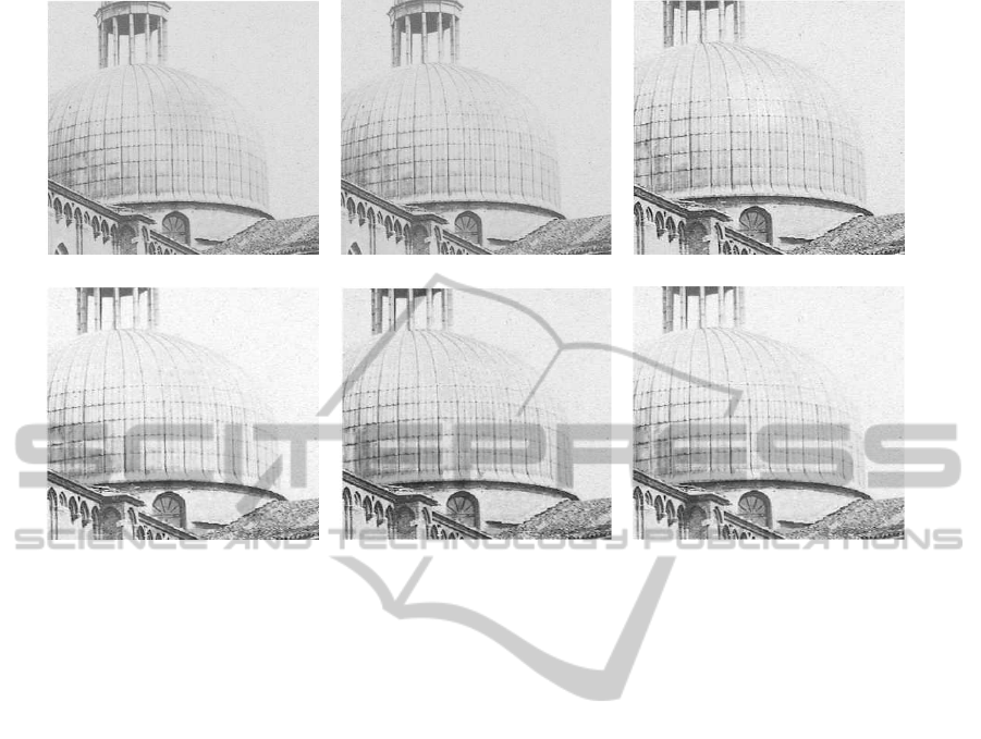
Figure 6: Blotch on a textured image. Top to bottom - left to right: degraded, restored image with the present method and
restored using methods in (Greenblatt et al., 2008), (Stanco et al., 2005), (Crawford et al., 2007) and (Bruni et al., 2011).
Step 3. Check if D
1
has to be processed; if so, go to
step 4, otherwise go to step 7;
Step 4. Apply SMQT to D
1
;
Step 5. Compute paraboloids including the solution
whose vertices are set according to the mean am-
plitudes of the groups computed in step 4 and the
output of step 2;
Step 6. For each group in step 4, apply the iterative
procedure in Section 3.2 where the target surfaces
are the ones computed in step 5, until eq. (1) is
satisfied;
Step 7. Apply steps 4-5-6 to D
2
;
Step 8. Perform masking refinement.
Fig. 3 shows the results of some steps of the algo-
rithm. In this case D
1
must be processed: the initial
contrast ratio between D
1
and its corresponding exter-
nal area is 2.5. On the contrary, the one between D
3
and its corresponding external region is 0.8; hence it
is not necessary to process it.
For the blotch in Fig. 4, both D
1
and D
3
don’t
need to be processed — contrast ratios respectively
are 1.1 and 0.9.
5 EXPERIMENTAL RESULTS
AND CONCLUDING REMARKS
The proposed approach has been tested on selected
images from the photographic Alinari Archive in Flo-
rence, affected by semi-transparent defects. Some re-
sults are shown in Figs. 5 and 6. As it can be ob-
served, the visual appearance of the recovered images
is very good: no artifacts appear, the texture of the
background is well recovered as well as eventual de-
tails of the original image (see, for example, the edges
of the dome).
The use of a selective algorithm avoids annoying
halo effects at the border of the defect along with
over-smoothing in the inner part of the restored re-
gion. As a result, the restored region is not still per-
ceived as an anomaly on the image. The convergence
process is different for each group of points so that
it could happen that some groups converge after one
or two iterations while others require longer conver-
gence time. In that way the over-smoothing is avoided
and the preservation of the inner information is guar-
anteed via the visibility based stopping criterion in eq.
(1).
Moreover, the preprocessing of the damaged area
and masking procedures allow the detection mask to
be not precise (it can be larger than the degraded re-
IMAGE RESTORATION VIA HUMAN PERCEPTION AND LIE GROUPS
73

gion) and to manage complicated cases where the de-
graded area intersects a darker region of the image
as in Fig. 5, so that restoration does not create arti-
facts in correspondence to not degraded pixels. This
is a great advantage, since the detection mask heavily
influences restoration results of available restoration
frameworks.
It is also worth highlighting that even though the
proposed algorithm involves iterative procedures, it
uses simple and fast operations and 4/5 iterations on
average to converge.
Future research will be oriented to refine the pro-
posed model to make it more flexible and adaptive to
different amount of degradation while faithfully pre-
serving original image information.
REFERENCES
Bertalmio, M., Sapiro, G., Caselles, V., and Bellester, B.
(2000). Image inpainting. In Proceedings of SIG-
GRAPH 2000.
Bertalmio, M., Vese, L., Sapiro, G., and Osher, S. (2003).
Simultaneous structure and texture image inpainting.
In IEEE Transactions on Image Processing, 12(8).
Bruni, V., Crawford, A., Kokaram, A., and Vitulano, D.
(2011). Semi-transparent blotches removal from sepia
images exploiting visibility laws. In Signal Image and
Video Processing. Springer-Verlag.
Crawford, A., Bruni, V., Kokaram, A., and Vitulano, D.
(2007). Multiscale semitransparent blotch removal
on archived photographs using bayesian matting tech-
niques and visibility laws. In Proceedings of In-
ternational Conference on Image Processing (ICIP
2007),S. Antonio, Florida. IEEE Signal Processing
Society.
Criminisi, A., Perez, P., and Toyama, K. (2004). Region
filling and object removal by exemplar-based image
inpainting. In IEEE Transactions on Image Process-
ing, 13(9). IEEE Signal Processing Society.
Drummond, T. and Cipolla, R. (2000). Application of lie
algebras to visual servoing. In International Journal
of Computer Vision, 37(1).
Efros, A. and Freeman, W. (2001). Image quilting for tex-
ture synthesis and transfer. In Proceedings of SIG-
GRAPH 2001.
Greenblatt, A., Agaian, S., and Panetta, K. (2008). Restora-
tion of images damaged by semi-transparent water
blotches using localized image enhancement. In Pro-
ceedings of SPIE 2008.
Helgason, S. (1962). Differential geometry and symmet-
ric spaces. Pure and Applied Mathematics, Vol. XII.,
Academic Press, New York-London.
Kokaram, A. (1998). Motion Picture Restoration. Digital
Algorithms for Artefact Suppression in Degraded Mo-
tion Picture Film and Video. Springer Verlag.
Kokaram, A. (2002). Parametric texture synthesis for fill-
ing holes in pictures. In Proceedings of International
Conference on Image Processing (ICIP 2002). IEEE
Signal Processing Society.
Mansouri, A. and Mukherjee, D. (2004). Constraining ac-
tive contour evolution via lie groups of transforma-
tion. In IEEE Transactions on Image Processing,
13(6). IEEE Signal Processing Society.
Mukherjee, D. and Acton, S. (2007). Affine and projective
active contour models. In Pattern Recognition, 40(3).
Elsevier Science Inc.
Nilsson, M., Dahl, M., and Claesson, I. (2005). The succes-
sive mean quantization transform. In Proceedings of
ICASSP. IEEE Signal Processing Society.
Pappas, T., Safranek, R., and Chen, J. (2005). Perceptual
criteria for image quality evaluation. In Handbook of
Image and Video Processing. Academic Press.
Porikli, F., Tuzel, O., and Meer, P. (2006). Covariance track-
ing using model update based on lie algebra. In Pro-
ceedings of the IEEE Conference on Computer Vision
and Pattern Recognition (CVPR 2006).
Stanco, F., Tenze, L., and Ramponi, G. (2005). Virtual
restoration of vintage photographic prints affected by
foxing and water blotches. In Journal of Electronic
Imaging, 14(4).
Varadarajan, V. (1974). Lie groups, Lie algebras and their
representations. Prentice-Hall Series in Modern Anal-
ysis. Prentice-Hall.
Winkler, S. (2005). Digital Video Quality. Vision Models
and Metrics. Wiley.
VISAPP 2012 - International Conference on Computer Vision Theory and Applications
74
