
HEIGHT ESTIMATION FROM A SINGLE CAMERA VIEW
Mahdi Momeni-K.
1
, Sotirios Ch. Diamantas
2
, Fabio Ruggiero
3
and Bruno Siciliano
3
1
Ecole Centrale de Nantes, 44321 Nantes cedex 3, France
2
Intelligent Robot Lab, School of Electrical Engineering, Pusan National University, 609-735 Busan, Republic of Korea
3
PRISMA Lab, Dipartimento di Informatica e Sistemistica, Universit`a degli Studi di Napoli Federico II, Napoli, Italy
K
eywords:
Height Estimation, Monocular Camera, Vanishing Point.
Abstract:
This paper presents a novel technique for the estimation of the height of an object using a single camera view.
In the proposed method, the only information required is the knowledge about the pose of the camera with
respect to the world (i.e., height and pitch angle of the camera with respect to the ground) and a vanishing
point. In the developed theory, the focal length may also be known, but in the proposed experiments it has
not been employed: an approximation for small pitch angles has been taken into account and the consequent
committed error has been then analysed. The presented method gives accurate results for any object placed in
unstructured environments, regardless of the relative distance from the camera. The method has been tested in
a series of outdoor and indoor environments, and the experimental results are presented in this paper.
1 INTRODUCTION
Visual information constitutes a core part in image
processing field and in robotics science. The appli-
cation areas are numerous and range from single view
metrology, object recognition, autonomous robot nav-
igation, visual servoing and so on.
In this paper, the problem of height estimation is
addressed. In particular, the height of an object, ir-
respective of its distance from the camera, is com-
puted by using only the knowledge about the pose of
the camera (i.e., height and pitch angle of the camera
with respect to the ground) and a vanishing point, no
matter if this last is in the image plane or not. Focal
length should also be known in theory, but in practi-
cal application it is employed when large pitch angles
arise. Moreover, the object can be placed in any kind
of environment since the proposed method can eas-
ily employ some rough object detection techniques
in order to recognize the object in the scene – pro-
vided that the object is distinguishable from the back-
ground. Hence, in the proposed methodology, it is
not required to estimate the vertical vanishing lines,
the reference direction vanishing point, and the 3D
properties from the 2D images are not detected.
The employed assumptions are very often fulfilled
in the aforementioned applications. For instance, in
robotics, a UAV usually employs an attached camera
in order to retrieve some information about the exter-
nal environment (Nonami et al., 2010). Hence, for in-
stance, the proposed method could be useful in order
to detect the objects’ height during the vehicle’s path
so as to avoid them during the flight. The position of
the camera can be recovered by knowing the vehicle
attitude and altitude with respect to the ground. Other
important applications can be considered the image
processing field, robot navigation (Angelova et al.,
2006), single view metrology.
This paper comprises five sections. Following is
Section 2 where the related works in height estima-
tion and their application areas are presented. In Sec-
tion 3 the methodology of estimating object height is
described. Section 4 presents the results of the ap-
proach and gives a comparison with existing methods.
Finally, Section 5 epitomizes the paper with a discus-
sion on the conclusions drawn from this research as
well as the future prospects of this method.
2 RELATED WORKS
A significant number of works tackles the prob-
lem of height estimation using calibrated cameras.
(Viswanath et al., 2009) describe a simple model of
error distribution in the computed height as a func-
tion of the location of the object and the recovered
height of the camera. In their approach they estimate
the vanishing points and the horizon line in order to
358
Momeni-K. M., Ch. Diamantas S., Ruggiero F. and Siciliano B..
HEIGHT ESTIMATION FROM A SINGLE CAMERA VIEW.
DOI: 10.5220/0003866203580364
In Proceedings of the International Conference on Computer Vision Theory and Applications (VISAPP-2012), pages 358-364
ISBN: 978-989-8565-03-7
Copyright
c
2012 SCITEPRESS (Science and Technology Publications, Lda.)

compute the height of the camera. Upon completion
of this task, they calculate the height of the object
of interest and then they select an error model in or-
der to correct the estimated height. Their approach is
demonstrated on an object tracking scenario. (Crim-
inisi et al., 2000) describe various methods for esti-
mating the height of an object using an uncalibrated
camera. In their work, they describe how the affine
3D geometry of a scene can be measured by a single
perspective image. Their approach is based on the es-
timation of the vanishing line of the ground plane and
the vertical vanishing point. Nevertheless, errors ap-
pear in the estimated height of the object since these
accrue from errors in estimating the ground plane and
in estimating the 3D position of the object. In a more
recent attempt, (Pears et al., 2005) propose a method
for height estimation using the height of an object as
a reference in order to correctly scale affine height
measurements to Euclidean ones. In their approach,
the authors segment the ground plane from the visual
field of view of a mobile robot and estimate the height
of objects that lie above the ground plane of the robot.
In addition to the previous work, (Chen et al., 2006)
present a visual metrology method by using uncali-
brated images separated by a near pure translation.
This approach has been applied to two cases, one for
detecting obstacles in a mobile robot application and
a second one for measuring the height of doorways,
windows, and other furniture. In the first case the
authors use the camera height as a known parameter
whereas in the second case they use a reference object
with a known height. (Cai and Walker, 2010) estimate
the height of trees and power lines from an unmanned
aerial vehicle. In this research sequential images are
captured by a single camera and with known distances
of at least two objects are able to infer the height of the
objects. The use of dynamic programming for stereo
matching provides depth information in occluded re-
gions.
Human height estimation has been a thriving field
of interest the last few years with applications in
forensic image analysis, video surveillance, and hu-
man tracking. (BenAbdelkader and Yacoob, 2008)
present a method where they are able to estimate
the height of human body without using a reference
length in the image plane. In addition, their estima-
tion can be achieved when the upper body of a hu-
man is visible. For their method they use a statisti-
cal method in the Bayesian-like framework. The in-
trinsic and extrinsic parameters of the camera need
not to be known, and thus the camera may even be
uncalibrated. In a similar case, (Jeges et al., 2008)
estimate the human height using a calibrated cam-
era. In this research the authors estimate the height
of humans along with the process of calibrating the
camera. Their application area has been in tracking
humans in intelligent surveillance systems. (Guan,
2009) presents a method for estimating the human
stature based on the human face. In this approach a
single image and a calibrated camera are used for es-
timating the stature. The author takes into consider-
ation the ratios of features in the human face to esti-
mate the stature of a human: in particular, the vertical
proportions of the human face remain unchanged dur-
ing human growth. Thus, based on the golden section
rule that governs the human face, an estimation of the
human stature is achieved.
In robot navigation the extraction of vertical lines
has been used by (Zhou and Li, 2007) where the au-
thors exploit the vertical lines of an indoor environ-
ment in order to make the robot able to navigate au-
tonomously. Furthermore, based on the camera ori-
entation which is inferred by the extraction of vertical
lines, their system detects and hence avoids obstacles.
Finally, (Sun et al., 2006) make use of stereo vision in
order to infer the height of vegetation from the power-
lines. The proposed method makes use of images cap-
tured by an airborne system and a stereo vision sys-
tem that recovers the surface of vegetation. The sys-
tem identifies power poles and measures the distance
between the vegetation and the modelled line.
3 METHODOLOGY
This section presents the method followed for the es-
timation of the height of an object. First, the notation
and the basic assumptions are presented,then the key
theorems are introduced, while in the remainder the
core of the methodology is described.
3.1 Basic Assumptions
The premise to find vanishing points is to consider
environments which contain parallel straight lines.
When looking at the perspective projection of 3D
parallel lines, they intersect in one common point
in the image plane, which is the so called vanish-
ing point (Hartley and Zisserman, 2004). Vanish-
ing points, therefore, represent the projections of 3D
points laying at infinity, since parallel lines intersect
at infinity (Saurer et al., 2010). However, depending
on the orientation of the camera, the vanishing point
may be either inside or outside of the camera field of
view. Furter, a camera can be characterized by the
so called intrinsic and extrinsic parameters (Siciliano
et al., 2008): the former depend on the lens and sensor
characteristics; the latter on the relative pose between
HEIGHT ESTIMATION FROM A SINGLE CAMERA VIEW
359

a frame attached to the camera and a fixed reference
frame, usually attached to the ground.
The goal of this work is to find the height of an
object in the observed scene on the basis of the fol-
lowing assumptions:
• It is possible to measure both the height of the
camera and the angle of the optical axis (i.e. pitch
angle) with respect to the ground.
• It is possible to extract a vanishing point.
• In the developed theoretical framework, the cam-
era focal length should be known. This infor-
mation can be retrieved from the camera data-
sheet, since this is not the usual (2× 1) vector that
comes out from the common calibration proce-
dures. However, in the experiments, this assump-
tion will be relaxed.
• If automatic techniques about object recognition
would be used in the experiments, then the object
has to be distinguishable from the background.
In order to compute the height of an object in me-
ters, its height in pixel has to be known. Then, the
key of the methodology is to obtain the ratio between
pixel and meters in the observed scene: by knowing
the camera height in the real 3D world, it would be
possible to compute such a ratio if it is allowed to rec-
ognize the camera height in pixels in the image plane.
Since the further away the object from the camera is,
the smaller the size it has on the image plane, then the
pixel-height of the camera should be computed at the
same position of the object in the image plane.
3.2 Basic Theorems
With reference to Fig. 1, consider a world fixed frame
Σ
w
= O
w
− x
w
y
w
z
w
and a frame Σ
c
= O
c
− x
c
y
c
z
c
at-
tached to the camera, whose origin O
c
is at the lens
center; further, consider a reference frame on the im-
age plane, whose axesU andV are parallel to the axes
x
c
and y
c
of Σ
c
, and whose origin is at the intersection
of the optical axis with the image plane, termed prin-
cipal point. Let β be the pitch angle with respect to
the ground, that is the angle between the axes z
c
and
z
w
around x
w
, and where positive rotations are con-
sidered counter-clockwise. Finally, consider a fixed
virtual frame Σ
v
= O
v
− x
v
y
v
z
v
that is coincident to
the camera frame when the pitch angle β is zero. It
comes out that the pitch angle can also be seen as the
angle between the axes z
c
and z
v
around x
v
.
By considering the frontal perspective projec-
tion model – radial distortion can be neglected since
this does not affects the method (Guan, 2009) –
, a point p
c
=
p
c
x
p
c
y
p
c
z
T
, whose coordinates
are expressed with respect to Σ
c
, will project from
IMAGE PLANE
LENS
CENTER
U
V
y
v
z
v
z
c
y
c
ᵝ
f
x
w
y
w
z
w
O
c
Figure 1: Significant frames employed in the proposed
methodology. In order to simplify the figure, the axes x
c
and x
v
have not been drawn, while the image plane has been
depicted in the condition β = 0.
the 3D scene onto the image plane with coordinates
u v
T
in the UV-frame through the following ex-
pression (Hutchinson et al., 1996):
u v
T
= ( f/p
c
z
)
p
c
x
p
c
y
T
(1)
where, f is the focal length of the camera. All ob-
jects in the field of view of the camera, therefore, will
project onto the 2D image plane through the nonlinear
equation in (1).
Suppose now to have two points with equal com-
ponent on the axes x
c
and z
c
in the camera frame, but
different components on the y
c
axis: the following
theorem can be thus introduced.
Theorem 1. Although two points are projected from
the 3D scene onto the 2D image plane through the
nonlinear equation (1), the ratio between the two dif-
ferent y
c
components will remain unchanged, as long
as they have the same values for the other two com-
ponents, with all the quantities expressed with respect
to the camera frame.
Proof. Two points P
1
=
p
c
x
1
p
c
y
1
p
c
z
1
T
and P
2
=
p
c
x
2
p
c
y
2
p
c
z
2
T
are projected onto the image plane
through (1). Since the two points have the property
that p
z
1
= p
z
2
and p
x
1
= p
x
2
, it is possible to write
u
1
= ( f/p
z
1
)p
x
1
v
1
= ( f/p
z
1
)p
y
1
u
2
= ( f/p
z
1
)p
x
1
v
2
= ( f/p
z
1
)p
y
2
(2)
By comparing the two systems in (2), it yields to
v
1
/v
2
= p
y
1
/p
y
2
, (3)
with u
1
= u
2
, and this proves the theorem.
The direct result of Theorem 1 is that the ratio of
the y
c
-coordinates in the camera frame of any two
VISAPP 2012 - International Conference on Computer Vision Theory and Applications
360
LENS
CENTER
y
v
z
v
z
c
y
c
ᵝ
f
O
c
P
1
P
2
v
2
ᵝ
v
1
ᵝ
IMAGE PLANE
IMAGE PLANE
v
1
v
v
2
v
f
Π
Π ᵝ
v
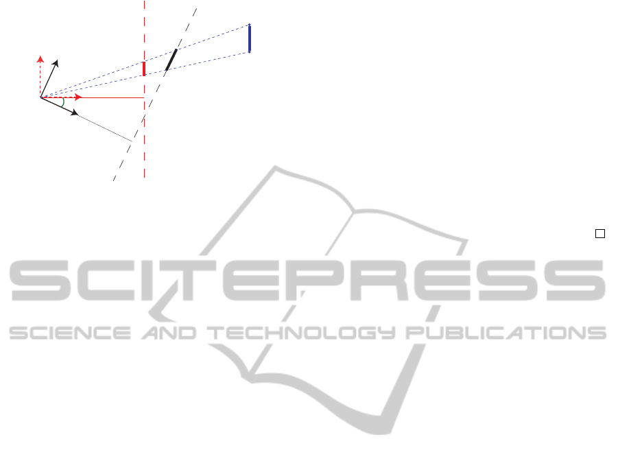
Figure 2: Frontal perspective projection of a segment in two
images planes with a different camera orientation. In red the
case of β = 0 (i.e., Σ
c
is coincident with Σ
v
), while in black
the case of a generic pitch angle β.
points laying along a line parallel to the axis y
c
in
the 3D world, remains equal to the ratio of the v-
coordinates once these same points are projected in
the 2D image plane.
Now, it is introduced a theorem that relates the
projections of a point from the 3D world onto two
different image planes.
Theorem 2. By knowing the v-coordinate v
β
of the
projection of a 3D point P onto an image plane Π
β
,
associated with a camera whose optical axis has an
angle β with respect to ground, it is possible to com-
pute the v-coordinate v
v
of the projection of the same
3D point onto the image plane Π
v
, associated with a
virtual camera whose frame is coincident with the Σ
v
.
In particular, the following relationship holds:
v
v
= f(v
β
cosβ− f sinβ)/(v
β
sinβ+ f cosβ). (4)
Proof. With reference to Fig. 2, consider a point P
in the 3D space, the virtual reference frame Σ
v
and a
camera frame Σ
c
whose optical axis has a pitch an-
gle β with respect to the ground. The v-coordinate of
the projection of the point P onto the image plane Π
β
associated to Σ
c
is denoted with v
β
. Without loss of
generality, consider that the u-coordinate of the pro-
jection of the point P is zero.
From the definition of the frontal perspective
model, the 3D coordinates of the projection of the
point P onto Π
β
with respect to the camera frame
Σ
c
is represented by the vector p
c
β
=
U V f
T
=
0 v
β
f
T
. Pre-multiplying such a vector for the
well-known expression of the rotation matrix R
v
c
(Si-
ciliano et al., 2008) that represents the rotation of
the frame Σ
c
with respect to the frame Σ
v
around
the axis x
v
, it is thus possible to express p
c
β
with
respect to the frame Σ
v
. Hence, p
v
β
= R
v
c
p
c
β
=
0 v
β
cosβ− f sinβ v
β
sinβ+ f cosβ
T
.
The optical ray that passes through the lens center,
the point P and both the projections of P onto Π
β
and
Π
v
is then represented by the following straight line
equations with respect to the frame Σ
v
x
v
= 0
y
v
=
v
β
cosβ− f sinβ
t
z
v
=
v
β
sinβ+ f cosβ
t
, (5)
where t parametrizes such straight line. The intercep-
tion of (5) with the image plane Π
v
, whose equation
is z
v
= f with respect to the frame Σ
v
, yields to
f =
v
β
sinβ+ f cosβ
t (6)
that gives the projection of the point P onto Π
v
. By
computing t from (6) and by substituting it into y
v
in
(5), it is hence possible to prove the theorem.
From the aboveTheorem 2 it is possible to retrieve
the following corollary.
Corollary 1. With reference to Fig. 2, by knowing the
v-coordinates v
β
1
and v
β
2
of the projections of two 3D
points P
1
and P
2
, respectively, onto the image plane
Π
β
, it is possible to compute the v-coordinates v
v
1
and
v
v
2
of the same two 3D points P
1
and P
2
, respectively,
onto the image plane Π
v
, that is as the camera had no
pitch angle with respect to the ground. In particular
such relation holds
| v
v
1
− v
v
2
|= f
2
| v
β
1
− v
β
2
| /γ
β
, (7)
where γ
β
=|
v
β
1
sinβ+ f cosβ
v
β
2
sinβ+ f cosβ
|,
and where | · | denotes the absolute value operation.
The direct result of the Theorem 2 and of the Corol-
lary 1 is that if it is possible to compute the length of
a segment in pixel in an image plane whose camera
frame has a certain pitch angle β, it is then possible
to have the pixel length of the same segment as the
camera had the optical axis parallel to the ground.
3.3 Methodology Steps
Another direct consequence of the Theorem 1 is that
the ratio of the height of any two adjacent objects in
image plane represents the ratio of the two adjacent
objects in the real 3D environment. As a result, by
knowing the proportion of camera height w.r.t. the ob-
ject height, at the object’s position in the image plane,
it would be possible to estimate the height of the ob-
ject in the real world. To this end, denoting with H
c
the height of the camera with respect to Σ
w
, H
c
p
the
height of the camera in pixel, H
o
the height of the ob-
ject with respect to Σ
w
and H
o
p
the height of the object
in pixel, the following relationship holds
H
c
/H
c
p
= H
o
/H
o
p
. (8)
HEIGHT ESTIMATION FROM A SINGLE CAMERA VIEW
361

The information about H
c
is given by the assump-
tions, while H
o
p
can be retrieved by the acquired pic-
ture, thus the problem is to compute the height of the
camera H
c
p
in the image plane.
Consider the frame Σ
v
, the associated image plane
Π
v
and a plane Π
g
parallel to the ground that contains
also the axis z
v
: this plane and the ground plane meet
each other at infinity and they form a line that contains
a vanishing point. Since the optical lens center, that is
the origin of Σ
v
, belongs to Π
g
, this plane and thus the
vanishing point can be used as a reference in order to
find out the height of the camera in the image plane
Π
v
. In particular, this implies the following Lemma.
Lemma 1. The distance between a point on the
ground plane and the v-coordinate of the vanishing
point in the image plane, and thus the horizontal line
that passes through the vanishing point, represents
the height of the camera in pixel.
Hence, the above Lemma 1 implies that, in the im-
age plane Π
v
, the v-distance between the ground at the
object position and the vanishing point represents the
height of the camera in pixel. By computing also the
height of the object in pixel, it would be possible to
apply equation (8), thanks to Theorem 1, in order to
get the height of the object in the 3D world. However,
the above Lemma 1 has been derived with respect to
Σ
v
, while in a general case the camera can havea pitch
angle with respect to the ground. Hence, it is only
possible to compute in pixel both the camera and the
object height into the image plane Π
β
. In order to
follow Lemma 1 and thus to apply equation (8), it is
necessary to employ equation (7) so as to refer to all
the quantities with respect to the virtual frame Σ
v
.
Then, to recap, the following steps are proposed
in order to get the height of an object:
1. Take a picture of the current scene with the object
in the camera field of view. Then, extract the van-
ishing point and the outlines of the object in the
image plane Π
β
.
2. The v-distance between the lower end-point and
the upper end-point of the object’s outline repre-
sents the height of the object in pixel.
3. The v-distance between the lower end-point’s cor-
responding point on the ground plane and the v-
coordinate of the vanishing point represents the
height of the camera in pixel at object’s position.
4. Use equation (7) in order to refer to the above
quantities with respect to Σ
v
, so as to project the
segments from Π
β
into Π
v
, in order thus to get
H
o
p
and H
c
p
, respectively.
5. Use equation (8) in order to estimate the height of
the object H
o
.
4 EXPERIMENTS
This section presents the results about the proposed
method, based on experimental work in both indoor
and outdoor environments.
4.1 Technical Details
The experimental set-up implementing the proposed
methodology for the indoor environment is composed
of an industrial USB iDS UEYE UI-1220SE-C cam-
era mounted directly on the end-effector of a Comau
Smart-Six robot manipulator, that it has been em-
ployed in order to carry around the camera in all the
acquisition stations. By using such a robotic set-up,
it is easier to retrieve the information about the pitch
angle β and the height of the camera H
c
. The acquired
images have a resolution of (752× 480) pixel.
For what concerns the outdoor experiment, in-
stead, the pocket camera SONY DSC-TX9 with 12.2
megapixels resolution has been employed, while a tri-
pod with spirit level has been used so as to verify that
the camera was parallel to the ground.
The outlines of the object have been extracted
manually, since the employed objects were not so
clearly distinguishable from the background. In par-
ticular, the segmentation algorithm used in (Hoiem
et al., 2007), has been tested in order to automatically
detect the objects’ contours, but the obtained results
were not so robust.
The vanishing point has also been extracted man-
ually from the captured images. However, with the
automatic methods explained by (Kongand et al.,
2009), (Rother, 2002), (Schmitt and Priese, 2009), it
has been verified that the obtained results were robust
enough even by using such algorithms.
It is worth noting that equation (7) can be simpli-
fied if small pitch angles are employed:
| v
v
1
− v
v
2
|≃| v
β
1
− v
β
2
|, when β ≃ 0, (9)
thus, in those cases, it is useless to consider the focal
length f. Hence, the followingexperiments have been
performed by considering small pitch angles, so as to
stress the proposed methodology. The error in pixel
that is carried out is as follows
e = f
2
| v
β
1
− v
β
2
| /γ
β
− | v
β
1
− v
β
2
|, (10)
obtained by subtracting the employed approximation
(9) from the theoretical value (7).
4.2 Results and Discussion
In Table 1 the results obtained during the experiments
have been summarized: the first column denotes the
VISAPP 2012 - International Conference on Computer Vision Theory and Applications
362
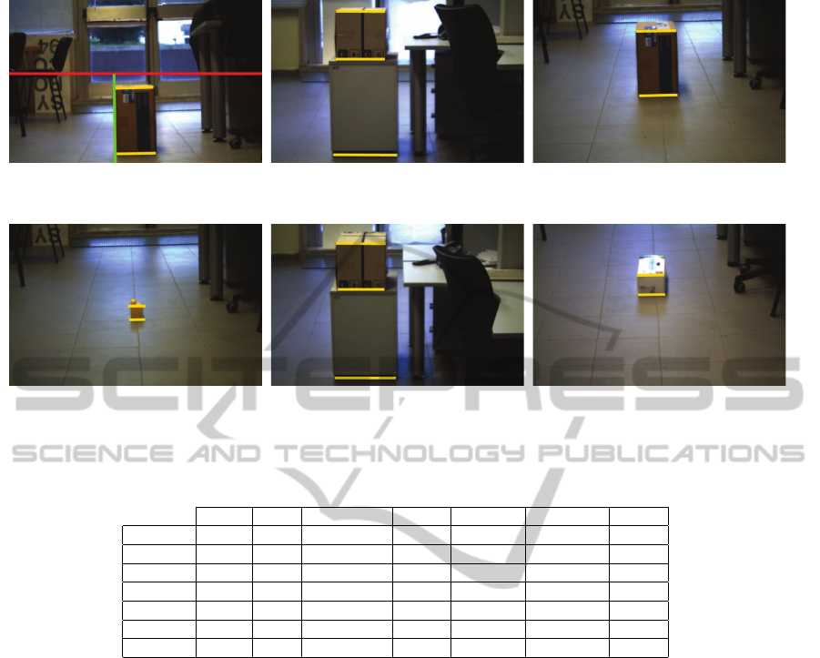
3.1: Actual height of the object is 36 cm, estimated
height is 36.3 cm, and β = 0
◦
.
3.2: Actual height is 29.6 cm, estimated height is
29.9 cm, and β = −7
◦
.
3.3: Actual height is 36 cm, estimated height is
35.7 cm, and β = −10
◦
.
3.4: Actual height is 8.1 cm, estimated height is
8 cm, and β = −10
◦
.
3.5: Actual height is 29.6 cm, estimated height is
29.1 cm, and β = −15
◦
.
3.6: Actual height is 12.3 cm, estimated height is
11.4 cm, and β = −20
◦
.
Figure 3: Collection of the pictures about the indoor experiments.
Table 1: Table of results.
Cam. Env. Cam.’s H. β Real H. Estim. H. Error
Fig. 3.1 USB I 45.15 cm 0
◦
36 cm 36.3 cm 0.8%
Fig. 3.2 USB I 107.25 cm −7
◦
29.6 cm 29.9 cm 1%
Fig. 3.3 USB I 79.87 cm −10
◦
36 cm 35.7 cm 0.8%
Fig. 3.4 USB I 79.87 cm −10
◦
8.1 cm 8 cm 1.2%
Fig. 3.5 USB I 168.90 cm −15
◦
29.6 cm 29.1 cm 1.7%
Fig. 3.6 USB I 134.42 cm −20
◦
12.3 cm 11.4 cm 7.3%
Fig. 4 TX9 O 115 cm 0
◦
176 cm 175.6 cm 0.2%
considered figure; in the Cam. column it is reported
the employed camera model for the current picture;
the symbols I or O under column Env. denote an in-
door or outdoor environment respectively, while the
height of the camera is mentioned in the Cam.’s H.
column; the pitch angle is reported in the column β;
the real height of the object and the estimated height
are given in the Real H. and Estim. H. columns, re-
spectively, and finally, in the Error column, the per-
centage of error with respect to the real height of the
considered object is underlined.
In Figs. 3.1 and 4 the vanishing point is inside the
image plane, while in Figs. 3.2-3.6 it is outside the
image plane. A small change of the illumination can
be noticed throughout all the figures, and this does not
affect the method, as long as the object contours ex-
traction methods are robust enough. In Figs. 3.2 and
3.5, the object is located on top of a cupboard so that
three objects can be considered: the box, the cupboard
and the “total” object given by the box over the cup-
board. In order to estimate the height of the box, first
the total height of the box over the cupboard, then the
height of the cupboard have to be estimated: thus, by
deducting the latter from the former, it is possible to
compute the height of the box. Since the heights of
two objects have to be computed to have in turn the
desired height, because of the small pitch angles as-
sumption, the total error on the final result is the sum
of the errors after the two previous estimations. Fur-
ther, it can be noticed the larger is β, the larger is the
error: this comes out by considering (9) in lieu of (7).
By considering the focal length f, it would be possi-
ble to reduce such errors.
On the basis of the previous experimental results,
it can be seen that the method is general and yields to
results which are achieved without the need of any
other reference inside and/or outside of the image
plane. The method by (Criminisi et al., 2000) yields
to accurate results too, but a reference height in the
image plane is used. As an example, in order to esti-
mate the height of a person who is standing beside the
phone box (refer to Fig. 10 in (Criminisi et al., 2000)),
not only they need to detect the vanishing line of the
ground plane, but also they need to detect the edges
HEIGHT ESTIMATION FROM A SINGLE CAMERA VIEW
363
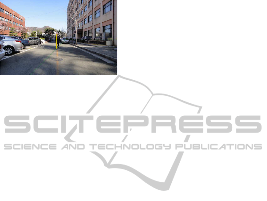
Figure 4: Actual height of the person is 176 cm, estimated
height is 175.6 cm, and β = 0
◦
.
of the phone box in order to compute the vertical van-
ishing point. Whereas, using the proposed method,
this goal can be achieved with only the previously de-
clared assumptions (see the experiment performed in
Fig. 4). On the other hand, (Guan, 2009) presents
a method for human height estimation based on the
human face. In his approach, the author exploits the
fact that the vertical proportions of the human face re-
main unchanged during human growth. He also used
a calibrated camera in order to achieve this task. Al-
though his method is accurate enough, it is dependent
on accurate camera calibration: besides this, a face
recognition program is needed.
5 CONCLUSIONS AND FUTURE
WORK
In this paper, an efficient and robust method for esti-
mating the object height using the camera pose with
respect to the world and a vanishing point has been
described. The accuracy of the proposed method has
been experimentally proven in outdoor and indoor en-
vironments. Future work will be focused on taking
into account also roll and yaw rotations of the cam-
era, and by considering a most automated process.
REFERENCES
Angelova, A., Matthies, L., Helmick, D., and Perona, P.
(2006). Slip prediction using visual information.
In Proceedings of Robotics: Science and Systems,
Philadelphia, USA.
BenAbdelkader, C. and Yacoob, Y. (2008). Statistical body
height estimation from a single image. In Proceed-
ings of the 8th IEEE International Conference on Au-
tomatic Face and Gesture Recognition, pages 1–7.
Cai, J. and Walker, R. (2010). Height estimation from
monocular image sequences using dynamic program-
ming with explicit occlusions. IET Computer Vision,
4(3):149–161.
Chen, Z., Pears, N., and Liang, B. (2006). A method of
visual metrology from uncalibrated images. Pattern
Recognition Letters, 27(13):1447–1456.
Criminisi, A., Reid, I., and Zisserman, A. (2000). Single
view metrology. International Journal of Computer
Vision, 40(2):123–148.
Guan, Y.-P. (2009). Unsupervised human height estimation
from a single image. Journal of Biomedical Science
and Engineering, 2(6):425–430.
Hartley, R. and Zisserman, A. (2004). Multiple View Geom-
etry in Computer Vision. Cambridge University Press,
second edition.
Hoiem, D., Efros, A., and Hebert, M. (2007). Recovering
surface layout from an image. International Journal
of Computer Vision, 75(1):151–172.
Hutchinson, S., Hager, G. D., and Corke, P. I. (1996). A
tutorial on visual servo control. IEEE Transactions on
Robotics and Automation, 12(5):651–670.
Jeges, E., Kispal, I., and Hornak, Z. (2008). Measuring hu-
man height using calibrated cameras. In Proceedings
of the 2008 Conference on Human Systems Interac-
tions, pages 755–760.
Kongand, H., Audibert, J., and Ponce, J. (2009). Vanish-
ing point detection for road detection. In IEEE Con-
ference on Computer Vision and Pattern Recognition,
2009., pages 96–103.
Nonami, K., Kendoul, F., Suzuki, S., Wang, W., and
Nakazawa, D. (2010). Autonomous Flying Robots.
Springer, first edition.
Pears, N., Liang, B., and Chen, Z. (2005). Mobile robot
visual navigation using multiple features. Journal on
Applied Signal Processing, 14:2250–2259.
Rother, C.(2002). A new approach to vanishing point detec-
tion in architectural environments. Image and Vision
Computing, 20(9-10):647–655.
Saurer, O., Fraundorfer, F., and Pollefeys, M. (2010). Visual
localization using global visual features and vanishing
points. In Proceedings of the Conference on Multilin-
gual and Multimodal Information Access Evaluation,
pages 1–9.
Schmitt, F. and Priese, L. (2009). Vanishing point detection
with an intersection point neighborhood. In Discrete
Geometry for Computer Imagery, pages 132–143.
Siciliano, B., Sciavicco, L., Villani, L., and Oriolo, G.
(2008). Robotics. Modelling, Planning and Control.
Springer, London.
Sun, C., Jones, R., Talbot, H., Wu, X., Cheong, K., Beare,
R., Buckley, M., and Berman, M. (2006). Measur-
ing the distance of vegetation from powerlines using
stereo vision. ISPRS Journal of Photogrammetry &
Remote Sensing, 60(4):269–283.
Viswanath, P., Kakadiaris, I. A., and Shah, S. K. (2009). A
simplified error model for height estimation using a
single camera. In Proceedings of the 9th IEEE In-
ternational Workshop on Visual Surveillance, pages
1259–1266.
Zhou, J. and Li, B. (2007). Exploiting vertical lines in
vision-based navigation for mobile robot platforms.
In Proceedings of the IEEE Conference on Acoustics,
Speech and Signal Processing, pages 465–468.
VISAPP 2012 - International Conference on Computer Vision Theory and Applications
364
