
Wireless Transmission of Torso Acceleration and Fault
Detection to Evaluate Lameness in Horses
Marco Lopes
1
, Kevin Keegan
1
, P. Frank Pai
2
, Yoshiharu Yonezawa
3
and Hiromitchi Maki
3
1
Department of Veterinary Medicine and Surgery, College of Veterinary Medicine
University of Missouri, Columbia, 65211, Missouri, U.S.A.
2
Department of Mechanical and Aerospace Engineering, College of Engineering
University of Missouri, Columbia, 65211, Missouri, U.S.A.
3
Department of Electrical and Digital Systems Engineering, Hiroshima Institute of Technology
Hiroshima, Japan
Abstract. Lameness is the most common clinical problem affecting horses. In
cases of mild lameness, experienced veterinarians do not consistently detect
lameness using subjective evaluation. The classic methods of kinematics and
kinetics for objective detection of lameness are effective but not practical for
the clinical setting. An inertial sensor system has been developed for objective
lameness detection in horses. The sensors sample vertical acceleration of the
head and pelvis and angular velocity of the right forelimb at 200 Hz. Data is
transmitted in real time to a hand-held tablet computer. Using an adaptation of
vibration analysis for fault detection vertical torso movement is processed and
analyzed. Evaluation of lameness with the inertial sensor system is precise, ac-
curate, and more sensitive than traditional subjective evaluation.
1 Background
Lameness is a change in the gait due to a functional or structural change in the
locomotor system [3]; [19]. Lameness is the most common clinical problems that
affects the horses’ wellbeing and causes severe losses to the equine industry [8]; [1].
In many cases, the initial condition causing lameness is reversible if promptly diag-
nosed and treated. Delayed diagnosis and treatment may lead to progression of dis-
ease and delayed recovery. In many cases, without prompt diagnosis and treatment,
irreversible lesions may develop, which can incapacitate the horse for further use [3];
[9].
The first step for lameness diagnosis is lameness detection, which is identification
of the affected limb(s). This is a crucial step, which is then followed by other diag-
nostic procedures for locating the affected structure(s) and the pathologic process(s)
associated with lameness. Traditionally, veterinarians identify lameness in horses by
Lopes M., Keegan K., Frank Pai P., Yonezawa Y. and Maki H..
Wireless Transmission of Torso Acceleration and Fault Detection to Evaluate Lameness in Horses.
DOI: 10.5220/0003879200510059
In Proceedings of the International Workshop on Veterinary Biosignals and Biodevices (VBB-2012), pages 51-59
ISBN: 978-989-8425-94-2
Copyright
c
2012 SCITEPRESS (Science and Technology Publications, Lda.)
observing the horse moving at the walk and at the trot and then subjectively grading
lameness severity using an integer scale [20]; [3]. Small changes in severity of lame-
ness may be missed. The naked eye has limited temporal resolution and small changes
in movement with mild or early dysfunction may be missed [18]; [21]. The limitations
of the human eye explain the limited results of subjective evaluation of lameness even
when performed by experts [6]; [7]; [10]; [12]. The human brain stores limited visual
information [22]; [23] so that effective comparisons of sequential evaluations (e.g.,
before and after flexion, before and after nerve block, before and after treatment)
cannot be performed. Also, subjective evaluation can be biased [2].
Objective evaluation of lameness lacks many deficiencies of subjective evalua-
tion. Objective evaluation for detection of lameness in horses has been performed
with both kinetic and kinematic approaches [11]; [13]. The use of a stationary force
plate, a kinetic approach which measures the ground reaction forces to one limb at a
time, is considered by some to be a gold standard for lameness detection in horses.
However, kinematic evaluation using cameras to record motion has also been shown
to be useful as an objective method for lameness detection. Although accepted as
accurate methods to objectively study lameness, current kinetic and kinematic evalua-
tion approaches are limited. The artificial conditions required for data collection af-
fect normal locomotion. Current methods are laborious and time consuming. Special-
ized equipment, facility and expertise are required. These limitations generally restrict
objective lameness evaluation in horses to the laboratory environment and make tra-
ditional kinetic and kinematic methods not practical for routine clinical use [11].
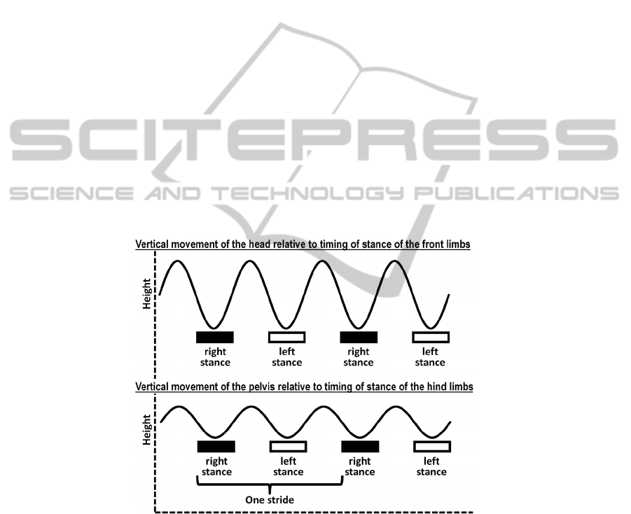
Fig. 1. Periodic signal representing normal vertical movement of the head or pelvis of horses
moving at the trot. Local minimums are reached at middle of the stance of each limb (i.e., front
limb for head movement, hind limb for pelvic movement) and local maximums occur after
stance of each limb.
Kinematic studies of normal horses and lame horses moving at the trot have
demonstrated that the head and pelvis move up and down twice during each stride.
52
Head and pelvic height reach lowest position in the middle of and highest position
after the stance phase of each diagonal pair (Figure 1) [5]; [4]; [13]. Lameness mani-
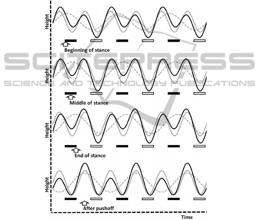
fests as perturbation of the normal sinusoidal-like vertical movement of the head and
pelvis (at twice stride frequency) by a recurring component (at 1x stride rate) (Figure
2) [13].The aim of this article is to describe this approach of objective lameness eval-
uation using wireless transmission of body mounted inertial sensors and to demon-
strate that it can be used practically in clinical cases trotting naturally over ground.
Fig. 2. Deformation of the normal vertical periodic motion of head or pelvis (gray solid line)
by a component at 1x stride rate (gray dashed line) in lame horses moving at the trot. The black
wave line represents the deformed periodic motion of a lame horse. Timing of lameness com-
ponent relative to the phase of stride (arrows) indicates affected limb and phase of stance (be-
ginning, middle, end) affected. The stances of the front limbs (if graphs represent head move-
ment) or hind limbs (if graphs represent pelvic movement) are indicated as black (right limb)
and white (left limb) rectangular figures.
53

2 Features of the Inertial Sensor-based System for Lameness De-
tection in Horses
2.1 Sensors
This device is composed of three small wireless inertial sensors each weighing 32 g
and measuring 3.2 x 3.8 x 1.9 cm. Each sensor consists of a surface-mounted,
microelectrical-mechanical device (accelerometer
1
or gyroscope
2
), radio transceiver
(open wireless technology standard) and antenna
3
, 4.2-V lithium-polymer battery
4
,
microcontroller,
5
and associated circuitry. The sensors are sampled synchronously at
200 Hz. Two of the sensors are uniaxial accelerometers, one attached to the head
(Figure 3A) and one to the pelvis (Figure 3C). A third sensor is a gyroscope attached
to the dorsal aspect of the right front distal limb (Figure 3B), measuring rotation of
the digit on the sagittal plane. Fault detection algorithms are implemented to quantify
vertical torso perturbation. This perturbation causes asymmetry of vertical torso
movement, which is measured and reported to the user.
2.2 Computer
A tablet PC equipped with a class 1 Bluetooth receiver (Figure 4) receives and stores
raw data, conducts data analysis, generates a report of the analysis, and stores the
results of data analysis.
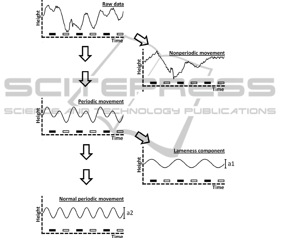
2.3 Software
Data acquisition and analysis software were custom written
6,7
to perform multiple
tasks including a moving window error correction, double integration and decomposi-
tion into periodic and random components (Figure 5). After the random component is
extracted, asymmetry of vertical torso movement (i.e., lameness) is quantified by
calculating the ratio of the amplitude of the first harmonic (a1) to the amplitude of the
second harmonic (a2) (Figure 5) and by calculating differences in local head and
pelvis maximums and minimums between right and left strides (Figure 6). Means and
standard deviations are calculated over all strides collected. Peak detection algorithms
are used to automatically select strides to be analyzed. A report is generated at the end
of data analysis (Figure 7).
__________________________
1
MMA7260QT, ± 1.5 to 6 g, Freescale Semiconductor, Austin TX, USA.
2
Gyrostar ENC-03M, Murata Electronics North America, Smyrna, GA, USA.
3
EYSF1SAJJ, Taiyo Yuden Co Ltd, Tokyo, Japan.
4
Hyper Power Co Ltd, Shenzhen, China.
5
PIC18LF452/PQ(44), Microchip Technology Inc, Chandler, AZ, USA.
6
Delphi, Borland Software Corp, Austin, Tex.
7
MATLAB, The Mathworks Inc, Natick, Mass.
54
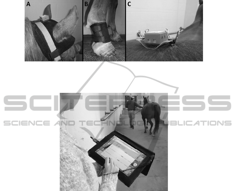
Fig. 3. Inertial sensor based system for lameness detection in horses: A and C - Vertical accel-
erometer positioned on the top of the head (poll) and top of the croup (between the sacral
tuberosities); B – Gyroscope positioned on the dorsal aspect of the pastern of the right front
limb.
Fig. 4. Data collection with the inertial sensor based system for lameness detection in horses: A
tablet PC equipped with a long-range class 9 Bluetooth receiver stores and analyses data ob-
tained by the inertial sensors.
3 Validation of the Inertial Sensor-based System for Lameness
Detection in Horses
This system has been validated by comparison with traditional kinematics using hors-
es with and without lameness trotting on the treadmill, with stationary force plate
evaluations (kinetics) and with subjective evaluation by expert veterinarians. The
inertial sensor system has shown to be precise [14], accurate [15]; [16] and more
sensitive than subjective evaluation performed by experienced veterinarians [17].
Results of evaluation with the inertial sensor system correlate with results of tradi-
55
tional kinematic evaluation [16] and, for forelimb evaluation, with the results of eval-
uation with the stationary force plate [15]. Correlation between the evaluation with
the inertial sensor system and evaluation with the stationary force plate has not been
investigated yet.
Fig. 5. Decomposition of the sinusoidal-like curves of vertical displacement signals of the head
or pelvis into periodic components and random moving average. The stances of the front limbs
(if graphs represent head movement) or hind limbs (if graphs represent pelvic movement) are
indicated as black (right limb) and white (left limb) rectangular figures under the horizontal
axis. The first periodic harmonic with frequency equal to frequency of the stride is the lame-
ness component. The second harmonic with frequency equal to twice the frequency of the
stride represents the normal vertical oscillation of the head or pelvis. Lameness severity is
proportional to the ratio between the amplitude of the lameness component and the normal
component (a1/a2).
56
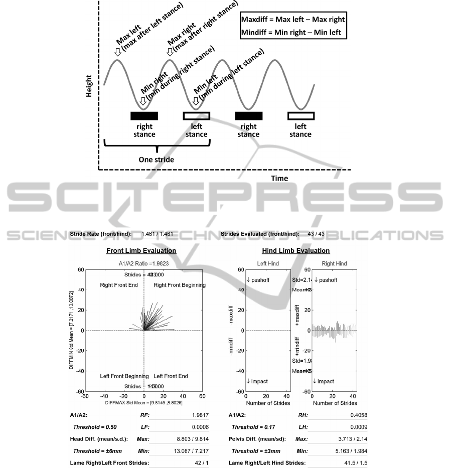
Fig. 6. Calculation of the difference between the maximal positions of the head or pelvis
(maxdiff) after the stance of each diagonal limb pair. Calculation of the difference between the
minimal positions of the head or pelvis (mindiff) during the stance of each diagonal limb pair.
Fig. 7. Report of an evaluation performed with the inertial sensor system. Results of the front
limbs are on the left side and results of the hind limbs are on the right side. Graphs and the data
reported below each graph should be considered while interpreting the results.
57

References
1. Anon: National economic cost of equine lameness, colic, and equine protozoal
myeloencephalitis in the United States. In: USDA:APHIS:VS, National Healt Monitoring
System. Information Sheet. Fort Collins. #N348 (2001) 1001
2. Arkell, M., Archer, R. M., Guitian, F. J., May, S. A.: Evidence of bias affecting the inter-
pretation of the results of local anaesthetic nerve blocks when assessing lameness in horses.
Vet. Rec. 159 (2006) 346-349
3. Baxter, G. S, Stashak, T. S.: Chapter 3 – Examination for lameness. In: T. E. Adams &
Stashak’s Lameness in Horses, 6.ed., Wiley-Blackwell, Ames (2011) 109-205
4. Buchner, H. H. F.: 10 - Gait adaptation in lameness. In: Back W, Clayton H. Equine Lo-
comotion. Saunders, London (2001) 251-279
5. Buchner H. H, Savelberg H. H., Schamhardt H. C., Barneveld A.: Head and trunk move-
ment adaptations in horses with experimentally induced fore- or hindlimb lameness. Equine
Vet. J. 28 (1996) 71-76
6. Fuller, C. J., Bladon, B. M., Driver, A. J., Barr, A. R. S.: The intra- and inter-assessor
reliability of measurement of functional outcome by lameness scoring in horses. Vet. J. 171
(2006) 281-286
7. Hewetson, M., Christley, R. M., Hunt, I. D., Voute, L. C.: Investigations of the reliability
of observational gait analysis for the assessment of lameness in horses. Vet. Rec. 158
(2006) 852-858.
8. Kaneene, J. B., Ross, W. A., Miller, R.: The Michigan equine monitoring system. II. Fre-
quencies and impact of selected health problems. Prev. Vet. Med 29 (1997) 277-292
9. Kaneps, A. J. Chapter 25 – Physical treatment of the equine athlete. In: Hinchcliff, K.W.,
Kaneps, A. J., Geor, R. J. Equine Sports Medicine and Surgery. Saunders, Edinburgh
(2004) 533-537
10. Keegan, K. G., Wilson, D. A., Wilson, D. J., Smith, B., Gaughan, E. M., Pleasant, R. S.,
Lillich, J. D., Kramer, J., Howard, R. D., Bacon-Miller, C., Davis, E. G., May, K. A.,
Cheramie, H. S., Valentino, W. L., van Harrevald, P. D.: Evaluation of mild lameness in
horses trotting on a treadmill: Agreement by clinicians and interns or residents and correla-
tion of their assessments with kinematic gait analysis. Am. J. Vet. Res. 59 (1998) 1370-
1377
11. Keegan, K. G.: Evidence-based lameness detection and quantification. Vet. Clin. Equine
Practice, 23 (2007) 403-423
12. Keegan, K. G., Dent, E. V., Wilson, D. A., Janicek, J., Kramer, J., Lacarrubba, A., Walsh,
D. M., Cassells, M. W., Esther, T. M., Schiltz, P., Frees, K. E., Wilhite, C. L., Clark, J. M.,
Pollitt, C. C., Shaw, R., Norris, T.: Repeatability of subjective evaluation of lameness in
horses. Equine Vet. J. 42 (2010) 92-97
13. Keegan, K. G.: Kinematics/Kinetics. In: T. E. Adams & Stashak’s Lameness in Horses, 6th
edn. Wiley-Blackwell, Ames, (2011) 165-172
14. Keegan, K.G., Kramer, J., Yonezawa, Y., Maki, H., Pai, P.F., Dent, E.V., Kellerman, T.E.,
Wilson, D.A., Reed, S.K. Assessment of repeatability of a wireless, inertial sensor-based
lameness evaluation system for horses. Am J Vet Res. 2011a Sep;72(9):1156-63.
15. Keegan, K.G., MacAllister, C.G., Wilson, D.A., Gedon, C.A., Kramer, J., Yonezawa, Y.,
Maki, H., Pai, P.F. Comparison of an inertial sensor system to the stationary force plate for
evaluation of horses with bilateral forelimb lameness. Am J Vet Res. Accepted 2011b.
16. Keegan, K., Wilson, D., Kramer, J., Reed, S., Yonezawa, Y., Maki, H., Pai, P., Lopes, M.
Comparison of a body-mounted inertial sensor-based method to subjective evaluation for
detection of lameness in horses. Submitted to the Equine Veterinary Journal. October
2011c.
58

17. McCracken, M., Kramer, J., Keegan, K., Lopes, M., Wilson, D., Reed, S. Comparison of an
Inertial Sensor Based System of Lameness Quantification to Subjective Lameness Evalua-
tion. Submitted to the Equine Veterinary Journal. November 2011.
18. Näsänen, R., Ojanpää, H., Tanskanen, T., Päällysaho, J.: Estimation of temporal resolution
of object identification in human vision. Exp Brain Res. 172 (2006) 464-471
19. Ross, M. W.: Chapter 2 – Lameness in horses: Basic facts before starting. In: Ross, M. W.
e Dyson, S. J. Diagnosis and Management of Lameness in the Horse, 2nd edn. Elsevier
Saunders, St. Louis (2011a) 3-8
20. Ross, M. W.: Chapter 7 – Movement. In: Ross, M. W. e Dyson, S. J. Diagnosis and Man-
agement of Lameness in the Horse, 2nd edn. Elsevier Saunders, St. Louis (2011b) 64-80
21. Sweet, A. L.: Temporal discrimination by the human eye. Am. J. Psych. 66 (1953) 185
22. Todd, J. J., Marois, R.: Capacity limit of visual short-term memory in human posterior
parietal cortex. Nature. 428 (2004) 751-754
23. Trenti, E. J., Barraza, J. F., Eckstein, M. P.: Learning motion: human vs. optimal Bayesian
learner. Vision Res. 50 (2010) 460-472
59
