
MINIMALISTIC VISION-BASED COGNITIVE SLAM
M´ario Saleiro, J. M. F. Rodrigues and J. M. H. du Buf
Vision Laboratory, LARSyS, University of the Algarve (ISE and FCT), Campus de Gambelas, 8005-139 Faro, Portugal
Keywords:
Robotics, SLAM, Navigation, Memory.
Abstract:
The interest in cognitive robotics is still increasing, a major goal being to create a system which can adapt
to dynamic environments and which can learn from its own experiences. We present a new cognitive SLAM
architecture, but one which is minimalistic in terms of sensors and memory. It employs only one camera with
pan and tilt control and three memories, without additional sensors nor any odometry. Short-term memory is
an egocentric map which holds information at close range at the actual robot position. Long-term memory is
used for mapping the environment and registration of encountered objects. Object memory holds features of
learned objects which are used as navigation landmarks and task targets. Saliency maps are used to sequen-
tially focus important areas for object and obstacle detection, but also for selecting directions of movements.
Reinforcement learning is used to consolidate or enfeeble environmental information in long-term memory.
The system is able to achieve complex tasks by executing sequences of visuomotor actions, decisions being
taken by goal-detection and goal-completion tasks. Experimental results show that the system is capable of
executing tasks like localizing specific objects while building a map, after which it manages to return to the
start position even when new obstacles have appeared.
1 INTRODUCTION
Autonomous mobile robots must be able to learn and
interact with dynamic environments in which they
navigate. Many explored approaches are based on tra-
ditional algorithms from artificial intelligence. They
employ perceptions of the surrounding environment
which are based on precise data from distance sensors
(infrared, ultrasonic, laser) in combination with pre-
cise odometry for navigation. They may allow robots
to perform simple tasks in controlled environments,
but are less appropriate for highly dynamic and com-
plex environments (Ratanaswasd et al., 2005). The
latter require flexible and adaptive systems, i.e., cog-
nitive ones like our brain. However, also many lower
animals like mice and crows are experts in mastering
complex tasks in dynamic environments.
Egocentric navigation using a predefined map but
without precise metrics can be achieved by a cogni-
tive robot (Kawamura et al., 2002). This robot fea-
tured a memory system split into short- and long-term
ones, and it employed a simple vision system to detect
colored tags which are used as references. However,
it was not used for SLAM (simultaneous localization
and mapping) because the map was predefined. An-
other robot (Meger et al., 2008) employed a more so-
phisticated vision system, combining saliency, object
recognition and stereo vision along with a laser sen-
sor for navigation and mapping. RatSLAM (Milford
and Wyeth, 2010) is a navigation and mapping sys-
tem which relies on goal-oriented navigation and on
biologically inspired SLAM. Another biologically in-
spired navigation system consists of an implementa-
tion of a particular path-integration model, i.e., mod-
ified continuous-time recurrent neural networks (Pa-
pauschek and Zillich, 2010). A cognitive architecture
can also be based on biologically inspired multiple
memory systems, involving episodic, semantic, pro-
cedural and working memory units (Kleinmann and
Mertsching, 2011).
In this paper we present a cognitive framework for
robots composed of four interactive systems: vision,
memory, SLAM and task management. The major
contributions are: (a) the implemented SLAM system
is directly integrated with the short- and long-term
memories and affected by time, allowing the robot
to adapt to dynamic environments by means of re-
inforcement learning, (b) the implemented task man-
agement and task building system is based on a hierar-
chy of only three basic actions, (c) only one camera is
employed for vision and no other sensors nor odom-
etry is used, and (d) vision is steered by saliency for
Focus-of-Attention and object recognition.
The rest of this paper is organised as follows. In
614
Saleiro M., M. F. Rodrigues J. and M. H. du Buf J..
MINIMALISTIC VISION-BASED COGNITIVE SLAM.
DOI: 10.5220/0003881306140623
In Proceedings of the 4th International Conference on Agents and Artificial Intelligence (SSIR-2012), pages 614-623
ISBN: 978-989-8425-95-9
Copyright
c
2012 SCITEPRESS (Science and Technology Publications, Lda.)

Section 2 we present the cognitive robot framework,
including the vision, task manager and localisation
and mapping modules. In Section 3 we present re-
sults, and in Section 4 a final discussion.
2 COGNITIVE ROBOT
FRAMEWORK
Cognition generally refers to the faculty of mental ac-
tivities of humans and certain animals dealing with
abstractions of information from the real world, their
representations in memory, as well as automatic re-
call (Patnaik, 2007). Cognition may provide a solu-
tion to overcome the limitations of AI, allowing us
to create cognitive robots that can execute new tasks
by combining knowledge gathered in previous expe-
riences and emotions (Ratanaswasd et al., 2005).
Through cognition, the human brain is able to ac-
quire and process perceptionsof the surroundingenvi-
ronment in a very fast and efficient way. Such percep-
tions consist of complex information captured using
our sensory systems, notably our visual system which
collects the most important information for naviga-
tion. In contrast to precise sensor systems in tradi-
tional robotics, our visual system allows us to recog-
nize objects and to know whether they are near or far,
but it does not provide us with very precise distances.
Another important feature of the human brain is
the close connection between sensory systems and
memory. This close connection also works as a filter:
some of the information acquired remains in memory
for a long time, whereas other information may be
instantly discarded or kept for a brief time. This dual-
ity in information storage has been studied in cogni-
tive psychology for many decades, which resulted in
the assumption of two major types of memory: short-
term memory (STM) and long-term memory (LTM)
(Patnaik, 2007). In this memory structure, only the
most important information flows from STM to LTM,
the importance of the information being affected by
attention and concentration. Although most informa-
tion may be discarded, the human brain can store a
higher level of detail if necessory (Brady et al., 2008).
In the same way that the brain can select which in-
formation should be stored, the visual system can se-
lect which areas of the surrounding environment de-
serve most attention based on the saliency of those
areas (Itti et al., 1998). This information-filtering
process is also very important because otherwise the
brain would always be busy processing all the in-
formation gathered by our senses (Rensink, 2000).
After selecting which areas deserve most attention,
the brain processes those areas for object recognition,
comparing the objects seen with normalized tem-
plates previously stored in memory (Rodrigues and
du Buf, 2009).
Another feature of human cognition is to plan
and execute sequences of actions for accomplishing
a goal, even sequences which have never been done
before. This property is closely related to learning,
because we can deduce new sequences by combining
actions which we have done or seen before (Meinert,
2008).
The implementation of a cognitive system may
lead to a new generation of robots which can adapt to
dynamic environments and can interact with humans.
There have already been some developments. The
most relevant ones use vision as the main source of
information, a memory system composed of STM and
LTM, and an egocentric navigation system (Kawa-
mura et al., 2002). Stereo vision is also possible
(Meger et al., 2008). In addition to memory and vi-
sual systems which differ from those used in tradi-
tional robotics, a cognitive robot also needs SLAM
capability, but one which, unlike traditional SLAM,
is not based on large amounts of data from precise
range sensors and precise odometry systems (Monte-
merlo et al., 2002).
In the following sections we describe an architec-
ture for a cognitive robot comprising a complex vi-
sual system, with Focus-of-Attention (FoA) and ob-
ject recognition, a memory system with STM and
LTM, and a task management system. This architec-
ture is closely integrated with the SLAM system.
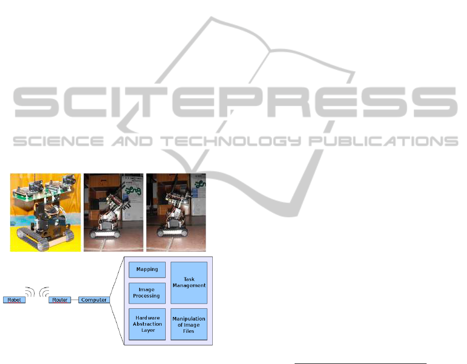
2.1 Robotic Platform
The cognitive system was implemented and tested us-
ing a small Surveyor SRV-1 robot with an SVS stereo
vision system mounted on a pan and tilt structure, but
only one camera was used (Fig. 1 top-left). The robot
also features differential steering and a Wi-Fi connec-
tion. The robot’s command protocol allows to receive
camera images on a remote computer for processing
them, and to send back commands to move the robot
and the robot’s head.
Since the robot does not have any odometry sys-
tem, it is impossible to get precise travel distances and
rotation angles. All movements are controlled by tim-
ing, e.g., move forward during 1 second. This only
yields approximate distance and rotation values. Al-
though it makes navigation and mapping more diffi-
cult, it actually serves our goal because we want to
make a cognitive system which does not require pre-
cise distances for navigation and mapping.
Regarding the movement of the head, we only
used two tilt positions T1 and T2 (Fig. 1 top-center
MINIMALISTIC VISION-BASED COGNITIVE SLAM
615
and top-right) and five pan positions: two to the left,
one in front, and two to the right (Fig. 5). T1 is used
to inspect the near surrounding whereas T2 serves to
visualize the more distant environment. The devel-
oped software architecture is modular, each module
corresponding to one component of the robot’s sys-
tem, although they are all interdependent. We also
used two open source libraries: OpenSURF (Evans,
2009) for object recognition, and NMPT (Nick’s Ma-
chine Perception Toolbox) (Butko et al., 2008) to gen-
erate saliency maps.
Figure 1 (bottom) shows the main modules. (a)
The hardware abstraction layer consists of a library of
functions to initialize and close the connection to the
robot, to realize motor actions, to request images and
to change the configuration of the robot. (b) Manip-
ulation of Image Files contains functions to perform
basic operations of opening and saving image files.
(c) Image Processing contains all functions necessary
for the detection and recognition operations. (d) Task
Management consists of a central agent which sched-
ules and plans tasks to be accomplished. (e) Mapping
contains all functions for robot localization and for
mapping the environment.
Figure 1: Top, from left: SRV-1 robot with head tilts T1 and
T2. Bottom: software layers.
Because of the robot’s small size, it was tested in a
specially preparedsandbox of 3×3.5 m. The sandbox
is delimited by green tape on the floor, and objects
like tool boxes were placed on or just beyond the tape
at various positions. The green delimiting tape can
easily be replaced by an algorithm for navigating in
corridors (Jos´e et al., 2010).
2.2 Saliency and Active Vision
The system was configured such that captured frames
I(x,y) havea size of M×N = 320×240 pixels with R,
G and B components. Instead of processing the entire
images, we applied a saliency algorithm to select the
image regions which may contain the most important
information. Each selected region is then processed
for obstacle and object recognition. To this purpose
the regions are delimited and sorted in decreasing
order of saliency, which mimics sequential process-
ing by Focus-of-Attention (FoA) with Inhibition-of-
Return (IoR) to already analyzed regions. This pro-
cess consists of the following three steps:
(1) We apply the Fast Saliency algorithm (Butko
et al., 2008) to create a saliencymap I
s
(x,y); see Fig. 2
(top-right). Fast Saliency applies a spatial Difference-
of-Gaussian filter to the intensity component(R+G+
B)/3, but its temporal filter is not used because we
have “still” images.
(2) The saliency map is analyzed for the detection
and selection of the regions, discarding regions which
are too small to contain useful information. The map
I
s
(x,y) is divided into non-overlapping regions of size
4× 4, and in each region we count the number of pix-
els N
s
with a saliency value bigger than Θ
1
, where Θ
1
is 50% of the maximum saliency value in I
s
. If N
s
is
smaller than a threshold value Θ
2
, where Θ
2
is 60% of
the number of pixels in the region (10 in case 4× 4),
the region is discarded and blackened in I
s
.
Figure 2 (2nd row left) shows the processed I
s
.
Because of the 4 × 4 blocks the resulting image is
reduced to M/4 × N/4 pixels, which speeds up sub-
sequent processing. Then, to delimit each region, we
apply a fast blob detection algorithm (Saleiro et al.,
2009). The blobs are expanded to their bounding
rectangle, and all rectangles with a size smaller than
Θ
3
= 300 pixels are discarded. This results in image
I
sr
as shown on the 2nd row, at right, in Fig. 2.
(c) For implementingcovertattention, all resulting
regions of size p × q are characterized and sorted in
descending order by using their average saliency,
N
e
φ
=
∑
k∈[0,p−1],l∈[0,q−1]
I
s
(x+ k, y+ l)
p× q
, (1)
see Fig. 2 (3rd row), for processing them for obsta-
cle detection and object recognition using Inhibition-
of-Return (IoR). Figure 2 (bottom) illustrates this se-
quential process, the arrows showing the processing
order. The above process mimics human Focus-of-
Attention (FoA), and it is only applied to images cap-
tured using camera tilt T2, when the robot can see
farther away. The use of saliency, when integrated
with motor actions, results in active vision: naviga-
tion decisions and head movements are completely
controlled by sequential FoA with IoR in combina-
tion with recognized objects.
ICAART 2012 - International Conference on Agents and Artificial Intelligence
616
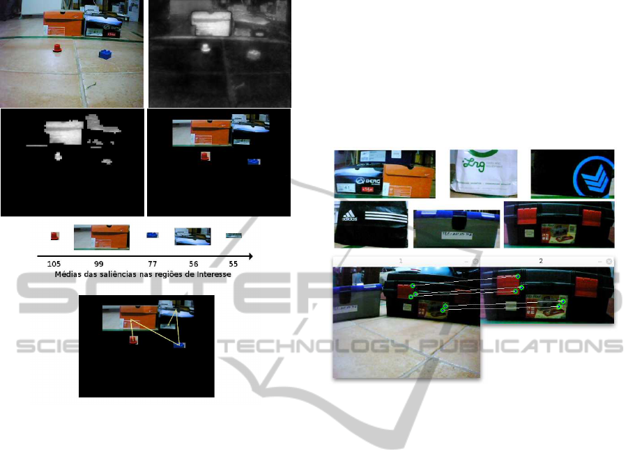
Figure 2: Top: captured image and its saliency map. Second
row: saliency map after filtering and rectangular regions of
interest. Third row: the regions sorted by saliency. Bottom:
sequential order of FoA.
2.3 Object Recognition
As mentioned before, we use the OpenSURF library
(Evans, 2009) to recognize objects. Like we, humans,
store normalized images of many objects in memory
(Rodrigues and du Buf, 2009), the robot also needs to
memorize one or more views (templates) of the ob-
jects which will serve as navigation landmarks and
task targets. The top two rows in Fig. 3 show exam-
ples. All images stored in memory were taken with
an object distance of about 45 cm. This allows, after
object recognition, the robot to estimate its distance
to the object by comparing the dimensions of the rec-
ognized object in the captured image with those of the
stored template.
Before the robot starts navigating, all stored tem-
plates are processed by SURF’s keypoint algorithm
for creating the keypoint arrays for a fast object
matching during a task’s execution. These keypoint
arrays are similar to the spatial keypoint maps which
we ourselves store in memory (Rodrigues and du Buf,
2009). During navigation, when a region with high
saliency must be analyzed, the region’s keypoint ar-
ray is determined by SURF. This array is matched
against all stored object arrays, and if there are at
least three matching keypoints an object is recog-
nized. This process employs some relaxation of
the distances between keypoints in order to obtain
viewpoint-invariance – a similar process called dy-
namic routing may occur in our brain (Rodrigues and
du Buf, 2009). The bottom row in Fig. 3 illustrates
object recognition with illumination- and viewpoint-
invariance.
Figure 3: Top two rows: examples of learned objects. Bot-
tom: example of object recognition with 5 matching key-
points.
2.4 Task Management
The task managementsystem allows the robot to build
and execute complex tasks from simpler ones. A
central agent is responsible for building and organiz-
ing the tasks in order to accomplish a requested goal
(Ratanaswasd et al., 2005; Alami et al., 2006). Only
two levels of tasks exist. Micro-tasks are atomic ac-
tions like “go forward” and “turn right.” Macro-tasks
are more complex. They are built from the aggrega-
tion of micro-tasks and simple macro-tasks. The sim-
ple macro-tasks are pre-programmed, but always as-
sociated with simple actions like “search” and “return
home.” When the robot is given more than one gen-
eral (top) task, it places them in a task buffer for their
sequential – but also concurrent – execution.
Each macro-task consists of three blocks: (a) a vi-
suomotor action cycle consists of movements to be
made according to newly captured visual information;
(b) the objective detection function serves to detect
the actual, requested goal; and (c) the condition for
task conclusion function tracks whether a task has
been completed or not.
The block structure is hierarchical: the three
above blocks can each be split into sub-blocks, using
the same block structure. This hierarchical and dy-
MINIMALISTIC VISION-BASED COGNITIVE SLAM
617
namic structure enables concurrent execution of mul-
tiple tasks. However, since there is always one main
task, only one visuomotor cycle can be active at any
time, during which all other visuomotor cycles remain
inactive. Nevertheless, while one visuomotor cycle
(a) is being executed, the two detection functions (b)
and (c) related to other tasks are still evaluated. When
a task is completed, its blocks are deactivated and
the next task’s visuomotor cycle is activated. This
process is repeated until all pending tasks are com-
pleted. Concurrent task processing is implemented by
using three separate block buffers: one for visuomotor
blocks, one for objective detection blocks, and one for
objective conclusion condition blocks. The blocks in
the last two buffers are executed sequentially within
each visuomotor block which controls the robot. The
visuomotor blocks are always the most complex ones,
since the other two types only consist of simple detec-
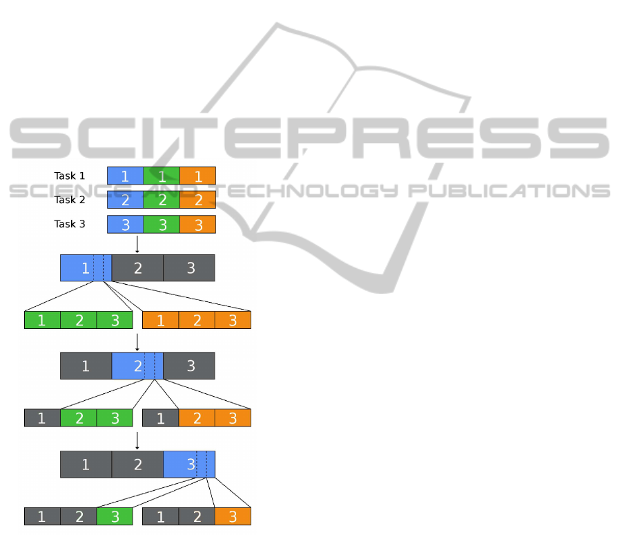
tion functions. Figure 4 illustrates the task building
process.
Figure 4: Three macro-tasks are concurrently executed by
sequences of simple macro-tasks and micro-tasks. Blue: vi-
suomotor blocks. Green: objective detection blocks. Or-
ange: objective conclusion condition blocks. The grey
blocks are inactive.
For the robot’s navigation, we considered only
two fundamental modes: (a) the exploration mode is
used to navigate in an unknown environment, and (b)
in the excursion mode the robot uses gathered infor-
mation to move itself in a more efficient way. These
modes are detailed below.
2.4.1 Exploration Mode
In this navigation mode the robot takes decisions ac-
cording to saliency. It simply moves towards regions
where the probability of finding important informa-
tion is higher. Below, all newly acquired images are
processed, using saliency-based regions and SURF
for object and obstacle detection as explained in Sec-
tions 2.2 and 2.3. The robot then takes decisions, also
on the basis of saliency but of bigger image regions,
to look more to the left or more to the right. We first
explain head (pan) control for looking left and right,
and then wheel control for actually moving the robot.
For head (pan) control, the robot initially looks
ahead with tilt position T2, and captures one (frontal)
image. It splits this into equally-sized regions: left,
center and right. It calculates the average saliency
values in the left and right regions. If one value, for
example that of the left region, is higher than a thresh-
old value T
s
, with T
s
equal to 15% of the maximum
saliency S
max
in the entire (frontal) image, the robot
will change the pan angle and capture an image which
is left to the frontal one. If both values are higher than
the threshold, it will capture two images, one to the
left and one to the right of the frontal one, but it will
look first to the side with the higher average saliency
value.
If the robot decided to look to the left, the average
saliency of the left third of the new image is com-
puted. If the value is higher than 15% of the maxi-
mum value in the entire image, it will decide to look
even more to the left and capture a new image with
a more oblique pan angle. This image is processed
again for object recognition, but not further split be-
cause the maximum pan angle has been reached. If
the robot decided to (also) look to the right, the pro-
cedure is the same, but the right third of the captured
image right to the frontal one is used for deciding to
turn the pan angle even more to the right. Hence, the
robot may capture only the frontal image, plus one or
two to the left, plus one or two to the right, so it may
capture at most five images (Fig. 5), but the above
procedure is only applied for controlling the head’s
pan angles and object recognition at the robot’s actual
position.
The next step concerns wheel control: to decide
to move left, straight ahead, or right. This is also con-
trolled by average saliency values of parts of the cap-
tured images, but only of three big parts as shown by
the differently shaded regions in Fig. 5. If some of the
at most five images were not captured, for example
when the robot decided to look only in front and a bit
to the right (2 images), the missing images (5−2 = 3)
are assumed to have zero saliency. The average sali-
ICAART 2012 - International Conference on Agents and Artificial Intelligence
618
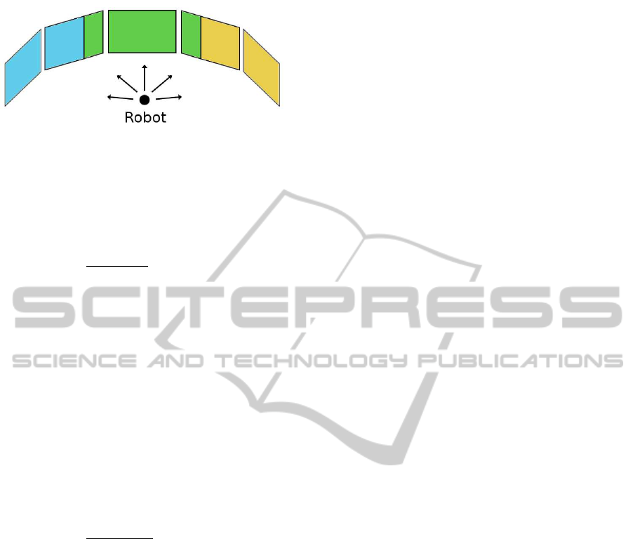
Figure 5: For head (pan) control, the robot will capture at
least the frontal (center) image, but it can capture at most
five images. For wheel control, average saliency in the three
shaded regions is used to move left, straight ahead, or right.
ency values of the three regions, left (s
l
), front (s
f
)
and right(s
r
) are computed, and then their relative val-
ues
s
x
r
=
s
x
s
l
+ s
f
+ s
r
, x ∈ {l, f,r}. (2)
However, instead of only using max(s
x
r
) as a decision
criterion, the distance to its previous positions and to
already detected reference objects are also important,
so that the robot does not return to already explored
regions. If a reference object has already been found,
the robot calculates the approximate distances, d
l
, d
f
and d
r
, between that object and each of the three po-
sitions were the robot may move next: e.g. 25 cm to
the left of the actual position if it moves to the left,
but also 25 cm forward and to the right. In case no
reference object has been found, it calculates the dis-
tance to the third last position where it has been. Once
having the distances, the relative distances are deter-
mined by
d
x
r
=
d
x
d
l
+ d
f
+ d
r
, x ∈ {l, f,r} (3)
and the probabilities of moving left, forward and
right are obtained by combining relative distances and
saliencies
P
x
= (1 − k)d
x
r
+ ks
x
r
, x ∈ {l,r} (4)
P
f
= w{ (1 − k)d
f
r
+ ks
f
r
}, (5)
and maxP
x
, x ∈ {l, f,r} is selected. Parameter k ∈
[0,1] is used to balance or emphasize saliency and dis-
tance. In Eq. 5 the w parameter allows to bias forward
movements or left/right ones. Optimal parameters,
empirically determined, are k = 0.25 and w = 1.65.
After selecting the direction, the robot checks for an
obstacle there. If there is none, it moves in that direc-
tion. Otherwise, it will check in the direction with the
next lower probability and may move there, etc.
2.4.2 Excursion Mode
This navigation mode is much simpler than the explo-
ration mode, because the robot can rely on its map
constructed in exploration mode, it already knows lo-
cations of some reference objects, and it has its past
experiences in memory. The latter means that it keeps
a buffer with its last 10 positions in the map, and
also one with the sequential order in which objects
were recognized. These experiencies allow the robot
to follow the inverse path established in exploration
mode. If it encounters any new obstacle on the path,
it checks both sides for open space and it turns to the
side which has the smallest distance to the final desti-
nation. When there are no more obstacles, it resumes
the original (inverse) path.
2.5 Detection of Obstacles and Limits
As mentioned before, we only use one of the robot’s
cameras and two tilt positions T1 and T2: T2 is used
for global navigation and object recognition, whereas
T1 serves detection of obstacles and sandbox lim-
its at close range. After detection, the robot esti-
mates approximate distances by using an interpola-
tion function, which relates each line of the image to
a distance. Some simple geometry also allows to ap-
proximate relative angles. This information is used
to place detected obstacles and sandbox limits in the
maps. Only two maps are used: (a) a small but high-
precision map (STM) and (b) a big but low-precision
map (LTM). The first one is used for immediate deci-
sions; the second for global navigation and more com-
plex tasks.
To detect the green tape that delimits the sandbox,
the RGB image is converted to HSV color space and a
simple color segmentation is applied. To detect obsta-
cles we use the I
sf
maps and suppress regions which
correspond to the green tape, such that only salient
objects remain. Figure 6 illustrates obstacle detec-
tion. The top shows the captured image I with green
tape and an obstacle. The 2nd row shows the seg-
mented green tape I
f f
at left, and the saliency map I
sf
at right. The 3rd row shows the saliency map with the
green tape suppressed (I
of
at left) and after filtering to
remove small regions (I
o
at right).
2.6 Memory and Mapping
Building a map of the environment is fundamental
for navigation and localization. As mentioned be-
fore, we use two types of memory: STM and LTM.
STM consists of a small map in which information at
close range like delimiting tape and obstacles is regis-
tered. Therefore, this map is used in conjunction with
head tilt position T1. The STM map is egocentric and
only used at an actual position of the robot. Whenever
non-black pixels are found in images I
f f
and I
of
, T1-
MINIMALISTIC VISION-BASED COGNITIVE SLAM
619
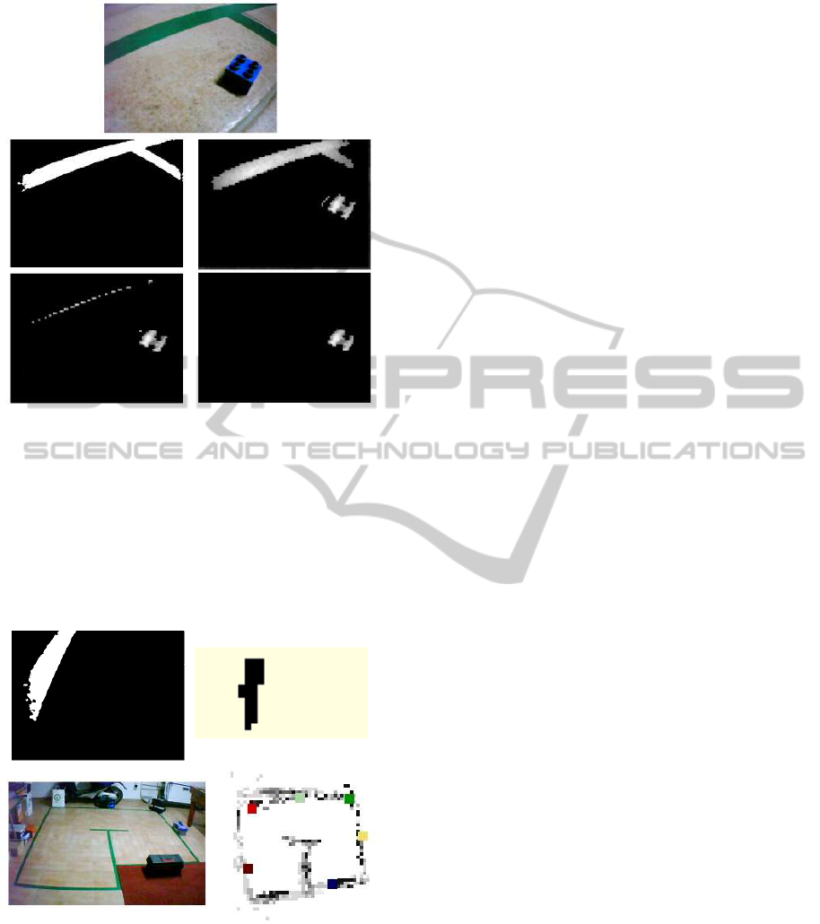
Figure 6: Obstacle detection process. See text.
calibrated image line-distance interpolation functions
are used to estimate the pixels’ positions relative to
the robot. These positions are stored in STM together
with object types like green tape. The size of STM is
the same as that of I
of
. Figure 7 (top-right) shows an
example of STM in the case of green tape, i.e., in the
horizontal plane after perspective-view correction of
the segmented image to the left.
Figure 7: Examples of memory maps. Top-left: binary im-
age (tilt T1) with segmented green tape. Top-right: resulting
(x,y) Cartesian STM map when looking forward. Bottom:
picture of the robot’s sandbox and a built LTM map after
completing a SLAM task. Reference objects are marked by
colored squares.
LTM is a bigger map, with lower resolution, for
global navigation. Unlike STM, LTM is not a binary
map because object labels must be stored at certain
positions. LTM is built with positive and negative re-
inforcements: (a) if an object is repeatedly detected
at the same position, it is positively reinforced with
a value P
R
= 40, until a maximum value M
R
= 200
is reached; (b) if a previously detected object is not
found at the same position, it is negatively reinforced
with N
R
= −40. (c) there is also a negative rein-
forcement over time. Objects which have reached
M
R
= 200 are assumed to be fixed and stable, but all
other ones are “feebled” by N
R
= −20 after every time
interval of 300 s. The latter process allowsthe robot to
“forget” inconsistent information. In Figs 7 (bottom-
right) and 8 (right column) the actual values – after
completing a task – are coded by the level of gray,
black corresponding to M
R
= 200.
Reinforcement serves to annotate objects in LTM
with a degree of certainty, i.e., whether detected ob-
jects were registered more times at the same position.
Since images captured with tilt T1 have a higher pre-
cision than those with T2, reinforcement values in
case of T1 are 3 times bigger than those in case of T2
(the latter are ±40 as mentioned above). The moment
when a pixel of the STM map is updated is registered
by assigning it a time stamp. The same applies to spa-
tial information in LTM, but not to registered objects.
Besides storing information about obstacles and
sandbox limits, the robot also keeps a list of refer-
ence objects it encountered along its path. These ob-
jects must be part of the known object library. Every
time the robot detects a known object (with tilt T2),
it calculates its approximate distance, comparing the
diagonal of the bounding box with that of the learned
object (learning was done at a distance of 45 cm). The
approximate distance but also the angle (object posi-
tion in the T2 image and pan angle of the head) are
used to store the object’s label in LTM relative to the
robot’s actual position and heading direction. After
detecting and storing an object for the first time, from
then on that object will be used to re-calibrate the
robot’s position when it is detected again. In order
to re-calibrate the robot’s heading direction, at least
two known objects must be visible in one or more of
the images as indicated in Fig. 5. The re-calibration
of position and heading direction is necessary to cor-
rect accumulated errors during navigation, a more fre-
quent recognition of known objects leading to a better
precision.
3 RESULTS
The performance of the system was assessed with five
tests with a different purpose and complexity: (1) lo-
cate an object in an unknown environment; (2) as (1)
ICAART 2012 - International Conference on Agents and Artificial Intelligence
620
but with different start and object positions; (3) lo-
cate an object in an unknown environment and return
to the start position; (4) as (3) but with a new obsta-
cle while returning; and (5) locate an object in an un-
known environment, count 4 objects and return to the
start position. All remote processing was done in real-
time, using a laptop with an Intel Core2 Duo 1.3GHz
processor and 4GB of DDR3 memory.
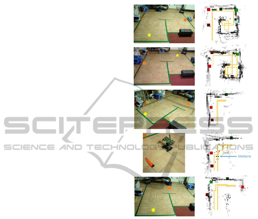
The goal of the first task was to test SLAM in ex-
ploration mode. The robot had to find a grey-blue
toolbox. The robot started at the position marked by
the yellow dot in Fig. 8 (top-left), where the orange
dot marks the position of the toolbox. Task comple-
tion took 9 minutes and 21 seconds, during which the
robot built the map shown in Fig. 8 (top-right). Each
colored square in the map is a recognized object. Al-
though the goal was accomplished, the robot recog-
nized the toolbox only the third time it was encoun-
tered. This is due to the OpenSURF algorithm, which
does not work very well for untextured objects. How-
ever, all other objects were detected and recognized
several times. We may therefore conclude that SLAM
in exploration mode worked well.
The second task equalled the first one, but with
a different target object and a different start position;
see the second line in Fig. 8. The task was accom-
plished in 10 minutes and 19 seconds, but again with
some difficulties in recognizing untextured objects.
With the third task we wanted to also test naviga-
tion in an already known environment, by first build-
ing a map while localizing a target object and then re-
questing the robot to return to the start position. This
task was executed significantly faster, in only 4 min-
utes and 8 seconds, because of the shorter path. As
in the previous tasks, the robot started by building the
map while searching for the object. Once found, it
searched for the objects it had already encountered
and returned, from object to object, until it reached the
start position. As shown in Fig. 8 (3rd row), the return
path is parallel to the forward path, which means that
the established map, saliency-based FoA and position
re-calibration are very reliable.
The fourth task was equal to the third one, but
with an unexpected obstacle on the return path; see
Fig. 8 (4th row). Task completion took a bit longer,
5 minutes and 2 seconds, because of the obstacle. In
contrast to the return path which was parallel to the
forward path in the third task, now the return path was
not parallel. The reason is that both the object marked
by the bright red square and the obstacle cause regions
with a high saliency, and the robot decided to move in
the direction of the obstacle. At close range it decided
to go between the object and the obstacle, avoiding
both.
Figure 8: Top to bottom: results of tests 1 to 5. The yellow
dots in the pictures are starting points, the orange dots are
target objects. The robot’s trajectory is shown by orange
lines in the maps.
In the final task we wanted to test the task man-
agement system. The robot was given three tasks: (a)
find an object, (b) count four objects, and (c) return to
the starting point. Each task has its own visuomotor
block, and only one of these is executed at any time,
but during each visuomotor block the detection and
verification functions of all three tasks are evaluated.
This last test was also successfully accomplished. The
robot started by trying to find the requested object,
and everytime it found an object it incremented the
object counter. After finding the requested object it
still had to find a fourth one, so it continued by going
forward. After finding the fourth object, it returned to
the starting point, “visiting” the known objects in re-
versed order. The created map is shown at the bottom
of Fig. 8.
MINIMALISTIC VISION-BASED COGNITIVE SLAM
621

4 CONCLUSIONS
We presented a cognitive robot architecture for
SLAM which integrates active vision, dual memory
and hierarchical task management. The main contri-
butions are: (a) visual saliency is used for FoA and
object recognition; (b) SLAM is directly integrated
with short- and long-term memory and affected by
time, allowing the robot to filter important informa-
tion and adapt to changes in the environment; and (c)
the task management system can build complex tasks
from simpler ones.
Regarding vision, we verified that the use of
saliency and object recognition yields a more robust
exploration, navigation also being more robust. How-
ever, monocular vision with simple solutions for dis-
tance estimation is not very precise. Therefore, a bi-
ological model for stereo disparity (Farrajota et al.,
2011) is being integrated. In addition, since object
recognition using OpenSURF is not very robust in
case of untextured objects, OpenSURF is being sub-
stituted by a biological model for multi-scale keypoint
extraction (Rodrigues and du Buf, 2006), and supple-
mented by a biological model for multi-scale line and
edge extraction (Rodrigues and du Buf, 2009). The
biological keypoint model can also supplement Fast
Saliency (Butko et al., 2008), because it adds local
image complexity to color contrast, for obtaining a
better model for FoA (Rodrigues and du Buf, 2006).
The addition of such biological models leads to a vi-
sion model which resembles the human visual system.
The system was successfully tested by using a
rather small environment, i.e., a sandbox of 3× 3.5 m,
with objects on the floor, mainly because of the
small robot platform with limited battery capacity and
speed, and a footprint of 11 × 13 cm. For testing the
system in real environments like corridors and lab-
oratory spaces, it is being mounted on a faster plat-
form with a larger battery capacity and a bigger foot-
print, but still only using a stereo camera without any
other sensors nor odometry, the camera head being
mounted on a rod with a height of about 80 cm. These
modifications allow us to test the system with also ob-
jects attached to walls and on tables, but this also re-
quires implementing and dealing with 3D egocentric
and environment maps.
ACKNOWLEDGEMENTS
This work was partially supported by the Portuguese
Foundation for Science and Technology (FCT)
project PEst-OE/EEI/LA0009/2011, EC project Neu-
ralDynamics (NeFP7-ICT-2009-6 PN: 270247), FCT
project Blavigator (RIPD/ADA/109690/2009) and by
PhD FCT grant SFRH/BD/71831/2010.
REFERENCES
Alami, R., Clodic, A., Montreuil, V., Sisbot, E. A., and
Chatila, R. (2006). Toward human-aware robot task
planning. Association for the Advancement of Artifi-
cial Intelligence Spring Symposia, AAAI, page 8pp.
Brady, T., Konkle, T., Alvarez, G., and Oliva, A. (2008).
Visual long-term memory has a massive storage ca-
pacity for object details. Proc. Nat. Acad. Scie.,
105(38):14325–14329.
Butko, N., Zhang, L., Cottrell, G., and Movellan, J. (2008).
Visual salience model for robot cameras. Proc. 2008
IEEE. Int. Conf. on Rob. and Automation, pages 2398–
2403.
Evans, C. (2009). Notes on the OpenSURF Library.
Tech. Rep. CSTR-09-001. University of Bristol. URL
http://www.chrisevansdev.com.
Farrajota, M., Martins, J., Rodrigues, J., and du Buf, J.
(2011). Disparity energy model with keypoint dispar-
ity validation. Accepted for 17th Portuguese Conf. on
Pattern Recognition, Porto, Portugal.
Itti, L., Koch, C., and Niebur, E. (1998). A model of
saliency-based visual attention for rapid scene anal-
ysis. IEEE Trans. on Patt. Recog. and Mach. Intell.,
20(11):1254–1259.
Jos´e, J., Farrajota, M., Rodrigues, J., and du Buf, J. (2010).
A vision system for detecting paths and moving osta-
cles for the blind. Proc. Int. Conf. on Software De-
velopment for Enhancing Accessibility and Fighting
Info-exclusion, pages 175–182.
Kawamura, K., Koku, A., Wilkes, D., Peters II, R., and Sek-
men, A. (2002). Toward egocentric navigation. Int. J.
Robotics and Automation, 17(4):135–145.
Kleinmann, L. and Mertsching, B. (2011). Learning to
adapt: Cognitive architecture based on biologically
inspired memory. In Industrial Electronics and Appli-
cations (ICIEA), 2011 6th IEEE Conference on, pages
936 –941.
Meger, D., Forss´en, P., Lai, K., Helmer, S., McCann, S.,
Southey, T., Baumann, M., Little, J. J., and Lowe,
D. G. (2008). Curious George: An attentive seman-
tic robot. Rob. Aut. Sys., 56(6):503–511.
Meinert, P. (2008). The impact of previous life experience
on cognitive structure changes and knowledge acqui-
sition of nursing theory and clinical skills in nontradi-
tional nursing students. PhD Thesis, Kent State Univ.,
College of Education, Health and Human Services,
USA, page 173.
Milford, M. and Wyeth, G. (2010). Persistent navigation
and mapping using a biologically inspired slam sys-
tem. Int. J. Robotics Res., 29(9):1131–1153.
Montemerlo, M., Thrun, S., Koller, D., and Wegbreit, B.
(2002). Fastslam: A factored solution to the simulta-
neous localization and mapping problem. Proc. AAAI.
Nat. Conf. Art. Int., pages 593–598.
ICAART 2012 - International Conference on Agents and Artificial Intelligence
622

Papauschek, C. and Zillich, M. (2010). Biologically in-
spired navigation on a mobile robot. In IEEE Int.
Conf. Robotics and Biomimetics, pages 519 –524.
Patnaik, S. (2007). Robot Cognition and Navigation: An
Experiment with Mobile Robots. Springer, 1st edition.
Ratanaswasd, P., Gordon, S., and Dodd, W. (2005). Cogni-
tive control for robot task execution. Proc. IEEE Int.
Work. Rob. Hum. Int. Com., (5):440–445.
Rensink, R. (2000). The dynamic representation of scenes.
Visual Cogn., 7(1-3):17–42.
Rodrigues, J. and du Buf, J. (2006). Multi-scale keypoints
in V1 and beyond: object segregation, scale selection,
saliency maps and face detection. BioSystems, pages
75–90.
Rodrigues, J. and du Buf, J. M. H. (2009). Multi-scale
lines and edges in V1 and beyond: Brightness, ob-
ject categorization and recognition, and conscious-
ness. Biosystems, 95(3):206–226.
Saleiro, M., Rodrigues, J., and du Buf, J. (2009). Auto-
matic hand or head gesture interface for individuals
with motor impairments, senior citizens and young
children. Proc. Int. Conf. Soft. Dev. for Enhancing
Accessibility and Fighting Info-Exclusion, pages 165–
171.
MINIMALISTIC VISION-BASED COGNITIVE SLAM
623
