
MANDIBLE PARAMETERIZATION USING A REFERENCE
LINE
M. J. Tsai
1
, C. L. Chen
2
, H. W. Lee
1
, C. H. Chao
3
and P. W. Hsu
1
1
Department of Mechanical Engineering, National Cheng Kung University, Tainan City, Taiwan
2
Medical College, National Cheng Kung University, Tainan City, Taiwan
3
Department of Electronic Engineering, Ming Chuan University, Taipei City, Taiwan
Keywords: Computer-assisted System, Mandibular Reconstruction, Parameterization.
Abstract: Using fibula flap for mandible reconstruction becomes a common method. Pre-surgical planning always
assumes a known removal portion of mandible to plan the cutting of fibula. Researchers have developed jig
or mechanism to assist doctors in measuring and guiding cutting locations of the mandible. However, the
true locations of mandible removal are never known. To ease the problem, standard mandible parameters is
required to locate the removal area. This paper aims to construct a reference line for parameterizing the
mandible. The reference line can be divided into four portions that are coincident with the anatomical
features areas of the mandible: Symphysis, Body, Angle, and Ramus. Each portion is then re-sampled into
10-15 sections, and these sections faithfully represent the mandible shape. Thus, all mandibles are re-
defined by these 101 sections. Using these mandible parameters, the removal area is recorded by numerical
addressable locations to compute the fibula cut, and the mandible and fibula can be aligned according to the
parameters for planning the reconstruction.
1 INTRODUCTION
Fibula flap is commonly used in mandibular
reconstruction because it has enough length for
large-defected reconstruction (Ferri, J., 1997).
However, there is no standard procedure for such
osteotomy since the shapes between fibula and
mandible are quite different. Doctors rely on their
own experience to decide a cutting strategy, and this
should be performed at the scene. Once the fibula
being cut into pieces, it is impossible to redo. For
releasing the doctors’ pressure and for aesthetic
purpose, computer-aided surgical planning are
employed recently; most of them used a stereo
model (Cohen, 2009; Hallermenn, 2006; Yeung,
2007), which is created based on tomography data so
that doctors can simulate the reconstruction.
However, the true removal locations of mandible
defected portion are still unable to know. Besides,
the alignment of fibula to the mandible for cutting is
performed manually, probably simulated by virtual
CAD environment for surgical planning. The cutting
planning may be useless if the discrepancy between
the true cut and the prediction is large. Some
researchers provided mechanisms (Strackee, 2004)
or paper models (Wang, 2009) to record dimensions
of the defect section to assist the osteotomy.
However, those approaches require assistantship
from technicians. The costing and time-consuming
processes are tedious and laborious that cannot be
automated in computer environment.
Until now, all of pre-surgical planning methods
eventually required manual measurement using jig
or paper models of mandible cut. Although some
researches provided successful examples of
rehabilitating defected mandible that were assisted
by CAD software (Yoo, 2011; Zachow, 2005), none
of them gave a complete solution of mandible
osteotomy. For the reason, this study aim to provide
a guide for addressing and registering the mandible
cutting locations in a computer assisted mandible
reconstruction planning. This approach is based on
numerical method of mandible feature extraction.
In order to make a standard yardstick, it is
necessary to parameterize mandible according to its
shape characteristic. In this paper, STL models of
mandible are used as an initial data. STL is a popular
file format used in CAD software. Most of the CT
scanned data can be easily converted into a STL
format via commercial available software packages.
548
Tsai M., Chen C., Lee H., Chao C. and Hsu P..
MANDIBLE PARAMETERIZATION USING A REFERENCE LINE.
DOI: 10.5220/0003891505480553
In Proceedings of the International Conference on Bio-inspired Systems and Signal Processing (MIAD-2012), pages 548-553
ISBN: 978-989-8425-89-8
Copyright
c
2012 SCITEPRESS (Science and Technology Publications, Lda.)
However, finding 3-dimensional features of
mandible is difficult because of irregular and
complicated mesh surface.
In this research, we encoded the 3D mandible
STL file into 2D image format with two different
view angles and search their medial axes; by
integrating the information from the two medial
axes, a reference line that represents the profile of
the mandible in 3-D space is constructed. Then the
bending sections are searched from the reference
line. The mandible is then segmented into four
portions. Each portion is sliced into several sections.
After parameterization, the re-sampled mandible
model has standard format that consists 101 sections
distributed along the reference line. Each section
consists 40 structure points, with first 20 points
located in the lingua side and the last 20 points
located at the buccal side.
2 REFERENCE LINE
CONSTRUCTION
An ideal reference line for mandible should follow
three criteria. First, it must be inside a mandible that
is similar to a medial-axis. Second, it reflects the
shape of the mandible. Finally, it should be smooth
enough for parameterization along its shape. The
reference line distinguishes from a medial-axis in
that, due to rough STL digitization, the medial axis
may not be continuous to take derivatives.
2.1 The Best Symmetrical Plane
Since the mandible STL models do not come in at
the same coordinate system, it is necessary to find a
conformable coordinate system to describe them.
Since the mandible is symmetrical in shape, it is
nature to find its symmetry plane first. Then a better
coordinate system can be constructed, and the
mandible can be re-oriented to the coordinate system
for subsequent processes. This step is fulfilled by
calculating its tensor of moment of inertia. From the
major axes of the inertia, the symmetric plane is
found and the shape of mandible can be observed in
a good view, as shown in Fig. 1.
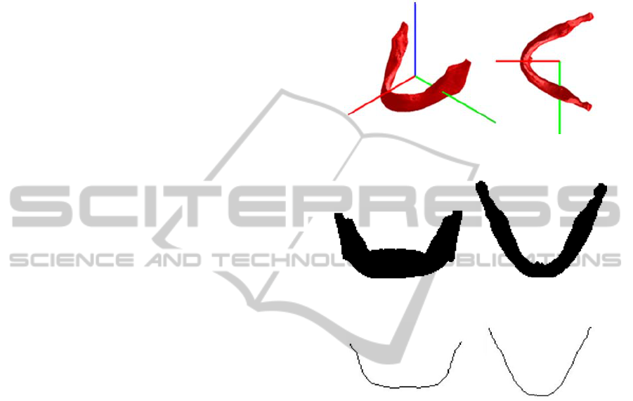
2.2 Two-dimensional Medial-axis
The vertexes of the mandible STL model are
extracted as 3D points which are then encoded into
2D images by projecting the points onto its principle
planes, the y-z plane (front view) and the x-y plane
(top view) with a proper scale factor, as shown
in
Fig. 2. Image processing technique is applied to find
the medial-axis in each image. The two 2D medial
axes can be obtained by a simple contour thinning
process. The medial-axes retain the profile and
shape of the mandible in the two principle planes
(Fig. 3).
Figure 1: Result of the best plane searching.
Figure 2: Mandible images. (L) Front view (R) Top view.
Figure 3: Medial-axis. (L) Front view (R) Top view.
2.3 Reference Line
Because a medial-axis contains two-dimensional
information, two medial axes in orthogonal view
preserve the 3D coordinates of the medial-axis.
Therefore, a 3D curve that passes through the points
of medial-axis can be constructed according to a
corresponding coordinate of both medial-axes. Fig. 4
shows such a 3D curve; it is a primary reference
line. Obviously, the primary reference line is very
rough and discontinuous caused by the image
resolution and digitization. In order to make a
smooth reference line, we reconstruct the 3D curve
by fitting it a B-spline function so that it is smooth
anywhere, as shown in Fig. 5.
MANDIBLE PARAMETERIZATION USING A REFERENCE LINE
549
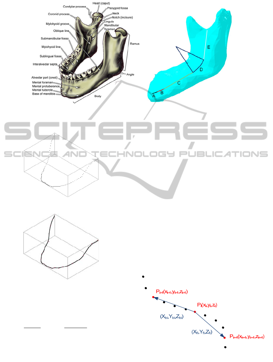
Figure 6: (Left) Mandible anatomy, (Right) Reference line segmentation. The left figure is from http://withealth.net/en/
facial-bone-anatomy.
Figure 4: A primary reference line.
Figure 5: Reference line (B-spline).
A B-spline curve of p
th
order is defined as:
() ()
,
0
01
n
ip i
i
Cu N uP u
=
=≤≤
∑
(1)
() () ()
()
1
,,1 1,1
11
1
,0
1
0
ip
i
ip ip i p
ip i ip i
ii
i
uu
uu
Nu N u N u
uu u u
uuu
Nu
otherwise
++
−+−
++++
+
−
−
=+
−−
≤<
⎧
=
⎨
⎩
(2)
Where P
i
are control points, and N
i,p
(u) is the basic
function of the B-Spline. The further derivation is
described in (Tsai, 2011).
3 PARAMETERIZATION
According to the anatomical feature of the mandible,
the reference line can be simplified into arc and
straight-line portions for the left and right halves
(Fig. 7). We search for the bending portions of the
reference line using the 3D bending value that
extended from 2D (Wang, 1995), the 3D bending
value is defined by the following equations:
=
+
+
+
+
+
(3)
=
−
=
−
=
−
=
−
=
−
=
−
(4)
Where k is a step length indicates the number of
point forward and backward. Fig. 7 illustrates a case
of k = 4.
Figure 7: Bending value of P
i
with k equal to 4.
According to the bending values, high and low
curvature portions of the B-Spline curve can be
BIOSIGNALS 2012 - International Conference on Bio-inspired Systems and Signal Processing
550
distinguished by an appropriate threshold. We then
generate arc segments to replace the high curvature
portions, and straight-line segments to replace the
low curvature portions of the B-Spline curve. The
boundary condition between the arc and the straight-
line segments is continuous up to the first derivative,
i.e. they have the same slope. It is interested to
discover the segments are coincident to the
“Symphysis, Body, Angle, and Ramus” defined by
the anatomy features.
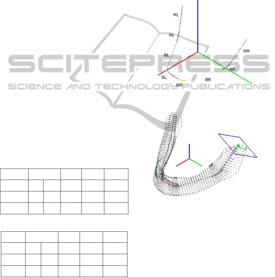
Then, non-dimensional parameters are specified
to each segment, and each segment is evenly divided
into 10 to 15 nodes according to the length. The
parameterization begins from the symmetric node,
then Symphysis, Body, Angle, and stop at Ramus.
For each left and right side, the Symphysis has ten
nodes, Body has 15 nodes, Angle has 10 nodes, and
Ramus has 15 nodes. Total of 101 nodes are
specified. Every node is given a non-dimensional
parameter (NDP). Each NDP contains two characters
and a number. The first letter is extracted from the
first character of the name of this mandible portion.
The second letter specifies the left or right half of the
section located. The last digit represents the order of
node in this segment (Fig. 8). For example, SL3
means the third node in the left side of
Symphysis
portion. Tables 1 and 2 list the left and right portions
of the NDP code, respectively. Besides, the data
structure of each node contains the position (x, y, z)
of the node on the reference line of the mandible and
the normal vector (I
x
, I
y
, I
z
) of the sectional plane
that passing through the node.
Table 1: The NDP codes (left half).
Mandible
portion
Left
Symphysis
Left
Body
Left
Angle
Left
Ramus
Line
segment
A B C D E
Number of
nodes
5+(1) 5 15 10 15
NDP SL0-5
SL6-
10
BL1-15 AL1-10 RL1-15
Table 2: The NDP codes (right half).
Mandible
portion
Right
Symphysis
Right
Body
Right
Angle
Right
Ramus
Line
segment
A B C D E
Number of
nodes
5+(1) 5 15 10 15
NDP SR0-5
SR6-
10
BR1-15 AR1-10 RR1-15
3.1 Sectional Contour of Mandible
The nodes on the reference line preserve the profile
of mandible but they alone cannot re-generate the
whole 3D mandible shape. Sectional contour at each
node is also required for reconstructing the mandible
model. In order to reduce the number of the data
point, we just recode the intersection points between
the original mandible triangular mesh and the 101
sectional planes. The normal vector of each plane is
defined by the direction of the straight-line segments
or the tangent of the arc portions. The resultant 101
sectional contours are shown in Fig. 9.
Figure 8: 101 nodes with codes.
Figure 9: 101 sectional contours of the mandible.
3.2 Structure Points
However, the number of contour point in a section is
not the same due to the original meshes of the
mandible STL models are not generated in the same
density. A normalized method is to re-sample the
contour points with equal spanning angle from the
node to the perimeter. The re-sampled contour points
are called the structure points to preserve the
mandible cross-sectional structure. For the contour
points in each section, the top and bottom crest
points are found first. Then 40 structure points are
re-sampled from the contour points; twenty are
located in the buccal side, and another twenty are in
MANDIBLE PARAMETERIZATION USING A REFERENCE LINE
551

the lingua side. Fig. 10 illustrates the definition of
the structure points. The lowest point is set as the
first point (P
0
), and the top crest point is set as the
twentieth (P
20
); the rest of points are generated by
interpolation. Based on the definition, the second to
the nineteenth point are located on the lingua (inner)
side of the mandible, and the twenty-first to the
thirty-ninth points are located on the buccal (outer)
side.
Figure 10: Definition of structure points of a section.
4 RESULT AND APPLICATION
The two mandible STL files in this paper were
provided by E-DA hospital (Kaohsiung, Taiwan); it
originally contains 44062 and 138564 polygons with
21981 and 68962 vertices, respectively. After
parameterization, they all reduced to a standardized
4400 structure points. Triangular meshes can be
easily built to reconstruct the mandible STL models.
4.1 Comparison
To evaluate the accuracy of reconstructed mandible
model, the differences between the original mandible
STL and the newly re-built one were measured.
Figure 11 shows a view that the two models are
overlapped. The maximum discrepancy between the
two models is measured about 0.2 mm, which is
precise enough for surgical planning and locating the
cutting area for reconstruction purpose. More cases
are going to be re-built to verify the algorithm by
checking the geometrical integrity and the accuracy
of the new mandible models.
Figure 11: Comparison of the original model (in red), and
the reconstructed one (in blue).
4.2 Mandible Reconstruction
Parameters
For the application of mandible parameterization, we
have also developed a user interface to cut the
mandible three-dimensionally according to the NDP.
Users can move a cutting plane along the reference
line, and rotate the plane about two axes defined by
the local coordinate of the line to range the defected
portion. There are three reconstruction parameters
for recording a cutting plane, which are the NDP
code of the section on the reference line, and two
rotation angles
α
and
β
. The rotation angles are,
respectively, about the normal and bi-normal vectors
of the local coordinate system along the reference
line. Fig. 12 illustrates a cutting process using NDP
as a guide. Of course, a real cutting guider can be
molded according to the NDP code using rapid-
prototyping technology.
To plan for the fibula cut, parameterization of
fibula based on the same strategy is also necessary. It
is easy to do so since the fibula is simply a
cylindrical shape. Once the orientation of fibula flap
is determined, then align the fibula cross section
with that of mandible can be done by using the NDP
code. The surgical planning can be accomplished in
computer by “placing” the fibula STL model onto
the mandible reference line and cutting the fibula
into segments. The length of fibula segment can be
determined by setting a tolerance between the
bended contour of the reference line and the
corresponding straight-line contour of the fibula.
Moreover, the fibula flap can be placed in a desired
orientation on the mandible since the number of
structure point indicates the top, lingua, bottom, and
buccal side. In all, this study established an
infrastructure for the computer assisted mandible
reconstruction using fibula flap. Without a standard
P
0
P
20
P
1
~P
19
P
21
~P
39
BIOSIGNALS 2012 - International Conference on Bio-inspired Systems and Signal Processing
552

parameterization, there would be no information for
the removal locations of the mandible, and fibula
bone would have no reference to align with the
mandible for cutting into segments.
Figure 12: Process of cutting a mandible. (a) Select cutting
position. (b) Rotateαdegree about x-axis. (c) Rotateβ
degree about y-axis. (d) Set up the first cutting plane. (e)
Result of the first cut. (f) Result of the second cut.
5 CONCLUSIONS
This paper postulates an idea and provides an
approach of mandible parameterization using a
reference line. The reference line represents the
profile of mandible. The reference line is divided
into four portions that represent the Symphysis,
Body, Angle, and Ramus. The new standardized
mandible model has 101 nodes that register as the
NDP code. Each section passing through the node
contains 40 contour points. These sectional structure
points can faithfully regenerate the true shape of
mandible. After parameterization, the removal nidus
portion of the mandible is indicated by the NDP
code and the defected portion can be reconstructed
by using the parameters as a guide. Besides, the
order of structure point also indicates the orientation
of the mandible cross-sectional direction, especially
the lingua and buccal sides, which facilitates the
placement of the fibula flap on the right orientation
of the mandible. The parameterization makes the
mandible reconstruction by numerical computation
possible. It is essential for surgical planning in a
CAD system, which is our future work to be done.
REFERENCES
Cohen, A., Lavev, A., Berman, P., Nashef, R., Abu-Tair, J.,
2009, “Mandibular Reconstruction Using Stereolitho-
graphic 3-dimensional Printing Modeling Technology”
Vol. 108, Journal of Oral and Maxillofacial Surgery.
Hallermann, W., Olsen, S., Bardyn, T., Taqhizadeh, F.,
Banic, A., lizuka, T., 2006, “A New Method for
Computer-Aided Operation Planning for Extensive
Mandibular Reconstruction”, Vol. 117, Plastic and
Reconstructive Surgery.
Ferri J., Piot B., Ruhin B., Mercier J., 1997, “Advantages
and Limitations of the Fibula Free Flap in Mandibular
Reconstruction”. Vol. 55, Journal of Oral and
Maxillofacial Surgery.
Strackee, S. D., Kroon, F. H., Spierings, P. T., Jaspers, J.
E., 2004, “Development of A Modelling and
Osteotomy Jig System for Reconstruction of the
Mandible with A Free Vascularized Fibula Flap”, Vol.
114, Plastic and Reconstructive Surgery.
Tsai M. J., Lee, H. W. Ann, N. J., 2011, “Machine Vision
Based Path Planning for a Robotic Golf Club Head
Welding System,” Robotics and Computer-Integrated
Manufacturing, 27, 2011, pp. 843-849.
Wang, M. J., Wu, W. Y., Huang, L. K., Wang, D. M.,
1995, “Corner detection using bending value”, Vol. 16,
Pattern Recognition Letters.
Wang, T. H., Tseng, C. S., Hsieh, C. Y., Ma, H., Shen, B.
H., Perng, C. K., Tiu, C. M., 2009, “Using Computer-
Aided Design Paper Model for Mandibular
Reconstruction: A Preliminary Report”, Vol. 67,
Journal of Oal and Maxillofacial Surgery.
Yeung, R. W., Samman, N., Cheung, L. K., Zhang, C.
Chow, R. L., 2007, “Stereomodel-Assisted Fibula Flap
Harvest and Mandibular Reconstruction”, Vol. 65,
Journal of Oral and Maxillofacial Surgery.
Yoo, D. J., 2011, “Three-dimensional Surface
Reconstruction of Human Bone Using A B-spline
Based Interpolation Approach”, Vol. 43, Computer-
Aided Design.
Zachow, S., Lamecker, H., Elsholtz, B., Stiller, M., 2005,
“Reconstruction of Mandibular Dysplasia Using A
Statistical 3D Shape Model”, Vol. 1281, International
Congress Series.
MANDIBLE PARAMETERIZATION USING A REFERENCE LINE
553
