THE INFLUENCE OF TEXTURED SURFACES ON
THE LUBRICATION OF ARTIFICIAL JOINT PROSTHESES
Eduardo de la Guerra Ochoa, David del Sordo Carrancio, Javier Echávarri Otero,
Enrique Chacón Tanarro, Andrés Díaz Lantada and Pilar Lafont Morgado
Grupo de Investigación en Ingeniería de Máquinas-E.T.S.I. Industriales, Universidad Politécnica de Madrid,
c/ José Gutiérrez Abascal 2, 28006, Madrid, Spain
Keywords: Tribology, Textured Surface, Artificial Prosthesis, Photolithography, Chemical Etching.
Abstract: The development of artificial joint prostheses is an especially relevant advance linked to the combined use
of medical and engineering sciences. In ideal conditions a joint prosthesis should last the whole patient’s
life. For a younger patient, that is normally linked to using enhanced designs capable of reducing friction
and wear rate, thus increasing patient’s comfort and prosthesis service life. Present study concentrates on
validating the use of micro-textured surfaces for improving friction and minimizing wear rate by means of
increasing the (elasto) hydrodynamic lubrication range. Micro-textured surfaces have been obtained by UV-
photolithography upon photosensible films and subsequent chemical etching of the uncoated surface zones.
A ball-plane contact tribometer has been used to assess the friction coefficient of the different micro-
textured surfaces in order to validate our approach. Significant reductions of friction coefficient have been
obtained thanks to the micro-textures, what provides useful information for computer-aided design &
manufacturing processes linked to the development of innovative and efficient biomimetic prostheses.
1 INTRODUCTION
Synovial joints allow the relative movement
between bones of the human body. They operate in a
similar way as bearings, reducing friction and wear
in the contact. Typical examples of such joints are
that of the hip, knees, shoulders and phalanges of the
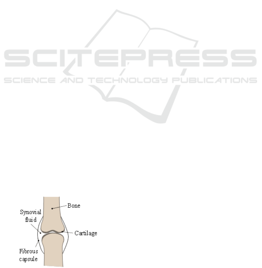
fingers. Figure 1 shows a schematic illustration
(Bergmann, 2010).
Figure 1: Outline of a synovial joint.
As shown in Figure 1, the two bones, with
relative movement, are separated by a cartilage and a
synovial fluid that lubricates the contact. In order to
avoid the loss of lubricant, a fibrous capsule covers
the joint. By means of this configuration, friction
coefficients attained in the joints vary from 0.005 to
0.025, depending on the age and physical conditions
of the patient (Gohar, 2008).
As time goes by, likewise in case of lesion or
disease, joints can present inflammations or wear,
i.e. arthritis. Therefore, characteristic consequences
may arise: movement constraint, joint swelling,
trembling, pain, progressive strength loss and
deformity of the body part affected (Dumbleton,
1981). These symptoms can become very annoying
and dramatically reduce life-quality of the sufferer.
When neither rehabilitation nor medication can
mitigate the arthritis symptoms, damaged joint is
generally replaced by an artificial prosthesis. Most
artificial joint prostheses present two main parts,
each of them placed in one of the two bones of the
joint.
Relative movement is allowed between them,
sometimes including an additional intermediate part
for improving contact phenomena. The types of
contacting materials used for prostheses are very
diverse: ceramic, polymeric, metallic and their
291
Ochoa E., Del Sordo Carrancio D., Echávarri Otero J., Chacón Tanarro E., Díaz Lantada A. and Lafont Morgado P..
THE INFLUENCE OF TEXTURED SURFACES ON THE LUBRICATION OF ARTIFICIAL JOINT PROSTHESES.
DOI: 10.5220/0003908902910294
In Proceedings of the International Conference on Biomedical Electronics and Devices (BIODEVICES-2012), pages 291-294
ISBN: 978-989-8425-91-1
Copyright
c
2012 SCITEPRESS (Science and Technology Publications, Lda.)
combinations (Pinchuk, 2006). The most usual
selection is a quasi-spherical metallic element
(stainless steel, Co-Cr-Mo, Co-Ni-Cr-Mo or Ti
alloys, in many cases with ceramic coatings) housed
in a plastic element (mainly ultra-high-molecular-
weight polyethylene or UHMWPE). Prostheses must
operate under very variable conditions (from static
conditions to very high sliding velocities) and in
such a delicate environment like the human body.
Therefore, good friction behavior and wear
resistance are required with the aim of avoiding the
need to substitute them, i.e. life of the prostheses is
expected to be longer than that of the patient.
2 LUBRICATION IN
PROSTHESES AND JOINTS
In mechanical systems three main lubrication
regimes are distinguished: boundary, mixed and
elasto(hydrodynamic)-EHL. The friction coefficient
and wear under each regime are very different, as
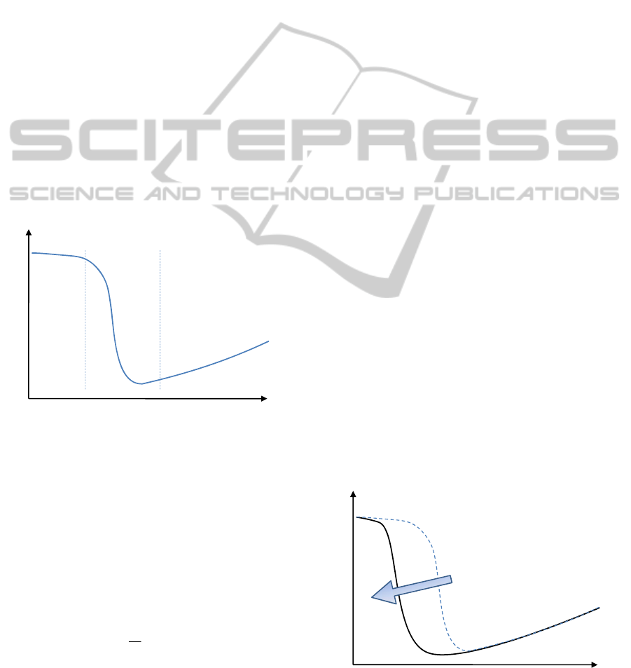
shown in Stribeck’s curve (Figure 2).
Figure 2: Different lubrication regimes in Stribeck’s curve.
The differences among regimes are given by the
specific film-thickness parameter (λ), which
provides the relation between the lubricant film-
thickness (h) and the combined roughness of both
surfaces (σ), see Eq. 1. When λ>3 a complete
separation between surfaces is attained and therefore
EHL regime prevails. When 1<λ<3 the separation is
partial and mixed lubrication is assumed. Finally,
when λ<1, the contact works under boundary
lubrication regime (Stachowiak, 2005).
σ
λ
h
=
(1)
In most working conditions, joints operate under
mixed lubrication, where the separation between
contacting surfaces is incomplete. Thus, low friction
coefficients are obtained due to the composition of
synovial fluid: including a liberation and
accumulation of glycoproteins and hyaluronic acid
within the cartilage interstices when the joint is
submitted to pressure (Gohar, 2008).
In the case of artificial joint prostheses, the
accumulation of synovial fluid is much more
complex, as they are manufactured with very low
surface roughness (10 – 50 nm), what stands for a
specular finish on both contact surfaces. Such
extremely low roughness promotes a positive increase
of lubricant film thickness for low sliding velocities.
However a polished surface cannot effectively
retain lubricant and important adhesion and wear
problems appear at rest or at the beginning of
movement, as the contact is almost dry in such
conditions.
3 SURFACE
MICRO-TEXTURIZATION
3.1 Expected Benefits
of Micro-texturization
The main objective for introducing micro-textures
on the contact surfaces of artificial joint prostheses
is to fulfill the need of retaining synovial fluid at
very low velocities. At the same time low surface
roughness is maintained, what allows for a complete
lubrication regime in such conditions.
Hence a lower friction coefficient is expected for
the whole functioning range and wear rate of
prostheses can be minimized and debris particle
formation can also be importantly reduced
(Kennedy, 2000). In addition the presence of micro-
textures somehow imitates nature and promotes
tissue formation and biointegration of the prostheses
(Díaz Lantada, 2010).
Figure 3: Improvement in Stribeck curve thanks to the use
of micro-textured surfaces.
Coefficient of friction, μ
λ=h/σ
EHL
Mixed
Boundary
High
wear rate
Contact
between
surfaces
Very-low wear rate
Complete separation
between surfaces
Low wear rate
Partially separation
between surfaces
μ
λ
=
h/σ
EHL
Mixed
Boundary
Textured surface enlarge the EHL zone
reducing friction and wear
BIODEVICES 2012 - International Conference on Biomedical Electronics and Devices
292
The expected effects upon Stribeck curve (as
shown in Figure 2) are schematically described in
Figure 3, showing a beneficial reduction of friction
thanks to the presence of micro-textures (Petterson,
2003, Wakuda, 2003).
3.2 Micro-texture Design
Computer-aided design (CAD) tools have been used
for the design of micro-texturization patterns, so that
the characteristics of the textures could be controlled
and modified in an easy way. A texturization pattern
based on the repetition of circular features, with
diameter (φ) and surface density (d) as main control
parameters (see Eq. 2), has been used for our
validation..
2
2
(%) ·100
4
d
l
πφ
=
(2)
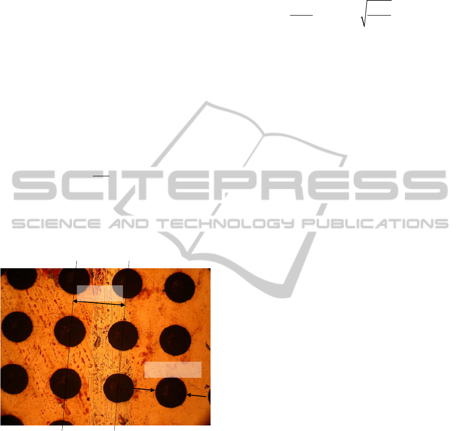
Figure 4 provides an example of one of the
micro-textured surfaces obtained by following the
manufacture process explained further on. Main
parameters are also included (in this case φ = 400
μm and l = 1.12 mm).
Figure 4: Final textured surface.
Feature diameter was selected using as reference
the hertzian contact radius (a), Eq. 3, for a ball-plane
contact (Echavarri, 2011), as a ball-plane contact
tribometer was applied for analyzing the influence of
micro-texturization on friction coefficient (see trials
and results section).
The contact radius depends on the load (W), on
the equivalent contact radius (R*) and on the
reduced Young modulus (E´). In this study three
different diameters have been used, one below, one
similar and one above estimated contact diameter:
100, 200 and 400 μm. Surface densities of 10% and
25% have been studied in combination with the
aforementioned radii.
*
3
0
2
33
2'2
WWR
pa
Ea
π
==
(3)
3.3 Micro-texture Manufacture
In this work we have used copper discs as substrate
material for studying the effect of micro-
texturization on friction coefficient. Micro rapid
prototyping technologies, in this case a combination
of UV photolithography and chemical etching, have
allowed us to obtain the micro-textures. In this
preliminary validation we have used copper as
substrate material due to its easier processability and
the need of a lower etching time.
For the manufacture of the micro-textures we
have followed several steps including:
Initial preparation of the copper discs by
washing out the possible surface oxides in
ultrasonic cube for around 30 minutes and
subsequent drying.
Coating of the discs using Dupont Riston PM-
100 photoresin.
Exposure of the photoresin to UV light by
means of a SF-100 equipment from Intelligent
Micro Patterning LLC. The process is known
as mask-less photolithography, as the use of
programmable light filters prevents from using
a physical mask.
Development, using a Na
2
CO
3
0.85% w.
solution, for eliminating the uncured
photoresin in those pattern zones that are
going to be chemically etched
Chemical etching introducing the disc in a
FeCl
3
40% w. solution for attacking the
uncoated pattern zones, hence obtaining the
micro-texture.
Stripping or elimination of the remaining
photoresisn.
Washing out debris and drying.
Final dimensional verification.
Final result of the manufacturing process is
included in Figure 4, in which 400 μm has been used
as diameter of the circular features and a surface
density of 10% has been applied. The geometry of
the micro-holes obtained is almost semi-spherical
and, as results explained below show, they act as
reservoirs of lubricant and promote friction
reduction.
1.12mm
Φ=400μm
THE INFLUENCE OF TEXTURED SURFACES ON THE LUBRICATION OF ARTIFICIAL JOINT PROSTHESES
293
4 TRIALS AND RESULTS
Once the textures of the different probes were
obtained, several trials have been carried out in a
Mini Traction Machine from PCS Instruments
(Lafont, 2009), simulating a ball-disc contact, using
a steel ball and the micro-texturized copper discs.
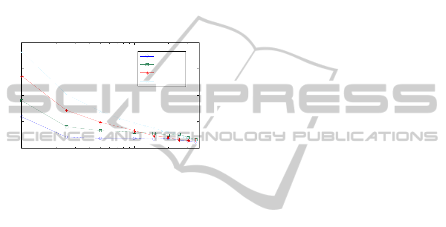
Figure 5 shows the evolution of friction
coefficient as a function of mean velocity (u
m
), for
different diameters of the circular features of the
micro-textured patterns. A smooth disc without
micro-texturization has been used as reference.
Figure 5: Friction reduction by using textured surfaces.
The friction coefficient reduction is specially
noteworthty in the mixed lubrication regime
(u
m
<10
3
mm/s). In addition smaller textures promote
greater reductions of friction, specially for lower
contact velocities.
5 CONCLUSIONS
AND APPLICATIONS
Our results show that the use of very simple micro-
textures helps to improve surface contact behavior
and reduce friction coefficient in the whole mixed
lubrication regime, although additional in vivo
validation needs to be further researched.
Applying this methodology to the contact
surfaces of artificial joint prostheses can help to
obtain low surface roughnesses with micro-textures
acting as reservoirs of lubricant, thus minimizing
friction and improving wear behavior and prostheses
service life. Such textures have also potential
benefits regarding cell growth and tissue formation
besides the prostheses. Future studies will be linked
to the use of end materials and geometries adapted to
those of the different artificial joint prostheses
designs. Industrialization of the proposed process
can be achieved by means of CAD-CAM
technologies, in combination with advanced additive
manufacturing or laser micro-mechanization.
REFERENCES
Bergmann, T. F., Peterson, D. H., (2010). Chiropractic
Technique, Principles and Procedures, Elsevier, 3
rd
edition
Díaz Lantada, A., Lafont Morgado, P., et al. (2010).
Substrato cuasibidimensional para crecimiento de
células y tejidos y método de obtención del mismo.
Spanish Patent and Trademark Office, Patent
application number P201030957.
Dumbleton, J. H., 1981. Tribology of natural and artificial
joints, Tribology Series, 3, Elsevier, London.
Echávarri, J., Lafont, P., et al. (2011). Analytical model
for predicting the friction coefficient in point contacts
with thermal elastohydrodynamic lubrication. Proc.
IMechE, Vol. 225 Part J: J. Engineering Tribology. pp.
181-191.
Gohar, R., Rahnejat, H. (2008). Fundamentals of
Tribology, Imperial College Press, London 1
st
edition.
Kennedy, F.E. et al., (2000), Contact fatigue failure of
ultra-high molecular weight polyethylene bearing
components of knee prostheses. Journal of Tribology,
Vol. 122, pp. 332-339.
Lafont, P., Echávarri, J. et al. (2009). Models for
predicting friction coefficient and parameters with
influence in elastohydrodynamic lubrication. Proc.
IMechE, Vol. 223 Part J: J. Engineering Tribology. pp.
947-958.
Petterson, U., Jacobson, S., (2003). Influence of surface
texture on boundary lubricated sliding contacts”.
Tribology International, 36, pp. 857-864.
Pinchuk, L. S., Nikolaev, V. I., Tsvetkova, E. A., Goldade,
V. A., (2006). Tribology and biophysics of artificial
Joints, Elsevier, London 1
st
edition.
Stachowiak, G. W., Batchelor, A. W., (2005). Engineering
tribology, Butterworth-Heinemann.
Wakuda, M., Yamauchi, Y., Kanzaki, S., Yasuda, Y.,
(2003). Effect of surface texturing on friction
reduction between ceramic and steel materials under
lubricated sliding contact. Wear, 254, pp. 356-363.
10
2
10
3
0.02
0.025
0.03
0.035
0.04
u
m
(mm/s)
µ
Effect of textured diameter. W=20N
R=50
μ
m
R=100
μ
m
R=200
μ
m
Smooth
BIODEVICES 2012 - International Conference on Biomedical Electronics and Devices
294
