
VELOCITY VECTOR FIELD VISUALIZATION OF FLOW IN
LIQUID ACQUISITION DEVICE CHANNEL
John B. McQuillen
1
, David F. Chao
1
, Nancy R. Hall
1
and Nengli Zhang
2 †
1
NASA Glenn Research Center, Cleveland, OH 44135, U.S.A.
2
Ohio Aerospace Institute at NASA Glenn Research Center, Cleveland, OH 44135, U.S.A.
Keywords: Velocity Vector, Liquid Acquisition Device (LAD), Flow Pattern, CFD Simulation, Vertically Submerged
Screen Channel, Gravity Effects.
Abstract: A capillary flow liquid acquisition device (LAD) for cryogenic propellants has been developed and tested in
NASA Glenn Research Center to meet the requirements of transferring cryogenic liquid propellants from
storage tanks to an engine in reduced gravity environments. The prototypical mesh screen channel LAD was
fabricated with a mesh screen, covering a rectangular flow channel with a cylindrical outlet tube, and was
tested with liquid oxygen (LOX). In order to better understand the performance in various gravity
environments and orientations at different liquid submersion depths of the screen channel LAD, a series of
computational fluid dynamics (CFD) simulations of LOX flow through the LAD screen channel was
undertaken. The resulting velocity vector field visualization for the flow in the channel has been used to
reveal the gravity effects on the flow in the screen channel.
1 INTRODUCTION
As is well known for a space mission, liquid
propellants have to be delivered from their storage
tanks to an engine in a liquid state. It is easy to
realize the delivery on earth using gravity to position
liquid above the tank outlet that is located at the tank
bottom. However, it is impossible to ensure the
propellant drainage from the tank without vapor or
pressurant gas entrainment in the low gravity
environment of space, because of the uncertainty in
the ullage position. One type of propellant
management device, a liquid acquisition device
(LAD), uses capillary flow and surface tension to
acquire liquid has been developed and well
characterized for storable (noncryogenic)
propellants. Many of LADs have been built, tested
and used for hypergolic propellants, such as nitrogen
tetroxide (N
2
O
4
) and monomethyl hydrazine
(MMH), but the development for use with cryogenic
propellants has been lagging. LADs are custom
designed to fulfill a unique set of requirements under
the appropriate environmental mission conditions
and demands; consequently, there is no universal
design that satisfies all applications (Fester et al,
1976). Future space vehicles will require the use of
non-toxic, cryogenic propellants, because of the
performance advantages over the toxic hypergolic
propellants and also because of the environmental
and handling concerns (Kudlac and Jurns, 2006).
Capillary-flow LADs have been well characterized
for storable toxic propellants (Chato and M.T.
Kudlac, 2002; Kudlac and Jurns, 2006), but there
have been only a few LAD experiments with
cryogenic propellants, including liquid oxygen
(LOX). Recently, Zhang et al (2009) performed a
CFD simulation for sub-cooled LOX flow in LAD
channel test assembly in normal gravity
environment. McQuillen et al (2012) conducted a
series of CFD simulations of the LOX flows in LAD
channel in different gravity environments for various
flow rates. All of these simulations are for a
“horizontally” submerged LAD channel in the LOX.
This paper reports the CFD simulation results for
“vertically” submerged in the LOX at normal gravity
environment, revealing the gravity effects on the
flow in the screen channel through velocity vector
field visualizations produced by the simulation.
†
Corresponding author, Tel: 216-433-8750, Fax: 216-
433-8050
743
B. McQuillen J., F. Chao D., R. Hall N. and Zhang N..
VELOCITY VECTOR FIELD VISUALIZATION OF FLOW IN LIQUID ACQUISITION DEVICE CHANNEL.
DOI: 10.5220/0003909807430748
In Proceedings of the International Conference on Computer Graphics Theory and Applications (IVAPP-2012), pages 743-748
ISBN: 978-989-8565-02-0
Copyright
c
2012 SCITEPRESS (Science and Technology Publications, Lda.)
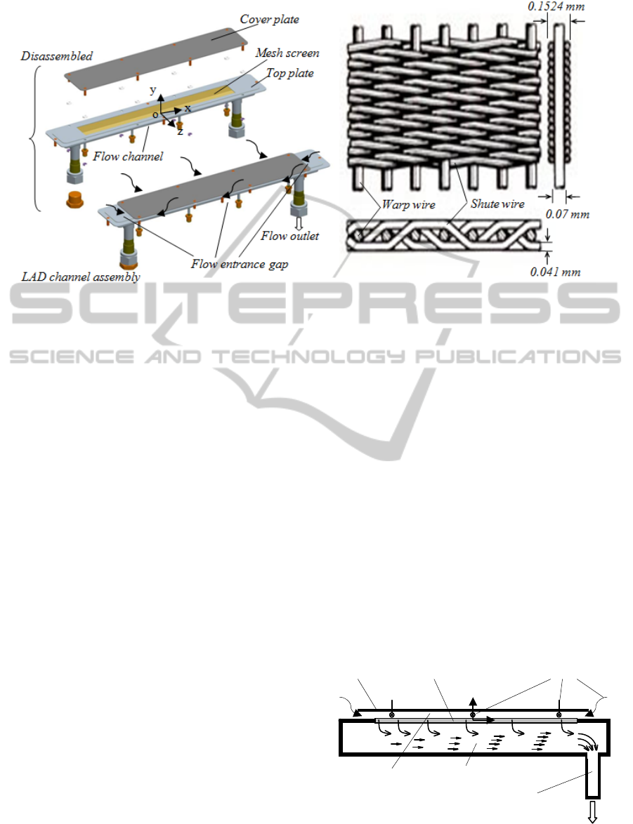
Figure 1: Prototypical LAD screen channel assembly and Geometry of Dutch Twill mesh.
2 LAD CHANNEL ASSEMBLY
Under NASA’s continuing Cryogenic Fluid
Management (CFM) development program, a
prototypical LAD screen channel assembly was
designed and tested using LOX in NASA Glenn
Research Center, as shown in Figure 1 left. The
LOX flows into the channel assembly via the gap
between the cover plate and the mesh screen, so
called entrance gap, from all directions, and then
passes through the fine mesh screen to flow down of
the channel assembly and then goes out. The mesh
screen consists of stainless steel wires arranged in a
200x1400 Dutch Twill weave mesh. This geometry
is shown in Figure 1 right. The LOX flow path is
shown schematically in Figure 2. Since most liquids,
including LOX, perfectly wet stainless steel
surfaces, the liquid wets the entire screen when the
screen partially contacts the liquid pool, thus
effectively blocking gas passage through the porous
screen unless a critical pressure differential across
the screen, is exceeded. This pressure differential is
called the bubble point. The procedure for bubble-
point test is described in American Society for
Testing and Materials Standard (ASTM) Method
F316
.
3 CFD SIMULATION SETTINGS
Since the Dutch Twill mesh screen is very thin
compared to the LAD channel dimensions, the
screen is approximated to a porous sheet and is
handled as porous-jump in the CFD simulations of
the LAD channel flow using FLUENT. Two primary
parameters, the face permeability,
α,
and the
pressure jump coefficient, C
2
, define the porous-
jump in FLUENT, which can be determined
experimentally. The relevant reviews and calculation
methods have been given by Zhang et al. (2009) and
McQuillen et al. (2012).
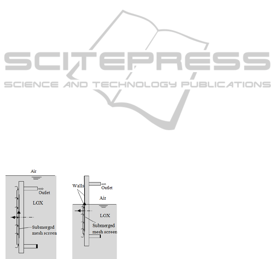
In order to simulate the cases of vertically partial
submersions of the LAD channel in LOX, several
geometry models have been established, including
full submersion and partial submersion depths of the
mesh screen, such as 1/3, 1/2, and 2/3 of the screen
length submerged. For the partially submerged cases,
the exposed portion of the mesh screen was taken as
a solid wall, as shown in Figure 3. This is reasonable
because no liquid or vapor can flow through this
portion of the screen provided that the local pressure
Figure 2: Fluid flow route in the LAD channel assembly.
Cover plate
Flow entrance
Outlet-tube
L
AD
f
low channel
Flow outlet
Fine mesh Screen
Entrance channel
y
x
IVAPP 2012 - International Conference on Information Visualization Theory and Applications
744
drop between the vapor and the LOX does not
exceed the bubble point.
The pressure-based solver was used, with a
steady implicit formulation. The three-dimensional
simulations used the Green-Gauss cell based
gradient and the standard k-epsilon model for the
turbulent flow with the following constants: The
coefficient of first order turbulent dissipation rate in
the dissipation rate equation, C
1
ε
= 1.44; the
coefficient of second order turbulent dissipation rate
in the dissipation rate equation C
2
ε
= 1.92; the
turbulent viscosity coefficient C
μ
= 0.09; the
turbulent Prandtl number for turbulent kinetic
energy,
σ
k
= 1.0; and the turbulent Prandtl number
for dissipation rate of turbulent kinetic energy,
σ
ε
=
1.3.
The operating conditions were set to a system
pressure = 1620269 Pa, T= 89 K, and gravitational
acceleration vectors were set at g
x
= g
z
= 0.0 m/s
2
,
and g
y
= -9.81 m/s
2
for the horizontally-oriented
completely submersion cases, while g
y
= g
z
= 0.0
m/s
2
, and g
x
= -9.81 m/s
2
for vertically-oriented
completely and partially submerged cases.
The ‘pressure-outlet’ type was selected as the
boundary condition at the flow outlet, and set to a
gauge pressure of 0 Pa with a backflow modified
turbulent viscosity of 0.001 m
2
/s. The ‘pressure-inlet’
type boundary condition was selected at the flow
inlet surface with corresponding values of total
gauge pressure and modified turbulent viscosity of
0.001 m
2
/s to obtain a mass flow rates within the
range of 0.0455 kg/s (0.1 lbs/s) ~ 0.1818 kg/s (0.4
lbs/s). It
should be noted that all the gauge pressures
are relative to the operating pressure.
Figure 3: Vertically submerged LAD channel assembly.
4 SIMULATION RESULTS
Twenty four cases of vertically-oriented submerged
LAD channel, including six complete submerged,
seven 2/3 submerged screen length, five 1/2
submerged screen length, and six 1/3 submerged
screen length cases, were simulated. Two cases of
horizontally-oriented submerged LAD channel were
simulated for comparison with the corresponding
vertically-oriented completely submerged cases. The
simulation results show that for the completely
submerged cases, the mass flow rate passing through
the LAD channel is not affected by the orientation of
the channel. In fact, the total static pressure drop
between the inlets and outlet,
Δ
p
i-o
, and submerged
portion of the screen determines the flow rate. For
example, at the cases of completely submerged
channel, the value of
Δ
p
i-o
is proportional to the
mass flow rate and independent of channel
orientation However, as more of the screen becomes
exposed in the vertically-oriented submerged cases,
a larger
Δ
p
i-o
is needed to achieve the same mass
flow rate. As is well known, the flow pattern in the
channel directly reflects the effects of gravity on the
channel performance. In order to ascertain the
effects of the channel orientation or gravity on the
LAD channel performance, the velocity vector fields
are visualized and compared to reveal the flow
pattern characteristics.
4.1 Velocity Vector Field Visualization
For the case of vertically-oriented, completely
submerged channel, the hydrostatic pressures in both
entrance gap and LAD flow channel are the same;
therefore, gravity has no effect on the flow in the
channel. The flow pattern in the channel is no
different between the completely submerged cases
horizontally and vertically oriented channels. For
example, the velocity vectors near the outlet tube for
both cases are almost identical, as shown in Figure 4.
The velocity vectors for completely submerged
channels along the channel length at the sections of
axial distance of x = -0.16 m, x = 0 m, and x = 0.16
m, are also identical for horizontally and vertically
oriented channels, respectively, as shown in Figures
5a, 45b, and 5c, in which the left ones are for
horizontal orientation while the right ones for
vertical orientation. However, gravity affects the
flow pattern in the flow channel when a portion of
the screen is exposed. At the same
Δ
p
i-o
, the amount
of exposed screen length is proportional to the
hydrostatic pressure drop between the entrance gap
and the LAD flow channel; consequently, when the
screen exposed portion increases, the resistance of
the flow passing through the flow channel becomes
larger. As a result, the flow in the flow channel by
VELOCITY VECTOR FIELD VISUALIZATION OF FLOW IN LIQUID ACQUISITION DEVICE CHANNEL
745
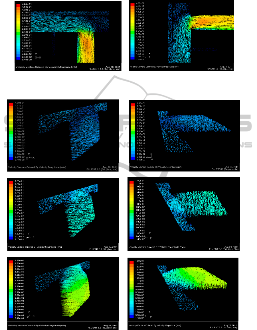
a) b)
Figure 4: Velocity vectors in the completely submerged channel near the outlet tube: a) horizontally oriented; b) vertically
oriented channel.
a) At section of x = -0.16 m.
b) At section of x = 0.0 m.
c) At section of x = 0.16 m.
Figure 5: Velocity vectors at different sections.
IVAPP 2012 - International Conference on Information Visualization Theory and Applications
746
a) In case of vertically full submersion b) In case of vertically half screen submersion
Figure 6: Velocity vectors in the channel near the outlet tube for cases of vertically submerged.
In case of vertically full submersion In case of vertically half screen submersion
Figure 7: Velocity vectors in the channel at bottom end for the cases of vertically submerged.
the outlet tube is different for the cases of various
screen exposures. For the case of vertically-oriented,
completely submerged channel, the flow has higher
velocity in the channel and a vortex occurs at the
flow channel end by the outlet tube, as shown in
Figure 6a, while for the cases of vertically-oriented
exposed screen half length, the flow enters into the
outlet tube without generating a vortex, because the
higher hydrostatic pressure drop reduces the flow
velocity in the flow channel, as shown in Figure 6b.
It should also be noted that for cases of completely
submerged channel and half submerged screen
length, the
flow direction passing though the screen
is different at the bottom end of the flow channel, as
shown in Figure 7.
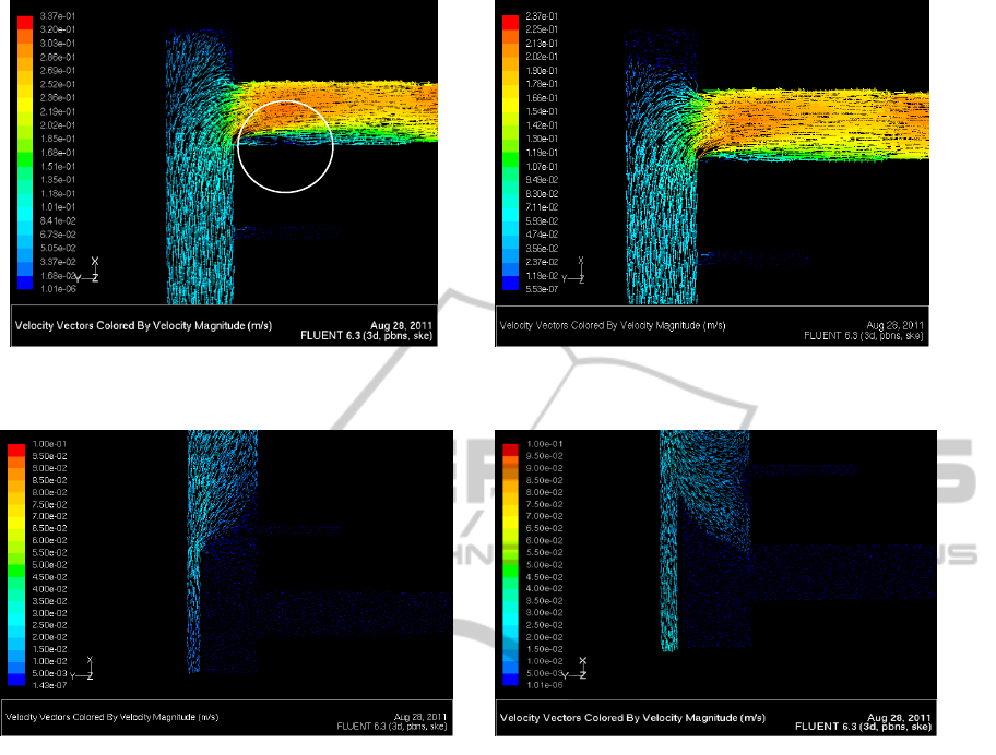
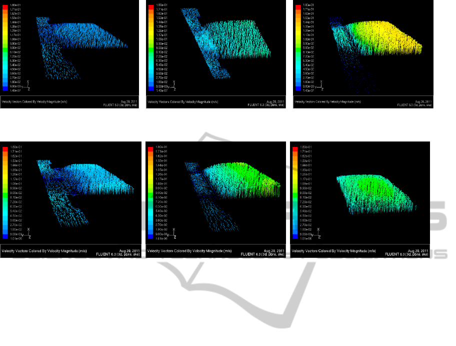
4.2 Velocity and Mass Flow Rate
Change
The CFD simulation results show that the flow
velocity and mass flow rate in the channel are
continuously augmented along the submerged
channel length (x-axis direction) when the LOX
passes through the screen and then flows toward the
outlet tube in the flow channel. The typical velocity
vectors distributions at different sections for the
cases of completely submerged and half submerged
screen length are shown in Figure 8. It is noted that
when the LOX flows in the exposed screen portion
of the channel, the flow rate maintains constant
because no LOX is added into the channel through
the screen anymore.
5 CONCLUSIONS
In virtue of the velocity vector field visualization,
the flow pattern characteristics in the capillary flow
LAD channel are revealed and the performance of
the LAD channel at different submersion cases in
normal gravity can be evaluated.
Vertex zone
VELOCITY VECTOR FIELD VISUALIZATION OF FLOW IN LIQUID ACQUISITION DEVICE CHANNEL
747
At section of x = -0.16 m At section of x = 0 m At section of x = 0.24 m
a) In case of vertically full submersion
At section of x = -0.16 m At section of x = 0 m At section of x = 0.24 m
b) In case of vertically half screen submersion.
Figure 8: Velocity vectors distributions in the channel assembly at Δp
i-o
= 400 Pa.
1. The flow patterns in the completely
submerged LAD channel are identical between the
cases of horizontal and vertically-oriented channels.
2. The gravity effects flow pattern in the flow
channel when as of the amount of exposed screen
length is varied. At the bottom end of the channel,
far away from the outlet tube, the hydrostatic
pressure drop reverses the flow direction of the LOX
passing the screen, while at the top end of the
channel, the flow smoothly enters into the outlet
tube without vortex, which is contrary to one in the
completely submerged channel.
3. The flow velocity and mass flow rate in
the channel are continuously augmented along the
channel length (x-axis direction) when the LOX
passes through the screen and then flows toward the
outlet tube in the flow channel. However, when the
LOX flows in the exposed screen portion of the
channel, the flow rate is constant.
REFERENCES
Chato, D. J. and Kudlac, M. T., 2002. In: 38
th
AIAA/ASME/SAE/ASEE Joint Propulsion Conference
& Exhibit, Indianapolis, IN, see also Paper AIAA
2002-3983.
Fester, D. A., Villars, A. J. and Uney, P.E., 1976. Journal
of Spacecraft and Rocket ,13: 522-527.
Kudlac, M. T. and Jurns, J. M., 2006. In: 42
nd
AIAA/ASME/SAE/ASEE Joint Propulsion Conference &
Exhibit, Sacramento, CA, see also Paper AIAA 2006-
5054.
McQuillen, J. B., Chato, D. J., Motil, B. J., Doherty, M.
P., Chao, D. F. and Zhang, N., 2012. Journal of
Porous Media (in print).
Zhang, N., Chato, D. J., . McQuillen, J. B., Motil, B. J.
and Chao, D. F., 2009. World Academy of Science,
Engineering and Technology, 58: 1180-1185.
IVAPP 2012 - International Conference on Information Visualization Theory and Applications
748
