
A “PARTIALLY VIRTUAL” MICROCONTROLLER
LABORATORY
Shlomo Engelberg
1
and Cecile Yehezkel
2
1
Department of Electronics, Jerusalem College of Technology, Jerusalem, Israel
2
Bar-Ilan University, Ramat-Gan, Israel
Keywords: Computer-assisted Instruction, Distance Learning, Virtual Labs, Web Lectures and Notes.
Abstract: In this paper, we describe our experiences running a “partially virtual” microcontroller lab. We show that
though the virtual portion of the lab can contribute to the students’ understanding, there are also several
pitfalls that must be avoided or dealt with. We have found that our “virtual microcontroller” simulates a true
microcontroller to a reasonable extent, but there are cases in which the simulator does not properly simulate
the microcontroller. It is critical that students be taught to think of “virtual equipment” as something distinct
from the real equipment and as something with idiosyncrasies of its own.
1 INTRODUCTION
At Bar Ilan University, we have been running a
microcontroller lab for the last eight years. The lab
is a hardware lab – the students use the evaluation
kit for the Analog Devices ADuC841 to learn how a
microcontroller is used. Both in the labs and at
home, the students are expected to use Keil uVision4
integrated development environment (IDE) to write,
simulate, and download programs to the
microcontroller. The lab manual that the students
use (Engelberg, 2012) covers the theoretical material
needed throughout most of the course and describes
the laboratory exercises that enable the student
to learn, practice, and assimilate the theoretical
and practical material concerning the
microprocessor and its architecture.
When the students prepare for the lab at home,
they use the IDE to simulate the microcontroller – to
work on a “virtual” microcontroller. In the labs, they
continue simulating their system using the IDE, but
every project must be downloaded to and work on
the actual microcontroller. In this paper, we describe
what we have learned about using this combination
of real and virtual laboratories to help students
understand how an 8052-based microcontroller
operates.
2 SIMULATIONS AND VIRTUAL
WORLDS
The development and use of simulation are
evolving side by side with increases in
computing power and advances in multimedia
technology. Chaturvedi and Akan (2006) relate
that the maturation of computer software
technologies such as simulation and visualization
has made it possible for engineering designers to
analyze and evaluate “what if parametric
scenarios” that are intrinsic to the nature of
engineering analysis and design processes in the
virtual domain. This is creating a new type of
engineering – Virtual Engineering. This
evolution is influencing both the engineering
design process and engineering education. The
evolution of simulation and visualization
technologies enables implementation of
sophisticated features in simulators, such as 3D
imaging, "liveness" (dynamic immediate visual
feedback) (Hundhausen and Brown, 2005), and
history recording (Davidovitch et al.,2006).
Simulators are sometimes referred to as
visualizations to emphasize the aim of
illustrating conceptual models and underlying
processes that cannot be seen. Simulation is
essential both for researchers and instructors in
areas such as quantum computation where the
desired system has not yet been implemented
337
Engelberg S. and Yehezkel C..
A “PARTIALLY VIRTUAL” MICROCONTROLLER LABORATORY.
DOI: 10.5220/0003918303370342
In Proceedings of the 4th International Conference on Computer Supported Education (CSEDU-2012), pages 337-342
ISBN: 978-989-8565-07-5
Copyright
c
2012 SCITEPRESS (Science and Technology Publications, Lda.)

(Barbosa, Lula and Lima, 2007). In these cases,
simulation provides a visualization of a
theoretical model, and virtual worlds may be
created to enable the student to experience the
theoretical model. Professional tools for
simulation (MATLAB/SIMULINK, LabVIEW,
etc.) designed for "virtual engineering" are
frequently used by instructors to allow their
students to perform laboratory exercises and to
introduce them to professional simulation tools.
Occasionally educators opt to develop their own
simulators to fulfil their needs – needs dictated
by the curriculum, the student population, and
the constraints of distance learning.
The multitude of simulation and visualization
environments and the lack of an appropriate
framework to define their characteristics
motivated the construction of taxonomies for
simulation and visualization. A taxonomy was
developed in the domain of program
visualizations that emphasized didactic and
cognitive aspects based on a very broad
taxonomy of software visualization (Price,
Baecker and Small, 1998). The main categories
of the taxonomy were presentation methods,
activity styles, and content modeling. The
taxonomy provided a framework for examining
characteristics of tools. The designer may opt for
a model with high fidelity, a simplified model
reduced to the essential characteristics, or a
hypothetical model like that used in virtual
worlds. As related in (Yehezkel et al., 2007),
content modeling has an impact on students'
mental models.
Selecting and illustrating an appropriate
conceptual model for the simulator are essential
for ensuring a fruitful learning process. The
simulator must be part of a course covering the
comprehensive theoretical material on the
conceptual model, illustrating the material by
using the simulator and other activities that
enable the student to practice and assimilate the
new concepts.
3 INSTRUCTIONAL DESIGN
The design of new educational simulators should
be learner-centred and accompanied by
formative evaluation, and such designs require
developing methodologies to evaluate their
effectiveness (Donzellini and Ponta, 2007); (Ma
and Nickerson, 2006); effectively evaluating
simulator utilization in education is essential for
further improvements. Chaturvedi and Akan
(2006) claim that simulation and visualization
have great potential to enhance student learning
and the quality of engineering education. They
believe that the desired objective is for students
to achieve a deeper understanding of basic
principles. They define the characteristics
essential for effectiveness as interactivity
(between the student and the environment),
interconnectivity (between subject materials),
and hierarchy (gradual learning with succeeding
modules). In (Engelberg, 2012), we have been
careful to make sure that our labs are interactive,
connected, and proceed from simple labs to
acquaint the student with individual features of
our microcontroller to more complicated labs in
which the student must make use of several
features to accomplish the task which was set.
The learning process cannot be generated by
the simulator, the visualization, or the virtual
world. Simulation-based activities are required
to create a fruitful interaction between the
learner and the simulator. In (Veermans and de
Jong, 2000), the authors emphasize the
importance of both model progression and
gradually increasing the complexity of
assignments to guarantee the effectiveness of
simulation-based learning. A well-designed
educational environment based on a simulator
should support each component of this approach.
Simulation-based learning must be supported to
help the learner acquire skills and meta-skills
and to deepen his or her understanding of the
underlying processes illustrated by the simulator.
According to Feisel and Rosa (2005), the early
criticisms of simulations focused on the
rigidness of simulations, the lack of realism in
models, or on simulated results that did not
adequately represent real-world systems and
behavior, therefore causing the designer to tend
to emphasize the realistic aspects of simulation-
based learning activities. Recently, Ma and
Nickerson (2006) have made a comparative
review of the literature related to hands-on,
simulated, and remote laboratories in education.
They have observed that the boundaries among
the three types of environments are blurred in the
sense that most laboratories are mediated by
computers and that the psychology of presence
may be as important as the technology. They
conclude that with the proper mix of
technologies one can find solutions that meet the
economic constraints of laboratories by using
simulations and remote labs to reinforce
CSEDU2012-4thInternationalConferenceonComputerSupportedEducation
338
conceptual understanding while at the same time
providing enough open-ended interaction to
teach design. By making judicious use of the
IDE while requiring that every program run on
the evaluation kit, we believe that we have
achieved this goal.
In section 4 we present the features of the
IDE, and in section 5 we explain the motivation
for the use of virtual microcontrollers. In section
6, we describe the problems caused by the lack
of the fidelity of the model implemented by the
IDE, and in section 7, we summarize our
conclusions.
4 THE IDE AND THE ADUC
The IDE we use is the Keil uVision4 IDE. It is one of
the standard IDEs for microcontrollers from the 8051
family. The IDE provides many tools including a
simulator/debugger and a downloader that allows one
to download a program from the IDE to the
microcontroller.
The ADuC841 is a microcontroller whose
instruction set is based on that of the 8052. The
development kits sold by Analog Devices include
everything one needs to run a program. As a rule the
development kit is a pleasure to work with.
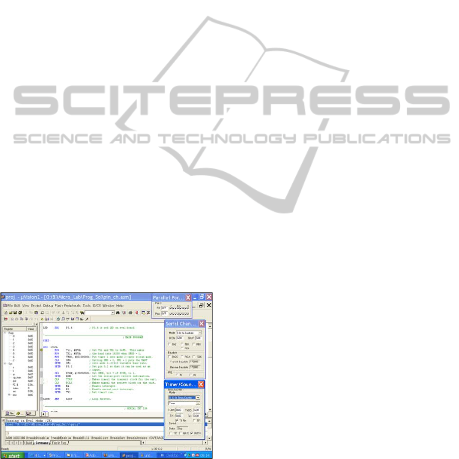
The simulator/debugger allows one to run a
program and examine the program as it executes. As
shown in Figure 1, one can simulate using most of the
ADuC841’s peripherals – though using some of the less
standard non-8052 peripherals can be something of a
challenge. (It can be difficult to simulate complex input
to the analog to digital converter, for example.)
Figure 1: The IDE simulator / debugger.
5 WHY WE USE VIRTUAL
MICROCONTROLLERS
At present, approximately 100 students are required to
participate in the microcontroller laboratory every year.
It would probably be best to have students work alone
and to give each student a microcontroller to work
with. In practice, our students work in pairs, and while
they are in the lab they have access to one of the
approximately 25 development kits. (The lab is run in
several sections.) For a variety of reasons, the labs are
not freely accessible to the students outside of class
time, so students have access to actual development
kits for a period of about three hours each week.
Students work in pairs for a variety of reasons.
Working in this way teaches them how to work in a
team. It also keeps the cost of the course within
reasonable limits by requiring fewer instructors. (In
order to see to it that the students are learning proper
programming practices, all programs are checked and
corrected. By having the students work in pairs, fewer
instructors can take care of the grading.)
The demo version of the Keil uVision4 IDE is
freeware. It is given out with the ADuC841 evaluation
kits, and it is available on Keil's website
(https://www.keil.com/demo/eval/c51.htm). By using
virtual microcontrollers – by using the IDE’s simulator
and debugger – we are able to provide each student
with his or her own microcontroller. Students can work
on their virtual microcontroller when and where it suits
them. Because the program is free, every student can
have a “virtual microcontroller.”
A signal advantage of the IDE is that it gives the
user easy access to many things to which there would
otherwise be no (easy) access. If a student wants to
learn how an arithmetic command works, it is simple to
program the IDE to use the command. Because the IDE
allows the user to look at all of the microprocessor’s
registers, the user can quickly find out just how a
command affects the microprocessor. This is something
that is much more easily done with and IDE than with a
true microprocessor. Given all of its advantages, why
not make a course that only uses “virtual
microcontrollers?”
6 THE PROBLEMS WE HAVE
EXPERIENCED WITH THE
VIRTUAL
MICROCONTROLLERS
There are several problems with using a virtual
microcontroller. As with all virtual equipment, there is
a danger that the user will not understand which parts
A"PARTIALLYVIRTUAL"MICROCONTROLLERLABORATORY
339

of the equipment being used are real and which parts
are virtual. Additionally, there are often actual
problems with the virtual systems; there are places that
the virtual system does not faithfully mimic the
physical system.
6.1 Problems with any IDE
Years ago, when designing the lab, we had to decide
what environment to use when programming. Initially,
we had the students write program using a very simple
editor (either Notepad or Edit). We had the students
compile the program using a separate compiler, and we
had them download the programs using a separate
downloader provided by Analog Devices. We did this
to help the students understand what the role of each
component was.
Because professionals generally use IDEs, after a
year or two we changed the structure of the lab
somewhat. We started off using separate programs, but
after a few weeks we had the students use the IDE. In
this way the students got used to thinking about the
roles of each of the separate programs and were
exposed to a reasonably standard IDE.
Several years ago, we found that Windows would
not allow us to use the older style programs, and we
started using the IDE exclusively. The disadvantage of
the increased use of the IDE, of the virtual system, is
that some of the students have a hard time determining
which of their commands are going to control the
virtual system and which are commands that are,
fundamentally, commands to the microcontroller.
Additionally, using an IDE, with all its many menus,
can cause a student to assume that using a
microcontroller is much more complicated than is
actually the case. We spend quite a bit of time trying to
dispel this illusion. At the beginning of the course, we
make almost no use of the advanced features provided
by the IDE. After the students understand the
microcontroller, we give a fairly detailed description of
the IDE and its features. In this way, the students learn
to distinguish between the microcontroller and the
debugger provided by the IDE.
6.2 Problems with our Virtual
Microcontroller
There is a second problem with using the IDE, the
virtual microcontroller – it does not always simulate
the microcontroller 100% faithfully. This problem is
(predictably) most severe when one is using features
that are not used that often or when there is a somewhat
complicated interaction between the program one is
writing and the hardware that one is trying to control.
All of the examples here are from our experience using
uVision3 V3.33.
Users of the 8052 will be familiar with the “read-
modify-write” commands (MC51 user’ s guide). When
such commands are used to read and modify values of
pins of an I/O port, they read and write to the input
latch to the I/O port and they do not “look at” the
voltage currently “seen” by the port (shown in Fig. 1).
Most other commands look at the current voltage seen
by the port.
The command JBC PM.N, label, which causes
the microcontroller to examine the N
th
pin of the M
th
I/O port, jump if the bit is a one and clear the bit, and
continue if the bit is a logical zero, is a read-modify-
write command. This command ought to look at the
value of the latch connected to this pin’s input. (That is,
it ought to react to the last value written to PM.N.) On
the actual microcontroller, this is exactly what happens.
The IDE’s simulator is rather easy to use, and it is
possible to tell the simulator that a bit’s latch is set –
that the last input to the pin was a logical one – but the
voltage on the pin is actually 0V. If one does this, then
even when using the JBC command, which ought to
look at the value of the latch, the command looks at the
actual (simulated) voltage on the pin and behaves in a
fashion that is neither consistent with the commands
definition nor with what the microcontroller actually
does. A student using the IDE is likely to be very
confused by this. (It is worth noting that in later
versions of the IDE this problem was corrected.)
Another interesting problem of this sort is
encountered when one uses Timer3, a timer that was
added to the ADuC841 and that can be used as the
clock for the 8052-standard UART. One of the registers
that controls this timer is the T3FD register. From our
experience, it seems that the permitted values of this
register are not all the values that one can write to the
register. When one writes an illegal value, the IDE
shows the microcontroller working as “it ought to”
when the microprocessor actually works in a somewhat
different fashion.
A student who uses the IDE might confuse him or
herself by trying to watch how the ADuC841
physically transmits data by either using the parallel
port dialog box (shown in Fig. 1) to watch the pin on
which the data leaves the ADuC841 – which is
physically the same pin that is used by pin 1 of port 3,
P3.1 – or by using the simulated logic analyzer
provided by the IDE to watch P3.1. Unfortunately,
neither of these methods will actually allow the student
to see how the UART works. Though a ‘scope probe
held to P3.1 will show the student the relevant voltages,
the IDE does not consider the UART’s transmit pin and
P3.1 to be the same.
Years ago we used the ADuC812 in our lab. This
microprocessor is very similar to the ADuC841, but we
experienced an interesting anomaly with the ADuC812
that does not exist with the ADuC841. When a program
was run after being directly downloaded from the IDE
CSEDU2012-4thInternationalConferenceonComputerSupportedEducation
340

to the ADuC812, sometimes the program would run
when it should not have. This would happen because
the ADuC812 does not finish a download with all of its
registers reset to their default values (Analog Device
Technical notes). In particular, it leaves a timer running
that is turned off after a reset. Students would forget to
turn on the timer in their program, would find that their
program worked on the microconverter but not in
simulation, and would hand in the programs not
understanding what had happened. A somewhat
different problem with our IDE is how it simulates non-
ADuC devices. The IDE has the ability to simulate the
“other side” of a UART. One can ask the IDE to open a
window that behaves very much like the Windows
“HyperTerminal” program that allows one to
communicate using the (virtual) P.C.’s (virtual) serial
(COM) port. The problem with the window opened by
the IDE is that it automatically adjusts itself to
whatever baudrate the user has, in fact, selected. If the
user meant to select a baudrate of 19,200 symbols/sec
but in fact selected 1,200 symbols/sec, the
“HyperTerminal” window will show perfect
communications. When the user downloads the
program to the microcontroller, it may take a fair
amount of time for him/her to realize where the mistake
was. Here one cannot say the simulator did not work
correctly. It worked correctly but allowed the user to
fool him or herself.
7 LESSONS WE HAVE LEARNED
After working with various simulation tools, one
realizes that they have advantages and disadvantages.
The simulation tools may be more accessible than the
physical system being simulated is. The simulation
tools may allow one to observe things that would
otherwise be difficult or impossible to observe. The
tools may also be less expensive than the physical
system. For these reasons one uses the tools.
When one uses simulation tools intensively, one
realizes that they must be considered a separate type of
“equipment.” Just as standard physical systems have
their personalities, their quirks, so do simulators and
virtual equipment. During an engineer’s working
lifetime, the engineer will have to learn to work with
many types of equipment, and it will be necessary to
understand the idiosyncrasies of each piece of
equipment.
An experienced engineer should not have a problem
distinguishing between the properties of a simulator
and the properties of an actual piece of equipment.
When working with students, however, it is not as
certain that the students will manage to make the
distinction. For this reason great care must be exercised
when running a lab on equipment other than the actual
industry-standard equipment.
In our microcontroller lab, much effort is expended
in order to help the students understand what a “virtual
microcontroller” is and what a real microcontroller is.
As long as we succeed in making that distinction clear,
we are helping our budding engineers understand the
tools of the trade – both “virtual equipment” and “real”
equipment. That is, of course, our goal.
ACKNOWLEDGEMENTS
Many people have contributed to the microcontroller
lab over the years. We are particularly grateful to Prof.
Aryeh Weiss of Bar Ilan University who has supported
the lab from its outset and to the members of our team
– Messrs. Tamir Rozental, Shai Tamir, Amikam
Borkowski, Amihai Meiri, and Aviram Gur.
REFERENCES
Analog Devices, “MicroConverter Technical Note -
uC004 Understanding the Serial Download Protocol,”
Analog Devices, Inc., Norwood, MA, 2001.
Barbosa, A. Lula, B. and Lima, A. F., 2007. Symbolic and
numeric quantum circuit simulation, Proceedings of
the 1st International Conference on Quantum, Nano,
and Micro Technologies (ICQNM'07), pp. 6-10.
Chaturvedi, S. K. and Akan, O., 2006. Simulation and
Visualization Enhanced Engineering Education,
International Mechanical Engineering Education
Conference, Beijing, China.
Davidovitch, L. Parush, A. and Shtub, A., 2006.
Simulation-based Learning in Engineering Education:
Performance and Transfer in Learning Project, Journal
of Engineering, American Society for Engineering
Education, Oct., pp. 289-300.
Donzellini, G. and Ponta, D., 2007. A Simulation
Environment for e-Learning in Digital Design, IEEE
Transactions on Industrial Electronics, vol. 54, no. 6,
pp. 3078-3085.
Engelberg, S. 2012. ADuC841 Microcontroller Design Manual:
From Microcontroller Theory to Design Projects, Circuit
Cellar, Vernon, CT, to appear.
Feisel, L. D. and Rosa, A. J. 2005. The role of the
laboratory in undergraduate engineering education,
Journal of Engineering Education, vol. 94, no. 1, pp.
121–130.
Hundhausen, C. D. and Brown, J. L. , 2005. What you see
is what you code: a radically dynamic algorithm
visualization development model for novice learners,
Proceedings of the 2005 IEEE Symposium on Visual
Languages and Human-Centric Computing
(VL/HCC'05), pp. 163-170.
Ma, J. and. Nickerson, J. V., 2006. Hands-on, simulated,
and remote laboratories: A comparative literature
A"PARTIALLYVIRTUAL"MICROCONTROLLERLABORATORY
341

review, ACM Computer Survey, vol. 38, no. 3, pp. 1-
24.
MCS51 Microcontroller Family User’s Guide, Intel Corp., Mt.
Prospect, IL, 1994, p. 3-9.
Price, B. A. Baecker R. M. and Small, I. ,1998. An
introduction to software visualization. In J. Stasko, J.
Domingue, M. Brown & B. Price (Eds.), Software
Visualization, pp. 3-34, Cambridge, MA: MIT Press.
Swaak J. and de Jong, T., 2001. Discovery simulations and
the assessment of intuitive knowledge, Journal of
Computer Assisted Learning, vol. 17, no. 3, pp. 284-
294.
Veermans, K. H. de Jong, T. van Joolingen, W.R., 2000.
Promoting self directed learning in simulation based
discovery learning environments through intelligent
support. Interactive Learning Environments, no. 8, pp.
229-255.
Yehezkel, C. Ben-Ari, M. and Dreyfus, T., 2007. The
contribution of visualization to learning computer
architecture, CSE on Special Issue on Teaching
Hardware-software, vol. 2, no. 17, pp. 117-127.
CSEDU2012-4thInternationalConferenceonComputerSupportedEducation
342
