
SELF-ADAPTIVE NOC POWER MANAGEMENT
WITH DUAL-LEVEL AGENTS
Architecture and Implementation
Syed M. A. H. Jafri
1,2,3
, Liang Guang
2,3
, Axel Jantsch
1
, Kolin Paul
4
, Ahmed Hemani
1
and Hannu Tenhunen
1,2,3
1
Royal Institute of Technology, Stockholm, Sweden
2
University of Turku, Turku, Finland
3
Turku Centre for Computer Science, Turku, Finland
4
Indian Institute of Technology Delhi, Delhi, India
Keywords:
DVFS, Agent based Design, Hardware/Software Co-design, Multiprocessor Architectures, Low-power
Design.
Abstract:
Architecture and Implementation of adaptive NoC to improve performance and power consumption is pre-
sented. On platforms hosting multiple applications, hardware variations and unpredictable workloads make
static design-time assignments highly sub-optimal e.g. in terms of power and performance. As a solution to
this problem, adaptive NoCs are designed, which dynamically adapt towards optimal implementation. This pa-
per addresses the architectural design of adaptive NoC, which is an essential step towards design automation.
The architecture involves two levels of agents: a system level agent implemented in software on a dedicated
general purpose processor and the local agents implemented as microcontrollers of each network node. The
system agent issues specific instructions to perform monitoring and reconfiguration operations, while the local
agents operate according to the commands from the system agent. To demonstrate the system architecture,
best-effort power management with distributed voltage and frequency scaling is implemented, while meeting
run-time execution requirements. Four benchmarks (matrix multiplication, FFT, wavefront, and hiperLAN
transmitter) are experimented on a cycle-accurate RTL-level shared-memory NoC simulator. Power analysis
with 65nm multi-Vdd library shows a significant reduction in energy consumption (from 21 % to 36 %). The
synthesis also shows minimal area overhead (4 %) of the local agent compared to the original NoC switch.
1 INTRODUCTION
The many-core SoC (System-on-Chip) era has come
due to the constant shrinking of transistor sizes. The
state-of-the-art Network-on-Chip (NoC), as the most
promising on-chip parallel communication architec-
ture, has a large number of integrated components
(Truong et al., 2009; Howard et al., 2011). In terms
of technology scaling, thousand-core processor will
be feasible in the near future (Asanovic et al., 2006).
The design of massively parallel NoC is strongly
challenged by the hardware and workload variations.
The hardware variations are generally characterized
by PVT (process, voltage, and thermal) variations
(Borkar et al., 2003), which all result in instability
and unpredictability of the hardware performance, in
terms of functional correctness, timing and power co-
nsumption. The worst-case design based on the
biggest deviations requires large design margin, lead-
ing to low performance or increased power overhead
(Rabaey, 2007). In addition to these hardware vari-
ations, the run-time workloads on the NoC are also
highly diverse and unpredictable at the design time.
Scientific applications, radio processing, media pro-
cessing, and various other types of applications are
expected on future many-core systems, for instance
smartphones (van Berkel, 2009). It is infeasible to
rely solely on design-time configuration for potential
workloads, especially when the mapping and schedul-
ing are likely to be dynamic as well.
To deal with the hardware variations and unpre-
dictable workloads, future NoCs should be made
“Self-Adaptive” (Salehie and Tahvildari, 2009)
1
its
status (self-awareness) and reconfigure system pa-
450
M. A. H. Jafri S., Guang L., Jantsch A., Paul K., Hemani A. and Tenhunen H. (2012).
SELF-ADAPTIVE NOC POWER MANAGEMENT WITH DUAL-LEVEL AGENTS - Architecture and Implementation.
In Proceedings of the 2nd International Conference on Pervasive Embedded Computing and Communication Systems, pages 450-458
DOI: 10.5220/0003942204500458
Copyright
c
SciTePress

rameters (self-adaptation), in order to achieve the ex-
pected performance goals or seek possible optimiza-
tion. Our previouswork (Guang et al., 2010) proposes
a hierarchical agent monitoring system architecture
for generic parallel embedded system. It suggests that
several level of controllers shall be added with hier-
archical scope and priorities, to provide both coarse
and fine-granular observability and reconfigurability.
Conceptually, agents are monitoring and reconfigu-
ration functions, which can be realized as software,
hardware or a hybrid of both. The conventional NoC
platform, including data, memory and communica-
tion, is considered resources supervised by the agents.
This work presents the essential architectural-
level support for hierarchical agent monitored NoC, in
order to enable the design automation of self-adaptive
systems. In particular, the system agent, which de-
termines the adaptive policy for the whole NoC, is
implemented as a software agent, with specific in-
structions designed for monitoring and reconfigura-
tion operations. The local agents, which monitor and
reconfigure the local resources based on the command
from the system agent, are implemented as micro-
controllers for each network node. The communi-
cation between agents are implemented on existing
NoC channels. The agents are fully integrated in a
RTL-level cycle-accurate NoC simulator with Leon 3
processing elements and distributed shared memory.
The system architecture is demonstrated with
best-effort per-core DVFS (dynamic voltage and fre-
quency scaling), as a representative algorithm for
self-adaptive power and energy management. The
whole system is synthesized with 65nm multi-Vdd li-
brary. Four real benchmarks (matrix multiplication,
FFT, wavefront, and hiperLAN transmitter) are exper-
imented with power and energy measurement to show
the effectiveness of the approach. The software and
hardware overheads are evaluated to show the scala-
bility of the system architecture.
2 RELATED WORK
Most previous works are focused on specific algo-
rithms or monitoring goals, including power con-
sumption, thermal management or dependability is-
sues. Works on systematic approaches of generic
monitoring and reconfiguration architecture are quite
limited.
(Ciordas, 2008) proposes a monitoring-awaresys-
tem architecture and design flow for NoC. This
1
Although this paper is targeted at self-adaptive soft-
ware, the general concept applies to the whole system.
work focuses on hardware-based probes for transac-
tion debugging and QoS (Quality-of-Service) provi-
sion. Our work, however, presents a SW/HW (soft-
ware/hardware) co-design approach to the monitoring
and reconfiguration, with services for non-functional
design goals, such as power and energy consumption.
(Sylvester et al., 2006) is an early work pre-
senting an adaptive system architecture, ElastIC, for
self-healing many-core SoC. Each core is designed
with observable and tunable parameters, for instance
power monitors. A centralized DAP (diagnostic and
adaptivity processing) unit dynamically tests and re-
configures cores of degraded performance. However
(Sylvester et al., 2006) does not explore in detail the
architecturalsupport or the implementation of the sys-
tem architecture.
A two-level controlling architecture is presented
in (Dafali and Diguet, 2009). A centralized configu-
ration manager determines the management policies
of the whole network, while each local manager de-
cides the reconfiguration based on the management
policies. (Dafali and Diguet, 2009) is only focused on
the design of self-adaptive network interface, without
the system-scale discussion on power efficiency nor
dependability.
Our previews work (Guang et al., 2010) proposes
the functional overview of hierarchical agent mon-
itoring design paradigm. This work presents the
instruction-level architectural design and implemen-
tation specifically for NoC platforms. In particular,
both the system agent and local agents are designed
and implemented (down to the RTL-level) on a con-
crete NoC platform (Section 5.2), while (Guang et al.,
2010) only indicates the general principles of func-
tional partition and implementation manner (software
or hardware) of agents.
(Hoffmann et al., 2010) presents a so-called
”heartbeat framework” or application to notify its per-
formance “als and behaviors t” the platform observer,
and obtain actual performance. The progression of
the application is symbolized as a heartbeat. By mon-
itoring the intervals between heartbeats, the platform
observer and the application can be aware of the sys-
tem performance. We integrate this application label-
ing approach into our system architecture, where the
system agent monitors the application execution time
by checking the labeled timestamps.
Compared to these existing works, this paper
makes several major contributions:
• Dual-level agent monitoring with SW/HW co-
design and synthesis is a scalable approach for
many-core systems with various monitoring and
reconfiguration services.
• Instruction-level architectural design enables the
SELF-ADAPTIVE NOC POWER MANAGEMENT WITH DUAL-LEVEL AGENTS - Architecture and Implementation
451

Agent Layer
Application with Timestamps
Application_start();
...
monitored_event();
...
...
monitored_event();
...
...
Application_end();
Mapper,
Scheduler
Power Management
Local
Agent
Node
Local
Agent
Node
delegate
Dedicated processor in NoC
(only runing agent function)
Wrapper
microcontroller
R
R
R
R
R
R
R
R
R
R
R
R
NoC Backbone
microcontroller
System Agent
Figure 1: System overview of hierarchical agent monitored
NoC.
system architecture to be integrated into NoC de-
sign flow.
• RTL-level full system implementation (digital
parts) provides accurate power and area analysis
with 65nm multi-Vdd library.
3 SYSTEM OVERVIEW
To achieve self-adaptive NoC, we propose that an
intelligence layer shall be added upon the conven-
tional NoC system architecture (Fig. 1). The layer is
composed of one system agent, which is the general
manager of all monitoring and reconfiguration oper-
ations, and distributed local agents, which are dele-
gates of the system agent to actuate the operations.
In the meantime, the application shall be labeled with
timestamps to enable agent’s awareness of applica-
tion progression (Section 4.1). The joint efforts of
the system and local agents realize the adaptivity of
the system, for example autonomoustradeoff between
power/energy and timing requirements of the applica-
tion.
In terms of function, the agent layer is orthogonal
to the data computation. The underlying NoC back-
bone, regardless of the exact implementation (topol-
ogy, routing, flow control or memory architecture),
performs the conventionaldata communication, while
the agent subsystem monitors the computation and
communication. The separation of agent services pro-
vides portability of the system architecture to differ-
ent NoC platforms, thus leading to improved design
efficiency.
Application_start();
...
...
Monitored_event_start();
...
...
Monitored_event_end();
...
...
...
Application_end();
Memory_write(memory_location1)
On the system agent’s memory space
Memory_write(memory_location4)
Application labelled with Timestamps
Memory_write(memory_location2)
Memory_write(memory_location3)
Implementation
Figure 2: Labeling timestamps in the application.
4 ARCHITECTURAL DESIGN
The functions of system and local agents need to be
implemented as either software instructions, micro-
controllers or hardware components. For software
agents, instructions are needed for monitoring and
reconfiguration operations. For microcontroller or
hardware-based agents, the micro-architecture to in-
terface with the software agent and the local resources
needs to be designed.
4.1 Application Timestamps
To enable the monitoring of applications, meta-data
needs to be added in the instructions, for instance to
denote the progression of the application. Fig. 2 gives
an example of adding timestamps in the applications.
In particular, the starting and finishing time of the ap-
plication and the critical sections are labeled with spe-
cial instructions, so that the occurrence of these events
can be monitored by the system agent.
As one alternative, these timestamps labeling in-
structions are implemented as memory write instruc-
tions. Specific data shall be written to a memory lo-
cation of the system agent, to notify the occurrence
of the event. The allocation of the memory address
can be performed in the compilation process, which
is beyond the scope of the paper.
4.2 System Agent
The system agent works as the “general manager”
for monitoring and reconfiguration services. Depen-
dent on the design requirement, the system agent shall
be responsible for task mapping, process scheduling,
run-time power management and fault tolerance. Due
to such diversity, the system agent is implemented as
a dedicated processor in NoC, so that the agent func-
tions can be reloaded dynamically.
Generally speaking, the system agent monitors the
progression of applications and the system parame-
PECCS 2012 - International Conference on Pervasive and Embedded Computing and Communication Systems
452

Parallel processes:
Check ( monitored_parameter1 );
...
Check ( monitored_parameter2 );
...
blocking_read( memory_location1)
Software Instruction
Check_Application_Start();
...
Check_Application_End();
...
Implementation
Process 1:
blocking_read(location_parameter1);
reconfiguration1(paramter1);
Process 2:
blocking_read(location_parameter2);
Reconfiguration2(parameter2);
Memory_write(command1);
Memory_write(command2);
Reconfiguration1 ( monitored_parameter1);
Reconfiguration2 ( monitored_parameter2);
blocking_read( memory_location2);
Figure 3: Monitoring and reconfiguration software on sys-
tem agent.
ters, and reconfigures the system according to cer-
tain adaptive algorithms. In detail, the system agent
first checks the start of the application (or a frame in
streaming applications), which is implemented as a
blocking memory read. The application will label the
timestamps when it starts (Section 4.1). To monitor a
certain parameter after the application starts, the sys-
tem agent first issues a command to check the run-
time value of the parameter. The command is written
to the memory location of the intended network node,
so that the corresponding local agent will receive the
command. In the similar manner, the system agent
can issue any number of parameter-checking com-
mands, which are all implemented as non-blocking
memory writes. Afterwards, the system agent waits
on the report of the monitored parameters by the cor-
responding local agents (as memory writes; Section
4.3). These waiting operations are implemented as
blocking reads. When a certain read completes, the
system agent performs reconfiguration based on the
run-time parameter values. The waiting of multiple
parameters are parallel processes, since the parame-
ters may be returned in random orders. When all re-
quired monitoring and reconfiguration operations are
finished, the system agent waits for the completion of
the application. However, in case one monitored pa-
rameter is the execution time of an application frame,
the monitoring operation may be finished after the
frame ends.
Table 1 lists the detailed C instructions (on a Leon
3 processor) on the system agent to implement moni-
toring and power management.
4.3 Local Agents
Local agents are distributed microcontrollersattached
to each network node. They actuate the monitoring
and reconfiguration operations as commanded by the
system agent. In particular, each local agent, upon
receiving the monitoring commands from the system
agent, reads the required parameters from the local re-
source (Fig. 4). Similarly, when receiving a reconfig-
uration command, it actuates the reconfiguration, for
Network
Node
System Agent
Local agent
Microcontroller
Monitor commands
e.g. get_load
load
load
wrapper
Clk_sel
Vol_sel
Other parameters,
e.g. Packet latency
Reconfiguration
commands e.g.
DVFS_change
Figure 4: Schematics of local agent and its interfaces to
system agent and network node.
instance by setting the power switch and frequency
generator. The interfaces to various parameters for
monitoring and reconfiguration are hardwired, so that
the network node can be used as a modularized com-
ponent integrable into any NoC systems.
The implementation of local agents as microcon-
troller considers the tradeoff between performance,
flexibility and overhead. A software-based agent,
i.e. the system agent, has the largest flexibility
with higher operation latencies and larger area over-
head. Purely hardware-based monitoring and recon-
figuration circuit provides the fastest operation speed,
while changing its function requires reconfiguration
of the circuit itself. Microcode approach is a suitable
tradeoff between software and hardware-based design
(Chen et al., 2010), for local agents whose operations
are strictly based on the commands from the system
agent.
4.4 Architectural Integration
The agent intelligence layer is the architectural inte-
gration of the system agent and the distributed local
agents, with timestamp-labelled application (Fig. 5) .
The application programmers specify the times-
tamps of monitored events in the application, for in-
stance the starting/end times of each frame. The sys-
tem designers write software instructions for moni-
toring and reconfiguration operations with high-level
abstraction. These operations are sent to and imple-
mented by local agents, which are microcontrollers
of each network node. The wrapping of the local
agent and the resource is design specific. For instance,
if parameters from both the processing element and
the router are needed for the monitoring and recon-
figuration, the local agent is attached to the whole
node. Since the monitoring and reconfiguration are
infrequently issued compared to data communication
(Ciordas et al., 2008), we can reuse the existing NoC
interconnect for inter-agent communication. In par-
ticular, the inputs from a processing element and the
SELF-ADAPTIVE NOC POWER MANAGEMENT WITH DUAL-LEVEL AGENTS - Architecture and Implementation
453
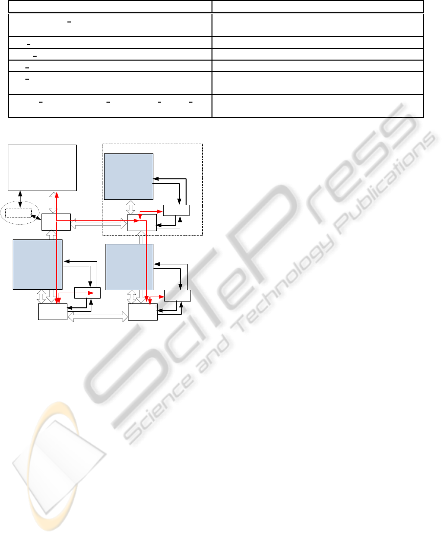
Table 1: Experimented instructions for monitoring and power management on system agent (a Leon 3 processor).
Instruction Function
wait(memory location) Wait for the occurrence of an event (the application
writes the corresponding memory location)
get load(row, column, switch) Check the run-time workload of a particular switch
reset load(row, column, switch) Refresh the workload record of a particular switch
set window(row, column, switch, windowsize) Set the monitoring window
set priority(row, column, switch, priority) Set the priority of agent command in the network
arbitration
DVFS change(memory location, clk sel, vol sel) Change the voltage and frequency of a particular
switch (denoted by the memory location)
System Agent
Management Sofware
Processing element
Router
Application_start;
......
Start
(monitored_event1);
......
Local agent
Local
agent
Router
check(paramter1);
check(parameter2);
Reconfiguration1(parameter1);
Reconfiguration2(parameter2);
...
Check
parameters
Wrapper
......
End
(monitored_event1);
......
Router
Router
Inactive
Inter-agent communication
Commands/
Monitored data
reconfigure
Local
agent
Check
parameters
reconfigure
Local
agent
reconfigure
......
......
Application_end;
Figure 5: Integrating hierarchical agents as an intelligence
layer.
local agent share the same router port, with the agent
having the higher priority in arbitration.
Due to the SW/HW co-design and modularized ar-
chitectural integration, the agent intelligence layer is
highly scalable. The local agent wrapper can be ap-
plied to any NoC node (or a particular NoC compo-
nent, e.g. router), and be used as a “building brick”
to construct a NoC of any size without incurring ad-
ditional overhead. The software-based system agent,
on the other hand, can be written with various mon-
itoring and reconfiguration instructions as needed for
the application.
5 SELF-ADAPTIVE POWER
MANAGEMENT
To demonstrate the effectiveness and overheads of us-
ing dual-level agents, we have used best-effort per-
core DVFS on the existing NoC platform. Based on
the specified parameters (e.g. peak load and aver-
age load), the local agents trace run-time system in-
formation. Upon the request of the system agent,
they return the recorded values. Depending upon
the provided information and the application perfor-
mance constraints, the system agent adjusts the volt-
age and/or frequency to optimize the power and en-
ergy consumption.
5.1 Best-effort Per-core DVFS (BEPCD)
The adaptive power management using distributed
DVFS with run-time application performance moni-
toring, abbreviated as BEPCD, is illustrated in Fig.
6. P, S, LT, F and Ts represent processor, switch,
low traffic switches (the switch with the lowest work-
load), switch frequency and threshold time (the appli-
cation latency), respectively. The terms inside paren-
thesis represent the function to be performed on the
entity to the left (e.g. P(any) starts? means if any
of the processors starts). Simply put, the process is
performed in three steps: (i) the initialization of volt-
age and frequency of each switch and the setting of
application latency requirement, (ii) run-time tracing
of the workload of each switch and the application la-
tency (Section 4.2), (iii) if the latency is lower than
the constraint, DVFS is applied to the switch with the
lowest workload.
5.2 NoC Infrastructure
An in-house cycle-accurate RTL-level NoC simula-
tor (Jean-Michel Chabloz, 2012) is used for exper-
iments. The simulator is based on Nostrum archi-
tecture (Nostrum, 2011), with X-Y dimension-order
routing and deflection routing (when contention is en-
countered). Each processing element is a Leon 3 pro-
cessor as a fully synthesizable IP block. Distributed
shared memory is used, with distributed memory con-
troller attached to each network node. Each router
PECCS 2012 - International Conference on Pervasive and Embedded Computing and Communication Systems
454

Figure 6: Per-core DVFS for best-effort power management
with run-time performance monitoring.
or processing element can be configured with differ-
ent voltage and frequency values. Such a module is
equipped with its own clock generation unit, which is
fully implemented in the simulator. It is also equipped
with the interfaces (powerswitch) to connect to differ-
ent power grids for run-time voltage scaling, as pre-
sented in (Truong et al., 2009). The power switch is
only emulated as a latency module since it is an ana-
log circuit. A conservative voltage switching delay of
27ns (Jean-Michel Chabloz, 2012) is set in the sim-
ulator, which is larger than the delay measured on a
real NoC prototype ((Truong et al., 2009); less than
20ns). To support such fine-grained power island,
the NoC infrastructure adopts globally ratiochronous
locally synchronous (GRLS) clocking (Chabloz and
Hemani, 2010). In particular, all clocks on the chip
run at frequencies which are submultiple of a certain
F
H
. This restriction achieves a significant simplifica-
tion in the implementation of synchronizes with low
latency and overhead. Synchronizing registers (4 flip-
flops per data line) are used between two different
clock regions to reduce metastability, as suggested in
(Chabloz and Hemani, 2010).
5.3 Experiment Setup
To identify the voltages and their corresponding sup-
ported frequencies, the switches were synthesized us-
ing Synopsys design compiler for 65 nm multi-Vdd
technology (Table 2). The technology supports volt-
ages from 1.1 V to 1.32 V. The synthesis results reveal
that the routers are capable of supporting up to 300
MHz frequency at 1.32 V and up to 200 MHz fre-
quency at 1.1 V. Based on GRLS clocking in the NoC
platform (Section 5.2), the allowable frequencies are
300, 200, 100, 50, 40, and 20 MHz (exact divisors of
F
H
= 600MHz, least common multiplier of 300MHz
and 200MHz).
Table 2: Voltage frequency pairs.
Voltage Frequency Timing constraints
(V) (MHz)
1.32 400 violated
1.32 300 met
1.32 200 met
1.1 400 violated
1.1 300 violated
1.1 200 met
1.1 100 met
1.1 50 met
1.1 40 met
1.1 20 met
Four applications (matrix multiplication, FFT,
wavefront, and hiperLAN transmitter) are mapped on
a 3x3 mesh-based NoC. The absence of DSPs in exist-
ing NoC platform prevents us from meeting the dead-
line (4 µs/frame) of hiperLAN transmitter. Thus we
set the deadline as the minimal latency of the appli-
cation on the NoC platform (39 µs) , when all routers
are configured with the highest frequency.
To analyze the power and energy consumption, the
switching activity files are generated for each applica-
tion from Cadence NCSim. The NoC routers are syn-
thesized using 65 nm multi-Vdd library. The power
analysis is performed by Synopsys design compiler
on the synthesized NoC routers with the generated
switching activity files.
5.4 Experiment Result
Four benchmarks (matrix multiplication, FFT, wave-
front, and hiperLAN) were experimented with
BEPCD algorithm. Initially, the system agent as-
signed max frequency (300 MHz) and voltage (1.32
V) to all switches. At each iteration, the application
execution time was monitored and if it did not violate
the timing deadline, the next lower voltage/frequency
pair from Table 2 was assigned to the lowest traffic
switch (in terms of peak load in a time window of 40
cycles).
Tables 3, 4, 6, and 5 show the energy and power
savings of each of the four benchmarks. In the ta-
bles, the second column shows the switch number
which changes its voltage/frequency followed by ”f”
or ”vf”. ”f” indicates a frequency change, while ”vf”
shows that both the voltage and frequency change.
The power and energy trends for each of the four
applications are clearly depicted in Figure 7. It is seen
that as a consequence of BEPCD, the NoC quickly it-
erates towards the minimum power for each of the ap-
plication. If the targeted switch is present in the crit-
ical path, as expected, the application execution time
SELF-ADAPTIVE NOC POWER MANAGEMENT WITH DUAL-LEVEL AGENTS - Architecture and Implementation
455

Table 3: Energy and power savings for matrix multiplica-
tion.
Iteration Switch Time Energy Power Energy saving Power savings
(ns) (mJ) mW % %
1 - 105834 1.73 16.35 0 0
2 1vf 105834 1.67 15.84 3.11 3.11
3 3vf 106808 1.26 11.84 26.90 27.56
4 3f 107415 1.21 11.31 29.78 30.82
5 3f 112134 1.25 11.20 27.39 31.46
6 3f 116373 1.27 10.99 26.07 32.76
7 1f 101815 1.11 10.97 35.46 32.91
8 2vf 108774 1.92 16.96 31.11 32.97
9 2f 113100 1.17 10.41 31.97 36.34
10 2f 111134 1.15 10.38 33.32 36.50
11 2f 111467 1.57 10.38 33.12 36.53
Table 4: Energy and power savings for FFT.
Iteration Switch Time Energy Power Energy saving Power savings
(ns) (mJ) mW % %
1 - 381615 17.40 45.61 0 0
2 3vf 381615 15.87 41.60 8.78 8.78
3 3f 381615 15.67 41.07 9.95 9.95
4 3f 381616 14.10 36.96 18.95 18.95
5 1vf 377320 13.66 36.21 21.49 20.59
6 1f 430525 15.54 36.11 10.68 20.83
7 1f 381616 16.69 35.89 21.29 21.29
8 2vf 381616 13.69 35.89 21.29 21.29
9 2f 381154 13.68 35.89 21.39 21.29
10 2f 376549 12.01 31.89 30.99 30.06
(AET) increases with a decrease in voltage/frequency
(iteration 3 to 6 and 7 to 9 in Table 3, iteration 2 and 4
in Table 6). The AET remains unaffected if the switch
does not come in the critical path (Table 5, iteration 6
to 13 Table 6). In some situations, the memory con-
tention is reduced with voltage/frequency decrease,
then AET may also decrease (iteration 7 and 10 Ta-
ble 3, iteration 7 and 10 in table 4, and iteration 3 in
Table 6 ).
The BEPCD performs iterations only till the ap-
plication meets deadline. To cater for the sudden
changes in time (iteration 6 in Table 4) resulting from
massive memory contention (iteration 6 Table 4), the
algorithm performs an additional iteration to check if
a further reduction in frequency would reduce time.
If no reduction is encountered, switch is reverted to
original frequency and no further DVFS commands
are given. The plots confirm clearly significant ad-
vantages of our proposed strategy (from 21% to 33%
decrease in energy and from 21% to 36% decrease in
power consumption).
Table 5: Energy and power savings for HiperLAN.
Iteration Switch Time Energy Power Energy saving Power savings
(ns) (mJ) mW % %
1 - 39000 1.77 45.61 0 0
2 1vf 39000 1.62 41.60 8.78 8.78
3 3vf 39000 1.60 41.07 9.95 9.95
4 3f 39000 1.44 37.06 18.73 18.73
5 3f 39000 1.42 36.54 19.88 19.88
6 3f 39000 1.42 36.42 20.13 20.13
7 1f 39000 1.41 36.21 20.59 20.59
8 - 39000 1.40 35.90 21.29 21.29
9 - 39000 1.40 35.90 21.29 21.29
10 - 39000 1.40 35.90 21.29 21.29
11 - 39000 1.40 35.90 21.29 21.29
12 - 39000 1.40 35.90 21.29 21.29
Table 6: Energy and power savings for wavefront.
Iteration Switch Time Energy Power Energy saving Power savings
(ns) (mJ) mW % %
1 - 91970 1.51 16.50 0 0
2 3vf 110234 1.37 12.50 9.15 31.94
3 3f 106529 1.28 12.03 15.51 37.09
4 3f 110294 1.32 11.97 12.96 37.79
5 - 110294 1.32 11.97 12.96 37.79
6 - 110294 1.32 11.97 12.96 37.79
7 - 110294 1.32 11.97 12.96 37.79
8 - 110294 1.32 11.97 12.96 37.79
9 - 110294 1.32 11.97 12.96 37.79
10 - 110294 1.32 11.97 12.96 37.79
5.5 Overhead Analysis
To evaluate the overhead of the dual-level agent intel-
ligence layer, we need to analyze the area overhead
of microcontroller-based local agent (Fig. 4) and the
instruction overhead of software-based system agent
(Fig. 3).
At 300 MHz frequency with 1.32 V operating
voltage, Synopsys design compiler shows an area of
1459 µm
2
for each local agent, which is negligible (4
%) as compared to the router area (33806 µm
2
). The
local agent does not contribute to any timing over-
head as it is not present in the critical path of the
switch. Concerning the software overhead of the sys-
tem agent, it only amounts to 279 lines of C code on
Leon 3 processor for the BEPCD algorithm.
We can see from the overhead analysis that, dual-
level agent monitoring incurs minimal hardware area
overhead and software instruction overhead. Thus the
system architecture is scalable to large-sized NoCs
with a diversity of monitoring and reconfiguration
functions.
PECCS 2012 - International Conference on Pervasive and Embedded Computing and Communication Systems
456

Figure 7: Energy and power comparison for (a) matrix mul-
tiplication, (b) FFT, (c) wavefront, and (d) hiperLAN.
6 CONCLUSIONS AND FUTURE
WORK
We have presented the design and implementation of
a generic and scalable self-adaptive NoC architecture.
The system is monitored and reconfigured by dual-
level agents with SW/HW co-design and synthesis.
The system agent is implemented in software, with
high-level instructions tailored for issuing adaptive
operations. The local agent is attached to each net-
work node and implemented as a microcontroller. The
local agent provides tracing and reconfiguration of the
local circuit parameters, based on the run-time adap-
tation commands from the system agent. The dual-
level agents make a joint effort to achieve the perfor-
mance goals of the application, where the monitored
events are labeled with timestamps. The separation of
the intelligence layer from NoC infrastructure makes
the approach generic and improves the design effi-
ciency. The SW/HW co-design and synthesis effec-
tively reduces the hardware overhead while offering
flexibility for adaptive operations.
We demonstrated the effectiveness and the scal-
ability of the system architecture with best-effort dy-
namic power management using distributed DVFS. In
this case study, the application execution time and the
run-time workloads of all routers are directly moni-
tored by the agents. The router with the lowest work-
load will be switched to a lower voltage and/or fre-
quency when there is a positive slack of application
latency (per frame/stream). The experiments were
performed with four benchmarks (matrix multiplica-
tion, FFT, wavefront, and hiperLAN transmitter), on a
cycle-accurate RTL-level NoC simulator. With 65nm
multi-Vdd library for synthesis and power analysis,
we showed that the adaptive power management saves
up to 33% energy and up to 36% power. The hardware
overhead of each local agent is only 4% of a router
area.
In the future work, we will present a complete de-
sign chain for the system architecture, including ap-
plication mapping, scheduling followed by run-time
monitoring and reconfiguration. The inter-agent com-
munication shall also be provided with guaranteed
services.
REFERENCES
Asanovic, K., Bodik, R., Catanzaro, B. C., Gebis, J. J.,
Husbands, P., Keutzer, K., Patterson, D. A., Plishker,
W. L., Shalf, J., Williams, S. W., and Yelick, K. A.
(2006). The landscape of parallel computing re-
search: A view from berkeley. Technical report,
U.C.Berkeley.
Borkar, S., Karnik, T., Narendra, S., Tschanz, J., Ke-
shavarzi, A., and De, V. (2003). Parameter variations
and impact on circuits and microarchitecture. In Proc.
Design Automation Conference, pages 338–342.
Chabloz, J. M. and Hemani, A. (2010). Distributed dvfs
using rationally-related frequencies and discrete volt-
age levels. In Low-Power Electronics and Design
(ISLPED), 2010 ACM/IEEE International Symposium
on, pages 247 –252.
Chen, X., Lu, Z., Jantsch, A., and Chen, S. (2010). Support-
ing distributed shared memory on multi-core network-
on-chips using a dual microcoded controller. In Proc.
Design, Automation & Test in Europe Conf. & Exhibi-
tion (DATE), pages 39–44.
Ciordas, C. (2008). Monitoring-Aware Network-on-Chip
Design. PhD thesis, Eindhoven University of Tech-
nology.
Ciordas, C., Hansson, A., Goossens, K., and Basten, T.
(2008). A monitoring-aware network-on-chip design
flow. J. Syst. Archit., 54:397–410.
Dafali, R. and Diguet, J.-P. (2009). Self-adaptive network
interface (sani): Local component of a noc configura-
tion manager. In Proc. Int. Conf. Reconfigurable Com-
puting and FPGAs ReConFig ’09, pages 296–301.
Guang, L., Nigussie, E., Isoaho, J., Rantala, P., and Ten-
hunen, H. (2010). Interconnection alternatives for hi-
erarchical monitoring communication in parallel socs.
Microprocessors and Microsystems, 34(5):118–128.
Hoffmann, H., Eastep, J., Santambrogio, M. D., Miller,
J. E., and Agarwal, A. (2010). Application heartbeats
for software performance and health. In Proceed-
ings of the 15th ACM SIGPLAN symposium on Prin-
ciples and practice of parallel programming, PPoPP
’10, pages 347–348, New York, NY, USA. ACM.
Howard, J., Dighe, S., Vangal, S. R., Ruhl, G., Borkar,
N., Jain, S., Erraguntla, V., Konow, M., Riepen, M.,
SELF-ADAPTIVE NOC POWER MANAGEMENT WITH DUAL-LEVEL AGENTS - Architecture and Implementation
457

Gries, M., Droege, G., Lund-Larsen, T., Steibl, S.,
Borkar, S., De, V. K., and Van Der Wijngaart, R.
(2011). A 48-core ia-32 processor in 45 nm cmos us-
ing on-die message-passing and dvfs for performance
and power scaling. IEEE Journal of Solid-State Cir-
cuits, 46(1):173–183.
Jean-Michel Chabloz, A. H. (2012). Scalable Multi-
core Architectures, chapter PowerManagement Ar-
chitectureinMcNoC, pages 55–80. Springer Sci-
ence+Business Media, LLC.
Nostrum (2011). http://www.ict.kth.se/nostrum/.
Rabaey, J. M. (2007). Scaling the power wall: Revisiting
the low-power design rules. Keynote speech at SoC
07 Symposium.
Salehie, M. and Tahvildari, L. (2009). Self-adaptive soft-
ware: Landscape and research challenges. ACM
Trans. Auton. Adapt. Syst., 4:14:1–14:42.
Sylvester, D., Blaauw, D., and Karl, E. (2006). Elas-
tic: An adaptive self-healing architecture for unpre-
dictable silicon. IEEE Design & Test of Computers,
23(6):484–490.
Truong, D., Cheng, W., Mohsenin, T., Yu, Z., Jacobson,
A., Landge, G., Meeuwsen, M., Watnik, C., Tran, A.,
Xiao, Z., Work, E., Webb, J., Mejia, P., and Baas, B.
(2009). A 167-processor computational platform in
65 nm cmos. IEEE Journal of Solid State Circuits,
44(4):1130–1144.
van Berkel, C. (2009). Multi-core for mobile phones. In
Design, Automation & Test in Europe Conference &
Exhibition, 2009. DATE ’09.
PECCS 2012 - International Conference on Pervasive and Embedded Computing and Communication Systems
458
