AN EFFICIENT APPROACH TO RENDER 3D MESHES BY
MANAGING MULTIRESOLUTION TRIANGLE STRIPS
Francisco Ramos, Jesus Gumbau and Miguel Chover
Institute of New Imaging Technologies, University Jaume I of Castellon, Campus Riu Sec s/n, Castellon, Spain
Keywords: Real-time Rendering, Multiresolution Model, Level of Detail, Triangle Strips, Hardware Acceleration.
Abstract: Visualization of large 3D scenes is a problem often solved by means of multiresolution modeling or level of
detail. In this paper, we present a uniform resolution model that noticeably improves existing models, in
terms of storage and visualization cost. The model is entirely based on optimized hardware primitives,
triangle strips. Management of triangle strips coherence, on a multiresolution mesh, is key to achieving
optimum performance. This model is able to take advantage of coherence in a software level as well as
directly on the graphics hardware, integrating part of the model in that hardware. Use of stripification
techniques, oriented to exploit vertex cache, has been taken into account to minimize vertex reprocessing.
Comparisons to existing multiresolution model implementations show improvements of approximately 25%
in storage space cost, 40% in level-of-detail extraction cost and visualization as much as 5 times better by
applying hardware acceleration techniques.
1 INTRODUCTION
Increasing complexity of 3D applications requires
processing of vast amounts of graphic information
for rendering, which often becomes in no more than
a few pixels when introduced into the output device.
With the purpose of solving this situation,
multiresolution models have been created.
According to (Ribelles et al., 2002), these models
can be classified in two important groups: discrete
models and continuous models. Within the latter, we
can distinguish between uniform resolution models
and variable models.
Discrete models have been widely used, however
modern graphic application requirements are
becoming more demanding. Thus, continuous
models are required because they have more exact
approximations, less storage cost and they are fast in
visualization.
In recent years, continuous variable resolution
models have evolved considerably (El-Sana et al.,
1999); (Stewart, 2001); (Shafae and Pajarola, 2003).
Important applications, like terrain renderers use this
kind of models, although level-of-detail extractions
quite penalize its performance.
At the present time, important 3D game engines,
such as Torque, CryEngine or CodeCreatures,
implement continuous uniform resolution models.
Recently, some advances have been reached
(Belmonte et al., 2003); (Ramos et al., 2004);
(Hoppe, 1996); (Ribelles et al., 2000); (Ramos and
Chover, 2004), but for one reason or another, none
satisfies all the key requirements in a model of this
type: facility of implementation, low level-of-detail
extraction cost, appropriate spatial cost and simple
integration with graphics hardware.
a)
b)
c)
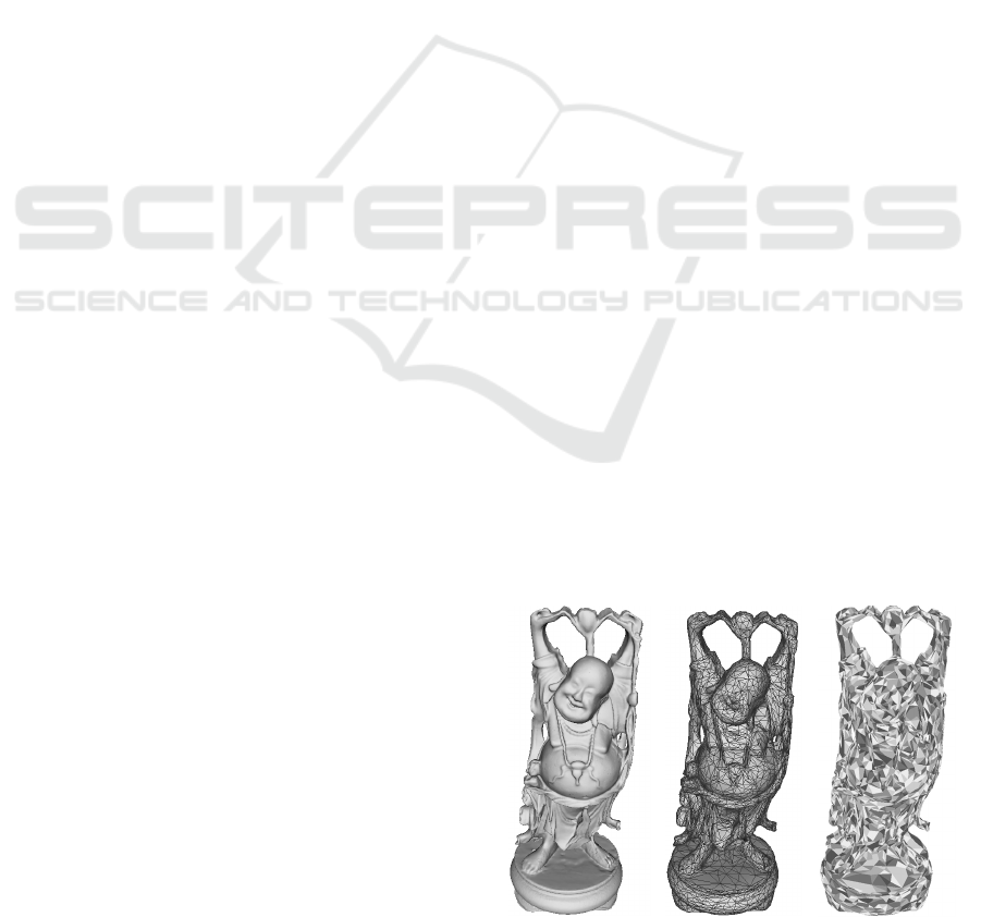
Figure 1: Happy_buddha model. a) The highest level of
detail: 543699 vertices and 31596 triangle strips. b) The
lowest level of detail: 5438 vertices. c) Strips at the lowest
level of detail.
In this paper, we present a continuous uniform
resolution model that efficiently manages algorithms
395
Ramos F., Gumbau J. and Chover M..
AN EFFICIENT APPROACH TO RENDER 3D MESHES BY MANAGING MULTIRESOLUTION TRIANGLE STRIPS.
DOI: 10.5220/0003943203950403
In Proceedings of the International Conference on Computer Graphics Theory and Applications (GRAPP-2012), pages 395-403
ISBN: 978-989-8565-02-0
Copyright
c
2012 SCITEPRESS (Science and Technology Publications, Lda.)
and data structures for real-time rendering of
multiresolution polygonal meshes. The model is
conceived in such a manner that mesh updating be
fast and efficient. Thus, some data structures are
ordered in accordance with the level of detail, it is
also possible to integrate part of these into the
graphics hardware, providing a hardware orientation
to the model. Moreover, the model has been
designed to facilitate the application of any hardware
and software acceleration technique: coherence,
vertex cache optimized stripification, OpenGL
extension, and so on.
The model has been implemented on
multiresolution meshes, initially generated by means
of vertex cache static stripification techniques
(NVIDIA, 2003) and based on progressive edge
collapses (Garland and Heckbert, 1997). Certain
data structures have also been implemented on the
graphics hardware (NVIDIA, 2002).
Main contributions of this model are:
Spatial cost. Simple data structures, oriented and
built for easy application of acceleration techniques
and for fast removal of degenerate triangles. This
provides improvements of approximately 25% in
this aspect.
Complete exploitation of coherence. At an
extraction level, we base level-of-detail extraction
on information that changes from one LOD to
another. At a visualization level, it uses efficient and
fast-access data structures. Extraction cost is
improved by approximately 40%.
Hardware integration: Allocation of the model
data structures into the graphics hardware and
complete exploitation of the most modern
techniques in hardware acceleration for current
GPUs. Thus, visualization speed improvement can
be as high as 5 times faster.
2 RELATED WORK
Garland (Garland, 1999) defines a multiresolution
model as a model representation that captures a wide
range of approximations of an object and which can
be used to reconstruct any one of them on demand.
Ribelles (Ribelles et al., 2002) presented a
characterization of multiresolution models. This
work classifies the models taking into account other
criteria. A classification obtained from the same
work separates continuous multiresolution models
into uniform and variable models.
Variable resolution models are able to
concurrently render two or more resolutions on the
same multiresolution mesh, although these models
consume a great deal of rendering time in level of
detail extraction. This is mainly due to the use (on
models based on triangle strips) of dynamic
stripification, which requires new rendering
primitive calculations in real-time, in addition to the
cost of maintaining various resolutions on the same
mesh. This type of model has advanced
considerably, and there are many solutions available:
(Hoppe, 1997); (El-Sana et al., 1999); (Stewart,
2001); (Shafae and Pajarola, 2003).
In general, continuous uniform resolution models
have lower extraction times and allow a total
rendering time that is more competitive than variable
resolution models. After the appearance of
progressive meshes, a model based on triangles and
implemented in the DirectX graphics library, some
models of this type were presented.
The first multiresolution model to use the
triangle fan primitive in their data structures, taking
advantage of the connectivity information between
triangles in a mesh, is the model by Ribelles et al.
called MOM-Fan (Ribelles et al., 2000). The main
drawback of this model is the high number of
degenerate triangles used in representation, although
they are purged before the rendering stage. Another
drawback of the model is that the average number of
triangles in each triangle fan is small. Furthermore,
rendering primitives are triangle lists, which have
lower performance than triangle strips.
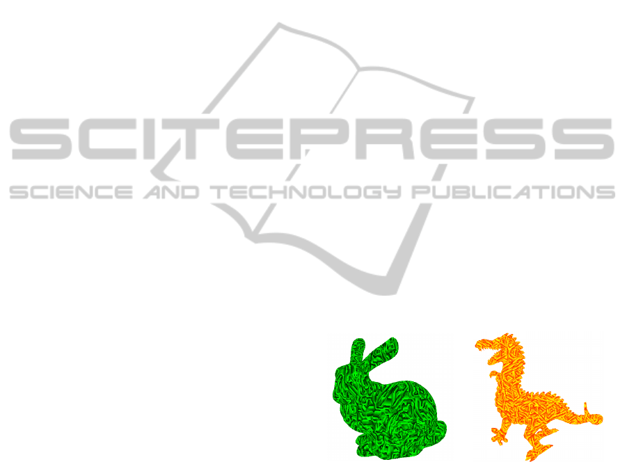
Vertices:34834
Strips: 6194
Vertices:54296
Strips: 58799
Figure 2: Some objects with triangle strips generated by
NvTriStrip utility.
As regards strips, the first multiresolution model
to take advantage of the triangle strip on the whole
model is that of Belmonte et al., called MTS
(Belmonte et al., 2003). Its main drawback is the
high spatial cost, and its level-of-detail extraction
time, although that loss is minimized by means of
rendering with triangle strips.
Recently, LodStrips (Ramos and Chover, 2004)
was presented, as an evolution of (Ramos et al.,
2004). This model is wholly based on triangle strips,
GRAPP 2012 - International Conference on Computer Graphics Theory and Applications
396
however it does not present simple data structures
either to implement or to integrate them into the
graphics hardware. Moreover, its spatial cost is
considerable.
In general, this kind of models, either offer such
a high level of detail extraction cost that they
compensate rendering by means of implicit
connectivity primitives, or have low extraction cost
but without efficiently using these primitives.
Furthermore, in certain cases, storage cost becomes
excessive. In some models, another point to take into
account is that of difficulties in applying existing
acceleration techniques.
Nowadays, varied acceleration techniques have
appeared, which integrated into a multiresolution
model would become key to improve its
performance. Basically, we can notice: stripification
techniques oriented to exploit vertex caches
(NVIDIA, 2003) and hardware acceleration
techniques by means of graphics library extensions
(NVIDIA, 2002).
There also are works that intend to exploit new
GPUs characteristics. Chow presented a method for
geometry compression (Chow, 1997), Hoppe
developed an algorithm for generating triangle strips
taking into account vertex cache (Hoppe, 1999) and
Bogomjakov and Gostman presented a method for
vertex cache optimization applied to progressive
meshes (Bogomjakov and Gostman, 17).
3 MODEL CONSTRUCTION
Our model is built from a polygonal mesh, usually
composed of triangles on which a sequence of
processes is applied in order to obtain a
multiresolution representation in the model data
structures.
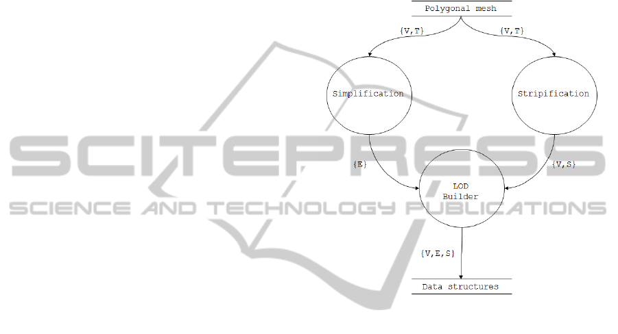
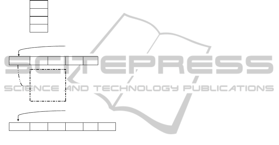
In figure 3, we can observe the data flow
diagram associated with the global construction
process.
3.1 Simplification
Simplification process allows us to obtain versions,
at different levels of detail, of the input polygonal
mesh. This algorithm is based on iterative
contractions of vertex pairs.
The fundamental information that supplies this
process consists of a sequence of collapses necessary
to simplify the polygonal mesh.
3.2 Stripification
The model is wholly based on triangle strip
primitives, which are generated at the highest level
of detail.
The stripification process consists of converting
a polygonal mesh, geometrically composed of
triangles, into triangle strips.
Figure 3: Model construction.
3.3 LOD Builder
Once obtained from the simplification process, the
information about vertices to be simplified for each
level of detail, and, from the stripification process,
triangle strips at the highest level of detail, we
proceed to the initial construction of the model.
In this process vertices are reordered in a
simplified way, that is, the first vertex to be
collapsed will be the zero; the second will be one,
and so on. Once completed, it is necessary to modify
the strips to reflect the changes realized. Finally, this
process stores the ordered vertices into the model
data structures and the triangle strips at the highest
level of detail. With this information, it is already
possible to build a multiresolution model that
traverses through the levels of detail. However,
whenever a change of level of detail occurs, it will
be required to search among the strips for the
vertices to be collapsed, and this operation has a
high cost in real-time. So, another process is
required that pre-computes and stores this
information into another data structure.
Moreover, this process computes, for each level
AN EFFICIENT APPROACH TO RENDER 3D MESHES BY MANAGING MULTIRESOLUTION TRIANGLE STRIPS
397
of detail, the strips that change and where exactly, in
every strip, the vertex to be simplified is located. It
permits to quickly traverse between levels of detail
of the model, offering optimum performance.
4 MULTIRESOLUTION MODEL
This model represents a mesh as a set of
multiresolution triangle strips (figure 4). It is an
evolution of models (Ramos and Chover, 2004)
(Ramos et al., 2004). Data structures were
noticeably improved, reducing their size and
integrating part of them into the graphics hardware.
Moreover, with these new data structures it is easy
to apply varied hardware acceleration techniques.
All this, results in lower level of detail extraction
times, lower visualization times and more efficient
storage cost compared to the recently published
uniform resolution multiresolution models.
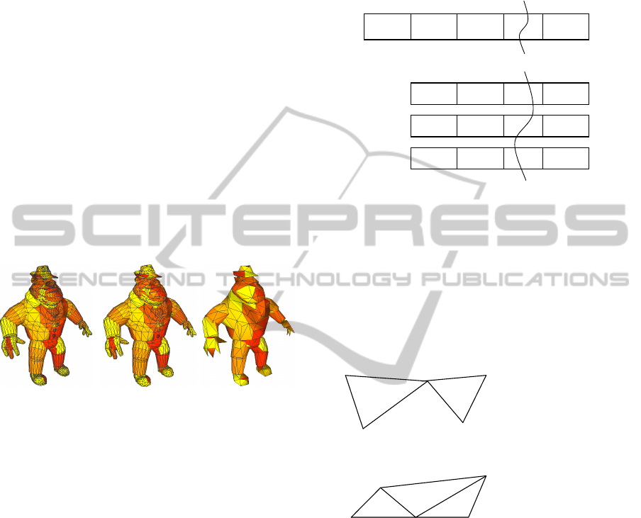
LOD 1 LOD 0.5 LOD 0
Figure 4: Three levels of detail from AL model.
At the beginning, data structures are informed by
the pre-process that constructs the model. All this
information is loaded at runtime and, afterwards,
depending on application parameters, collapses,
splits or resizes into multiresolution strips are
performed.
4.1 Basic Data Structures
In order to visualize a polygonal mesh at the highest
level of detail, we only need two data structures:
hStrips and hVertices. hVertices stores the 3D
coordinates for each vertex in the mesh, and hStrips,
a set of triangle strips, where each strip contains a
sequence of indices to hVertices. Figure 5 shows a
simple representation of those data structures.
After the construction process, we know where
collapses each vertex. This information is essential
for level of detail management because it will
determine collapses and splits onto the mesh,
obtaining the LOD demanded by the application.
All this information in managed by the
hVertexLOD data structure, storing for each LOD,
the index to the vertex to collapse when that LOD is
traversed.
Figure 5: hVertices and hStrips representation.
Thus, with these three data structures, we can
build a simple multiresolution model. However, this
initial idea has a problem: to move across levels of
detail is necessary to update strips looking for the
vertex to collapse in every one. This task would
imply a no competitive multiresolution model in
some aspects, overall, in level of detail extraction
cost.
Figure 6: Type of patterns removed by model data
structures.
A possible solution to this problem, above
mentioned, that improves very much the model
performance, consists of storing, in the data
structures, what strips change, and for each strip in
what position is located the vertex to be collapsed. It
allows us to quickly locate information to be
modified from a LOD to another. This approach
offers a good performance, but as model moves to
coarse LODs, an accumulation of identical vertices
is produced. Sending these vertex repetitions to the
graphics hardware does not contribute at all to the
final scene, because it is equivalent to send
degenerated triangles.
hVertices
012…n
x0,y0,z0 x1,y1,z1 x2,y2,z2 … xn,yn,zn
hStrips
01…
0
index00 index01 … index0a
1
index10 index11 … index1b
……………
p
indexp0 indexp1 … indexpr
5
5
6
6
2
2
3
3
4
4
Strip: 5 6 2 2 2 3 4
Replace aa(a)+ by aa
Strip: 5 6 2 2 3 4
5
5
6
6
2
2
3
3
4
4
Strip: 5 6 2 3 2 3 4
Replace ab(ab)+ by ab
Strip: 5 6 2 3 4
GRAPP 2012 - International Conference on Computer Graphics Theory and Applications
398
We have checked that most vertex repetitions,
which can be removed, follows patterns like aa(a)+
or ab(ab)+. Patterns aa(a)+ are replaced by aa, and
ab(ab)+ by ab. Figure 6 shows an example for each
kind of pattern, we can observe that final geometry
of strips do not change after removing these patterns.
Figure 7: Model data structures.
In summary, we need additional data structures
in order to support the aspects before mentioned: to
index vertex to be collapsed and to remove more
frequent patterns. These functions are performed by
hRecordsLOD and hInterLeavedData.
hRecordsLOD data structure is managed by
pCurrentRecordLOD, which is always positioned on
the first record of hRecordsLOD to be applied in the
next level of detail to the current one. Every record
of this data structure contains the minimum
information required to change a strip in a specific
LOD. Concretely:
Strip Strip to be modified
#Collapses Number of collapses
#ResizesL1 Number of aa(a)+ patterns to be
removed
#ResizesL2 Number of ab(ab)+ patterns to be
removed
In this record, strip field will determine over
what strip we are operating, and next fields let find
in hInterLeavedData the type of operation to
perform.
On the other hand, hInterLeavedData contains
this information:
Collapses
Positions in a strip where a vertex will be replaced by
another.
ResizesL1
Composed of position and number of aa(a)+ patterns in
this position.
ResizesL2
Composed of position and number of ab(ab)+ patterns
in this position.
In figure 7, we show a representation for every data
structure.
Construction Example. Model construction starts
from the information obtained from the
simplification and stripification processes. This
information is stored in hVertexLOD, which saves,
for each level of detail, what vertex collapses. In this
case (figure 8), and due to the model organization, in
LOD 0, vertex 0 is collapsed to 7, in LOD 1 vertex 1
to 2, and so on. From the stripification process we
obtain hStrip, which contains indices to vertices.
With this data, transition calculations sub process
starts. It pre-calculates the changes to be produced
into strips from the highest level of detail to the
lowest one.
In figure 8, we can observe the model
construction process saving information to the data
structures.
From the highest level of detail (LOD 0), we can
observe that to move to LOD 1, we must replace
vertex 0 by 7, in every strip where it appears. Once
collapses are performed, we proceed to detect vertex
repetition patterns. In this case, a pattern 4 7 is
detected in position 5. In brief, we have in strip 0,
one collapse and one pattern ab(ab)+, so [0,1,0,1].
Furthermore, the collapse is located in position 6,
and the pattern in position 5 and it repeats once, so
[6,5,1]. Thus, we are building the model until the
lowest level of detail.
4.2 Coherence
In this model, we have applied coherence at two
levels: coherence at an extraction level and
coherence at a visualization level.
Coherence at an extraction level means taking
advantage of information obtained from the last
level of detail extracted. Use of this kind of
coherence noticeably improves time consumed by
level of detail extraction algorithm, avoiding
extractions already computed. Thus, if we are
visualizing certain LOD, to move to the next or
previous LOD will only need a few operations over
strips. These operations will require a data structure,
hStrips, with constant time in insertions and
deletions, although access is penalized.
Coherence at a visualization level means using
auxiliary data structures that provide a fast access
hVertexLOD
LOD
Vertex
To
Collapse
0 index0
1 index1
……
q indexq
hRecordsLOD
pCurrentRecordLOD
Rec00 Rec01 Rec10 … RecQS
hInterleavedData
pCurrentData
Pos00 Pos01 L101 Pos02 L202 …
Strip
#Collapses
#ResizesL1
#ResizesL2
AN EFFICIENT APPROACH TO RENDER 3D MESHES BY MANAGING MULTIRESOLUTION TRIANGLE STRIPS
399
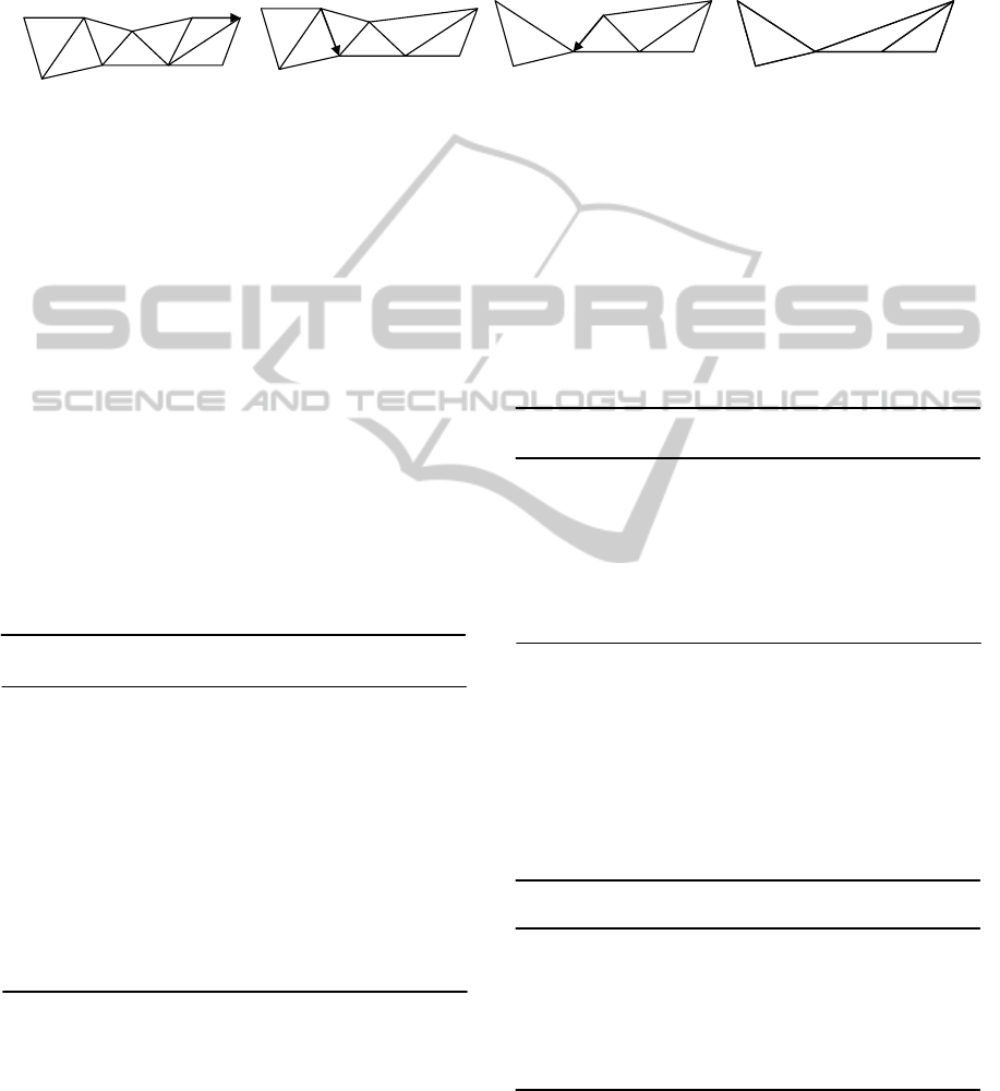
Figure 8: Model construction example.
and, thus, accelerates visualization. This kind of
coherence can be applied at a software level and at
hardware level. At a software level, the most
efficient solution consists of using a fast data
structure, in terms of sequential data access
containing strips to be visualized for each moment.
Thus, while a LOD is maintained during certain
time, meshes are rendered at the maximum possible
performance. Moreover, maintenance of these strips
can be directly realized on the graphics hardware by
means of specific buffers in its memory. It improves
visualization very much, as shown in the results
section.
Algorithm 1: Level of detail extraction from a LOD to a
coarse one.
for(lod=currentLOD;lod<demandedLOD;lod++) {
for(i=0;i<totalRecs[lod];i++) {
strip=pCurrentRecordLOD->Strip;
stripChanged[strip]=1; //for visualisation
//Collapses
for(n=0;n<pCurrentRecordLOD->Collapses;n++){
hStrips[strip,*pCurrentData]=hVertexLOD[lod];
pCurrenData++;
}//aa(a)+ Patterns
for(n=0;n<pCurrentRecordLOD->ResizesL1;n++){
hStrips[strip].Erase( *pCurrentData ,
*(pCurrentData+1) );
pCurrenData+=2;
}//ab(ab)+ Patterns
for(n=0;n<pCurrentRecordLOD->ResizesL2;n++){
hStrips[strip].Erase( *pCurrentData ,
*(pCurrentData+1) );
pCurrenData+=2;
}
}//End for i
} //End for lod
Visualization. To exploit coherence in visualization,
every multiresolution strip has two representations:
hStrips, a data structure with constant time in
insertions and deletions, which corresponds with
model geometry at the current LOD, and another
representation, efficient and fast in access, which
contains the same strips ready to render. This
representation can be allocated in main memory or
directly in the graphics hardware, which produces a
great acceleration, as shown in results section.
Depending on the type of coherence in visualization
applied, the algorithm is also different.
Algorithm 2: Visualization algorithm with coherence at a
software level.
//visStrips: strips visualisation data structure
for(s=0;s<hStrips.size();s++) {
//Update visStrips when proceed
if (stripChanged(i)) {
visStrips[i]=hStrips[i];
stripChanged[i]=0;
}
//Send strips to GPU
glBegin(GL_TRIANGLE_STRIP);
for(v=0;v<visStrips[i].size();v++)
glVertex(hVertices[visStrips[i][v]);
glEnd();
} //End for s
In the visualization algorithm shown above, we
apply coherence at a software level. It uses visStrips,
which stores strips ready to render guaranteeing an
optimum access time. stripChanged data structure is
informed by extraction algorithm, indicating what
strips have changed in transitions between levels of
detail, thus we know when to update visStrips data
structure.
Algorithm 3: Visualization algorithm with coherence at a
hardware level.
//visStrips: strips visualisation data structure
for(s=0;s<hStrips.size();s++) {
//Update hardware buffer when proceed
if (stripChanged(i)) {
glBufferSubDataARB(. . .);
stripChanged[i]=0;
}
//Send strips to the GPU using extensions
glDrawRangeElements(. . .);
} //End for s
Algorithm 3 corresponds to visualization at a
hardware level. This algorithm takes advantage of
new GPU capacities. It directly store and manage
strips to visualize from graphics hardware memory.
5
5
1
1
3
3
2
2
4
4
0
0
7
7
8
8
hVertexLOD:[7,3,3,4]
hStrip 0: 6 5 1 3 2 4 0 4 7 8
LOD: 0
6
6
5
5
3
3
2
2
4
4
7
7
8
8
hStrip 0: 6 5 1 3 2 4 0 4 7 8
Collapse 0 >> 7
hStrip 0: 6 5 1 3 2 4 7 4 7 8
Repet (v1 v2)+
hStrip 0: 6 5 1 3 2 4 7 8
LOD: 1
6
6
5
5
1
1
3
3
2
2
4
4
7
7
8
8
pRecordsLOD:
NULL
pInterLeavedData:
NULL
pRecordsLOD:
[0,1,0,1]
pInterLeavedData:
[6,5,1]
hStrip 0: 6 5 1 3 2 4 7 8
Collapse 1 >> 3
hStrip 0: 6 5 3 3 2 4 7 8
LOD: 2
pRecordsLOD:
[0,1,0,1]
[0,1,0,0]
pInterLeavedData:
[6,5,1,2]
hStrip 0: 6 5 3 3 2 4 7 8
Collapse 2 >> 3
hStrip 0: 6 5 3 3 3 4 7 8
Repet: (v1)+
hStrip 0: 6 5 3 3 4 7 8
LOD: 3
6
6
5
5
3
3
4
4
7
7
8
8
6
6
5
5
3
3
4
4
7
7
8
8
pRecordsLOD:
[0,1,0,1]
[0,1,0,0]
[0,1,1,0]
pInterLeavedData:
[6,5,1,2,4,3,1]
GRAPP 2012 - International Conference on Computer Graphics Theory and Applications
400
Different versions of this algorithm have been
developed, storing only vertices in GPU, vertices
and strips, and using two different OpenGL
extensions too. We have checked the improvements
achieved with this kind of visualization.
5 RESULTS
This model was submitted to several tests, all of
which were aimed at evaluating the rendering time
in a real-time application by applying different
acceleration techniques.
Tests designed to compare multiresolution
models follow the ones introduced by (Ribelles et
al., 1999) and those carried out in this study was the
linear test: this consists in extracting a number of
LODs of the model in a linear and proportionately
increasing or decreasing way.
To carry out the tests, some well-known meshes
from the Stanford 3D Scanning Repository were
taken as a reference, so as to make it easy to
compare this model with other well-developed
models.
Tests were carried out using a NVIDIA GeForce
graphics card. C++ was employed for the
implementation, using the graphics library OpenGL,
and it is completely portable.
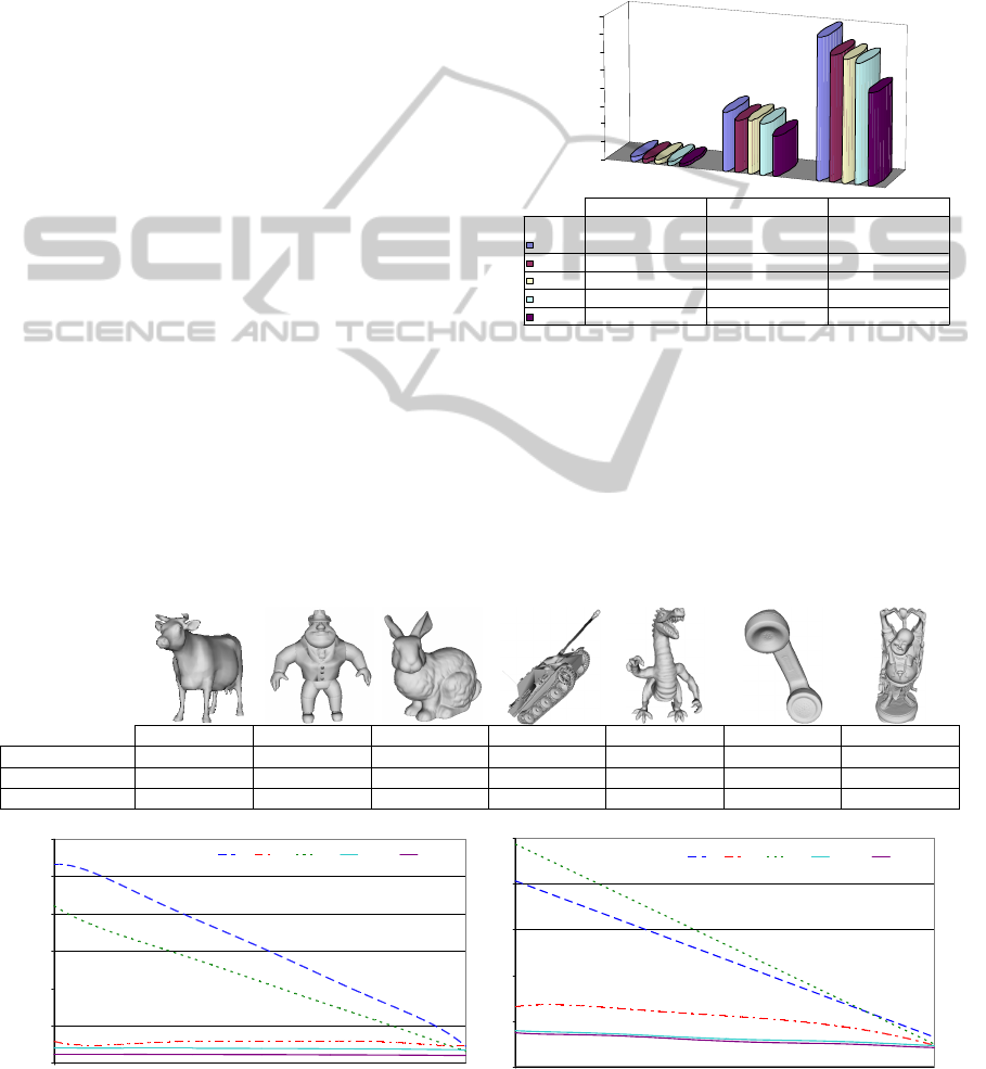
5.1 Spatial Cost
Figure 9 shows a spatial cost comparative between
the most important continuous uniform resolution
models, at present time. As we can see, the
presented model improves lodstrips, which had the
best spatial cost among existing models, in around a
40%.
Figure 9: Spatial cost comparison.
5.2 Level of Detail Extraction Cost
In figure 10a, we can observe that the presented
model, hStrips, offers the best extraction time from
compared models. It is mainly due to the effect of
using coherence in extraction algorithm and to the
efficient data structures implementation that manage
level of detail.
Cow AL Bunny Panther Dragon Phone Buddha
Vertices 2904 3618 34834 38911 54294 83044 543699
Strips 551 177 6194 4368 8799 1747 31596
Storage MB. 0.17 0.20 2.64 2.00 4.01 5.08 35.51
Figure 10: Extraction (a) and visualization (b) cost comparison for the bunny model with continuous uniform resolution
models.
0.00
1.00
2.00
3.00
4.00
5.00
6.00
7.00
8.00
MegaBytes
Vertices
2904 34834 83044
PM
0.27 3.28 7.86
MOM
0.24 2.88 6.94
MTS
0.25 2.96 6.77
LodStrips
0.22 2.83 6.64
hStrips
0.17 2.21 5.08
Cow Bunny Phone
Extraction times
0
2
4
6
8
10
12
1 0
Level of detail
Milliseconds
PM MTS MOM LodStrips hStrips
Visualization times
0
5
10
15
20
25
1 0
Level of detail
Milliseconds
PM MTS MOM LodStrips hStrips
AN EFFICIENT APPROACH TO RENDER 3D MESHES BY MANAGING MULTIRESOLUTION TRIANGLE STRIPS
401
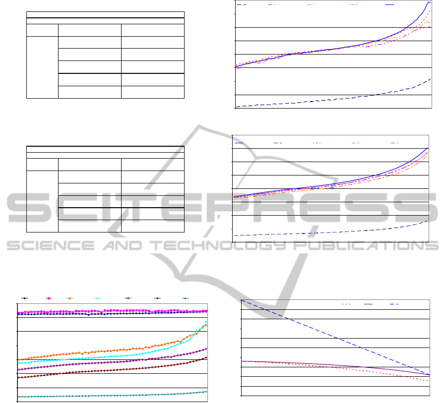
a) Bunny model frames per second average b) Bunny model performance chart
c) Buddha model frames per second average d) Buddha model performance chart
Figure 11: Bunny and Buddha model rendered by means of hardware acceleration techniques.
Figure 12: Multiresolution performance obtained from our
model, rendering with MultiDraw extension allocating
vertices and strips in the graphics hardware memory.
Figure 13: Vertices sent comparison for the phone model,
from the highest lod (1) to the lowest (0).
5.3 Visualization
Results of visualization are shown in figure 10b,
where it is compared to other models using
immediate mode to render. It is possible to observe
that our model offers the best visualization times. In
spite of rendering in immediate mode, the coherence
at a software level is exploited.
5.4 Hardware Acceleration
Rendering by means of hardware acceleration
techniques noticeably improves models
performance. On one side, we might upload different
kind of information to special buffers in the graphics
hardware memory. We have tested these buffers
uploading only vertex information and uploading
vertex and strips index information. It is shown at
figure 11 as (v) and (v+i) respectively. On the other
side, we can take advantage of those buffers by
using OpenGL extensions, like glDrawRangeEXT
and glMultiDrawsEXT. Thus, in figure 11, we can
see the effect of combining these modern features
offered by current GPUs, with a multiresolution
model that exploits them to the maximum.
Comparing immediate mode to VBO Multidraw
V
ertices 34834 Strips 6194
Bunny Model
380
382
VBO (v) DrawRange
Test Hardware technique
Linear Test
Immediate Mode
VBO (v) MultiDraw
VBO (v+i) MultiDraw
VBO (v+i) DrawRange
Render (fps)
187
371
372
Acceleration techniques performance
150
200
250
300
350
400
450
500
550
1 0
Level of detail
Frames per second
Immediate DrawRange (v) DrawRange (v+i) MultiDraw (v) MultiDraw (v+i)
V
ertices 543699 Strips 31596
VBO (v+i) MultiDraw
Buddha Model
Test Hardware technique Render (fps)
46
Linear Test
Immediate Mode 8
VBO (v) DrawRange 45
VBO (v+i) DrawRange 43
VBO (v) MultiDraw 44
Acceleration techniques performance
0
10
20
30
40
50
60
70
80
0 1
Level of detail
Frames per second
MultiDraw (v+i) Immediate MultiDraw (v) DrawRange (v+i) DrawRange (v)
Rendering using MultiDraw (v+i)
0
100
200
300
400
500
600
700
1 0
Level of Detail
Frames per Second
Cow AL Bunny Panther Dragon Phone Buddha
Level of detail
0
50000
100000
150000
200000
250000
300000
350000
400000
450000
500000
1
0
V
ertices sent
Vertices
MTS hStrips PM & MOM
GRAPP 2012 - International Conference on Computer Graphics Theory and Applications
402

(v+i) technique, improvements are considerable, on
average, around 200% for the bunny model and
570% for the budhha model.
Figure 11 shows a chart with various models
tested with the best performance technique:
MultiDraw (v+i).
5.5 Tripification Techniques
As shown in figure 13, hStrips model sends more
vertices to the GPU than MTS. When it moves to
coarser LODs, degenerated triangles appear, it does
not affect to visual mesh quality, but useless
information is processed. hStrips model removes
much of degenerated triangles, although some
remain. This is an aspect to be improved in future
work. Notwithstanding, hStrips is the best model in
visualization cost.
6 CONCLUSIONS
We have presented a uniform resolution model that
noticeably improves existing models, in terms of
storage and visualization cost. This model features:
optimized hardware primitives, coherence, vertex
cache exploitation, graphics hardware integration
and low spatial cost.
Comparisons to existing multiresolution model
implementations show improvements of
approximately 25% in storage space cost, 40% in
level-of-detail extraction cost and visualization as
much as 5 times better by applying hardware
acceleration techniques.
ACKNOWLEDGEMENTS
This work was supported by the Spanish Ministry of
Science and Technology (Project TIN2010-21089-
C03-03) and Feder Funds, Bancaixa (Project
P1.1B2010-08) and Generalitat Valenciana (Project
PROMETEO/2010/028).
REFERENCES
Ribelles, J., López, A., Belmonte, O., Remolar, I., Chover,
M., 2002. Multiresolution modeling of arbitrary
polygonal surfaces: a characterization. In Computers
& Graphics, ISBN/ISSN 0097-8493, vol. 26, num. 3,
pp. 449-462.
El-Sana, J., Azanli, E., Varshney, A., 1999. Skip strips:
maintaining triangle strips for view-dependent
rendering. In Proceedings of Visualization 99. p.131-
137.
Shafae, M., Pajarola, R., 2003. DStrips: Dynamic Triangle
Strips for Real-Time Mesh Simplification and
Rendering. In Proceedings Pacific Graphics
Conference.
Stewart, A., 2001. Tunneling for Triangle Strips in
Continuous Level-of-Detail Meshes. In Graphics
Interface, p. 91-100.
Belmonte, O., Remolar, I., Ribelles, J., Chover, M.,
Fernández, M., 2003. Efficient Use Connectivity In-
formation between Triangles in a Mesh for Real-Time
Rendering. In Future Generation Computer Systems,
Special issue on Computer Graphics and Geometric
Modeling.
Ramos, F., Chover, M., Belmonte, O., Rebollo, C. ,2004.
An approach to improve strip-based multiresolution
schemes. In proceedings of WSCG 2004, Vol. 12, N.
2, p. 349-354.
Hoppe, H., Progressive Meshes. 1996. In SIGGRAPH
1996, p. 99-108.
Ribelles, J., López, A., Belmonte, O., Remolar, I., Chover,
M., 2000. Multiresolution Modeling of Polygonal
Surface Meshes Using Triangle Fans. In Proceedings
of 9th DGCI 2000, 431-442.
Ramos, F., Chover, M., 2004. LodStrips: level of detail
strips. Lecture notes in Computer Science,
Proceedings of Computational Science ICCS 2004 vol.
3039, pp. 107-114.
NVIDIA Corporation. NvTriStrip Library, 2003. Available
in http://developer.nvidia.com/object/nvtristrip_
library.html.
Garland, M., Heckbert, P., 1997. Surface simplification
using quadric error metrics. In Proceedings of
SIGGRAPH ’97 p. 209-216.
NVIDIA Corporation, 2002. ARB_vertex_buffer_object
Specification. In http://oss.sgi.com/ projects/ ogl-
sample/ registry/ ARB/ vertex_buffer_object.txt
Garland, M., 1999. Multiresolution Modeling: Survey &
Future Opportunities. In Proceedings
EUROGRAPHICS’99, p. 111-131.
Hoppe H., 1997. View-dependent refinement of
progressive meshes. In Proceedings of SIGGRAPH
1997. p. 189-198.
Hoppe, H., 1999. Optimization of Mesh Locality for
Transparent Vertex Caching, In Proceedings of
SIGGRAPH 1999, p. 269-276.
Chow, M., 1997. Optimized Geometry Compression for
Real-time Rendering. In
Proceedings of the IEEE
Visualization 1997, p. 347–354.
Bogomjakov, A., Gostman, C., 2001. Universal Rendering
Sequences for Transparent Vertex Caching of
Progressive Meshes. In Proceedings of Graphics
Interface 2001.
Ribelles, J., Chover, M., Lopez, A., Huerta, J., 1999. A
First Step to Evaluate and Compare Multiresolution
Models, In Short Papers and Demos of
EUROGRAPHICS 1999, p. 230-232.
AN EFFICIENT APPROACH TO RENDER 3D MESHES BY MANAGING MULTIRESOLUTION TRIANGLE STRIPS
403
