
POWERTRAIN SLIDING MODE CONTROL IN SHEV FOR
IMPROVEMENT OF FUEL ECONOMY AND ESS LIFETIME
Xi Zhang and Chengliang Yin
National Engineering Lab for Automotive Control Electronics, Shanghai Jiao Tong University, Shanghai, China
Keywords: Sliding Mode Control, SHEV, Battery Lifetime Extension, Speed Control, Torque Control.
Abstract: This paper proposes a powertrain sliding mode control strategy for a series hybrid electric vehicle (SHEV)
aimed at improving fuel economy and energy storage system (ESS) lifetime. An ESS charging curve
considering positive factors for ESS lifetime extension is predetermined, and two robust sliding mode
controllers using the fixed boundary layer technology are designed. One is in charge of engine speed
control, and the other is for torque control. Thus the powertrain control system could not only reduce
emissions due to engine efficiency enhancement but extend ESS lifetime. Finally, simulation results using
ADVISOR confirm validity of the proposed strategy.
1 INTRODUCTION
Electric power as the only propulsion power for a
series hybrid electric vehicle (SHEV) comes from
the ESS and the engine/generator set that converts
the energy from fuel into electricity. In SHEV,
Engine optimal operation region could be located
properly due to the particular structure.
Recently, appropriate control of the SHEV
powertrain for emission reduction has been a
research hotspot. A modified instantaneous
equivalent consumption minimization strategy
(ECMS) into the SHEV powertrain control system
was introduced (Plsu and Rizzoni, 2005). Wang et
al., (2008) introduced a simulated annealing (SA)
algorithm to optimize the operational parameters for
SHEV fuel economy and emissions. Unfortunately,
these SHEV powertrain control strategies fail to
sufficiently address the highly nonlinear parameter
variations and sudden external disturbances during
the vehicle operation.
Sliding mode control (SMC) is very suitable for
automotive applications due to its low sensitivity to
disturbances and plant parameter variations
(Kachroo and Tornizuka, 1996; Utkin et al., 2009).
In this paper, powertrain controller design uses the
chattering-free fixed-boundary-layer technology for
chattering elimination. To locate the engine
operation in the optimal efficiency region, two
proposed sliding mode controllers responsible for
engine speed and torque respectively work together
due to the simultaneous speed and torque magnitude
constraints in such an area.
So far, few manufacturers concern the systematic
electrical solutions for battery lifetime extension
under the present battery technology. It’s available
to analyze some stress factors which induce ageing
and influence the rate of ageing (Svoboda, 2007).
Consequently, comparison between two ageing
processes with a couple of different stress factors
(e.g. SOC, charge rate, temperature, etc.) is possible
as long as other operating conditions are similar.
Some problems which affect battery lifetime
such as surge current, persistent high power, low
SOC and so on in conventional powertrain control
have to be concerned. To solve these, this paper
presents an ellipse-like-based battery charge
scenario. When the engine starts, the battery keeps
charging at a high rate from the low SOC level, and
its SOC increases fast. The charge current gradually
drops to zero when the SOC approaches to the
predetermined maximum level. The chaotic and fast-
variable current almost disappears, which is very
good for battery lifetime extension.
Finally, simulation results by modifying the
original SHEV model in Advanced Vehicle
Simulator (ADVISOR) confirm that the proposed
strategy is valid and efficient.
235
Zhang X. and Yin C..
POWERTRAIN SLIDING MODE CONTROL IN SHEV FOR IMPROVEMENT OF FUEL ECONOMY AND ESS LIFETIME.
DOI: 10.5220/0003945602350238
In Proceedings of the 1st International Conference on Smart Grids and Green IT Systems (SMARTGREENS-2012), pages 235-238
ISBN: 978-989-8565-09-9
Copyright
c
2012 SCITEPRESS (Science and Technology Publications, Lda.)
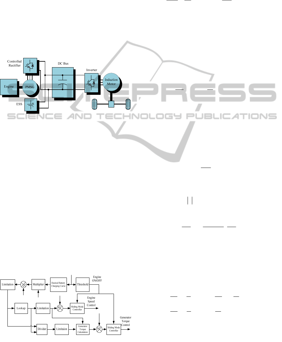
2 POWERTRAIN STRUCTURE
The structure of the studied SHEV powertrain is
shown in Figure 1. An internal combustion engine
(ICE) linked to a permanent magnet synchronous
generator (PMSG) provides main power in hybrid
mode. The ESS (battery pack) serves as the only
power source in the pure-electric-vehicle (EV) mode
and also absorbs the energy in the regeneration
process (braking or deceleration). In addition, the
battery pack will be charged by the engine when its
state of charge (SOC) drops to a predetermined
level, as determined by the control strategy.
Figure 1: Studied SHEV powertrain structure.
3 POWERTRAIN CONTROLLER
DESIGN
The block diagram of the proposed powertrain
control system is shown in Figure 2. Definitions of
variables in this figure are given as follows:
SOC
,
state of charge;
B
V
, battery output voltage;
r
B
I
,
calculated battery charging current;
L
P
, load demand;
r
B
P
, required power for battery charging;
ˆ
r
E
P
, engine
output power with limitations;
ˆ
r
E
ω
, calculated engine
speed;
*
E
ω
, calculated engine speed with limitations;
E
ω
, actual engine speed;
ˆ
r
E
T
, calculated engine
torque;
*
E
T
, calculated engine torque with limitations;
*
G
T
, final required generator torque; and
G
T
, actual
generator torque.
Figure 2: Proposed powertrain control system.
3.1 Engine Speed Control
The engine operation state function can be expressed
below
max
d
11
()
d
E
E
G
ss
uT T
tJ nJ
ω
ω
=−
(1)
where
max
()
E
T
ω
stands for the maximum torque at
speed
E
ω
,
1n
≈
denotes speed ratio between the
engine and generator,
s
J
is moment of inertia of the
engine/generator set, and
u
represents the engine
throttle angle (considered as the control variable)
and could be delineated as follows.
1
()
nn
uAu B
−
′
=−
(2)
where
1
G
s
A
T
nJ
=−
,
max
1
()
E
s
BT
J
ω
=−
, the subscript n
stands for the nominal value, and
u
′
is considered as
a new control variable.
Let the sliding surface
0
d
t
s
eet
λ
=+
∫
, where
*
E
E
e
ω
ω
=
−
and
λ
is a constant, and the new control
variable can be obtained using the fixed boundary
layer sliding mode control technology, expressed
below
*
d
ˆ
()
d
(( ) ) (( ),,)
E
eE
EE
ue
t
F
msat s
ω
θω λ
ω
ηαωφ
′
=
−+++
+
(3)
where
0
η
>
is a predetermined constant and
satisfies
s
ss
η
<−
;
0
φ
>
is the width of sliding
mode layer. The error function
()
eE
θ
ω
is given by
max
*
max
()
11
()
()
E
eE G Gn
sEs
T
TT
nJ T nJ
ω
θω
ω
=− + ⋅
(4)
3.2 Engine/Generator Torque Control
The state functions of the PMSG can be delineated
as follows:
(5)
where
d
i
and
q
i
, stator direct-axis and quadrature-
axis currents;
d
L
and
q
L
, stator direct-axis and
L
P
*
E
ω
r
E
P
r
E
P
ˆ
r
E
ω
ˆ
E
ω
r
E
T
ˆ
*
E
T
*
G
T
G
T
r
B
P
r
B
I
B
V
SOC
d
d
d
d
Gtrqq
qq
G
qGd m
dd
dGq
TKi
iu
R
ii
tL L L
iu
R
ii
tL L
ω
ωλ
ω
⎧
=
⎪
⎪
⎪
=
−− + −
⎨
⎪
⎪
=− + −
⎪
⎩
SMARTGREENS2012-1stInternationalConferenceonSmartGridsandGreenITSystems
236

quadrature-axis inductances;
m
λ
, flux of the
permanent magnet;
R
, stator winding resistance;
GE
ω
ω
≈
, generator speed (replaced by
E
ω
in the
following analysis);
trq
K
, torque constant;
d
u
and
q
u
, stator direct-axis and quadrature-axis voltages,
as control variables in the system.
Let the sliding surface
0
d, 1,2
t
iiii
se eti
λ
=+ =
∫
,
where
*
1 qq
eii=−
, and
*
2 dd
eii=−
. Similar to
derivation process in engine speed control, new
controls can be obtained as
(6)
and
(7)
where
0 ( 1,2)
i
i
η
>=
is a predetermined constant and
satisfies
(1,2)
ii i i
ss s i
η
<− =
, and
0 ( 1,2)
i
i
φ
>=
are
the widths of the two sliding mode layers.
Derivation of the error function is similar to that in
engine speed control.
Thus, the required stator direct-axis and
quadrature-axis voltages can be finally obtained to
guarantee desired generator torque.
3.3 Battery Charging Scenario Design
Although several options (e.g., parabola, ellipse,
line, trigonometric, etc.) exist for such a charging
scenario, only ellipse could satisfy all the fore-
mentioned requirements. In the meantime, the
ellipse curve is easy to calculate and easy to be
implemented in microprocessors. Consequently it is
possible to realize it in real time and real
applications. In this paper, a combination of line and
ellipse (see Figure 3) is eventually selected because
one wants the battery SOC to reach the “healthy”
low threshold SOC1 in the beginning phase (Phase
I) and then approaches to the maximum value
SOCmax in Phase II.
It has to be noted that the engine may not meet
the calculated power requirement that is the sum of
battery charging power and the peak driving power
demand at some instants. Thus constraints have to be
added.
When
the calculated engine power is located in
the high-efficiency region, the battery can be
charged along the pre-set curve. If the calculated
engine power exceeds the high-efficiency region, the
driving power demand is first satisfied while the
battery charging points may not lie on the pre-set
one. Whichever case happens, the dynamics of the
entire SHEV will not be influenced at all, the engine
always runs in the optimal region, and the
requirement of choosing a high-power engine could
also be avoided.
Figure 3: Desired battery charging curve.
4 SIMULATION RESULTS
This study employs ADVISOR for verification. The
original SHEV model is modified to embed the
proposed control system into the powertrain. In this
simulation, a Geo Metro 1.0L engine is selected. A
PMSG rated with 41kW-power and 95%-efficiency
is linked with the engine, and an induction motor
rated with 75kW-power and 95%-efficiency acts as a
traction motor. 100 Ovonic M70 cells compose the
battery pack where 50 are in series and 2 in parallel.
The inverter and controlled-rectifier both own the
structure of three IGBT/diode bridges.
The Orange County Cycle (OCC) is chosen as
the drive cycle for analysis. This is because the OCC
comprises of considerable acceleration/deceleration
processes and is capable of sufficiently validating
SHEV advantages on possible improvement of
system efficiency. The constants in the above
analysis are set as follows:
1
3540,
λ
=
2
650,
λ
=
1
2.03,
η
=
2
2.46,
η
=
min
0.6,SOC =
max
0.8,SOC =
1
0.68.SOC =
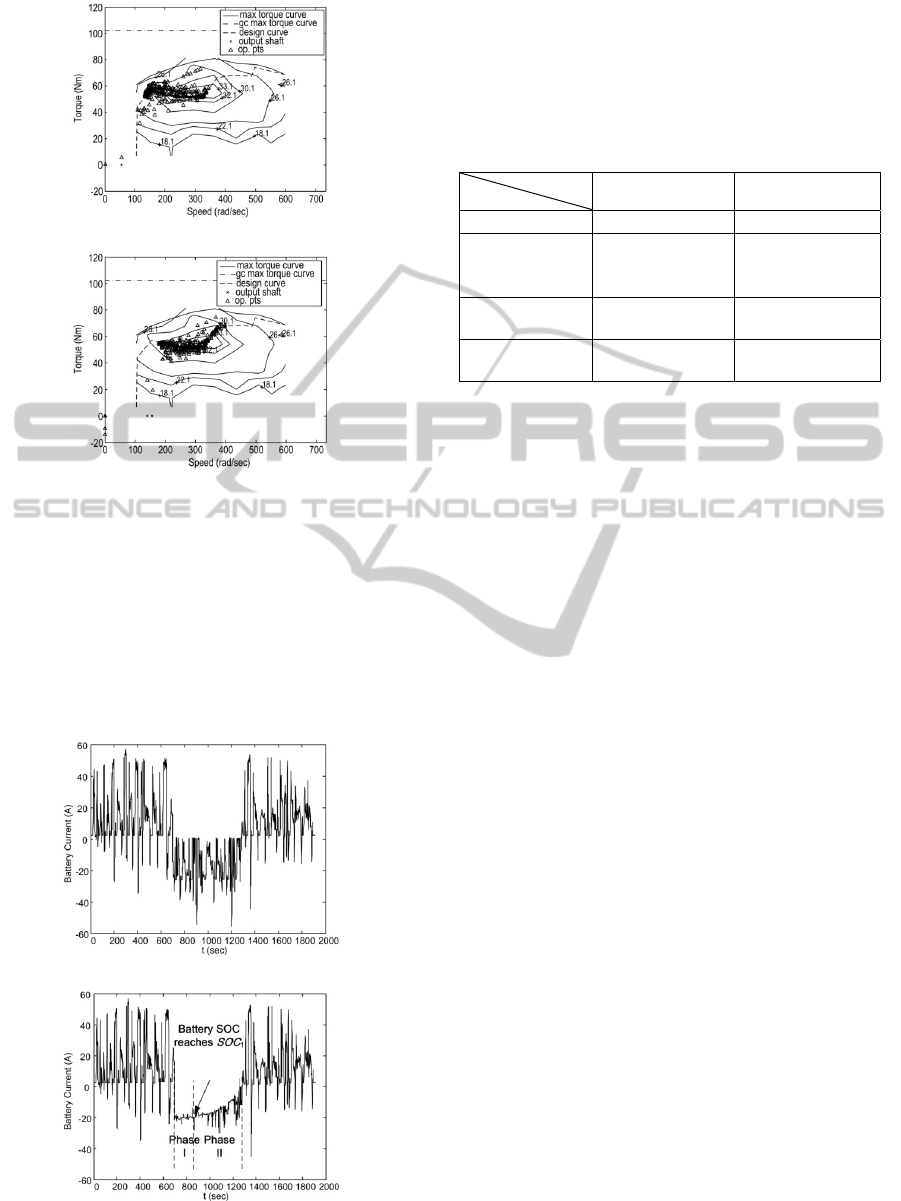
Figure 4 shows the engine operation efficiency
map. It is obvious from comparison between Figure
4(a) and 4(b) that most operation points using the
proposed strategy are located in the optimal region
while most points using the conventional method are
beyond such an area.
()
*
11 11
11 111
d
ˆ
()
d
( ) ( ( ), , )
q
e
i
uX e
t
FX msat X s
θλ
η
α
φ
=− + +
−+
()
*
22 22
22 222
d
ˆ
()
d
( ) ( ( ), , )
d
e
i
uX e
t
FX msat Xs
θλ
η
αφ
=− + +
−+
maxB
I
1
SOC
min
SOC
max
SOC
B
I
SOC
POWERTRAINSLIDINGMODECONTROLINSHEVFORIMPROVEMENTOFFUELECONOMYANDESS
LIFETIME
237
(a) Conventional method
(b) Proposed method
Figure 4: Engine operation efficiency map.
The battery current curves using the
conventional and proposed methods respectively are
depicted in Figures 5(a) and 5(b). It is clear that
chaotic and surge currents using the proposed
method in the normal (engine is ON) mode almost
disappeared compared to those using the
conventional method, which does good to the battery
lifetime extension.
(a) Conventional method
(b) Proposed method
Figure 5: Battery current during OCC.
Table 1 gives some index including MPG,
emissions, efficiency resulting from simulation
using two methods. It is obvious that the proposed
method performs better fuel economy, lower
emissions and higher efficiency.
Table 1: Performance comparison between two methods.
Method
Index
Conventional
Method
Proposed Method
MPG 37.8 40.9
Emissions
(g/mile)
HC:0.783,
CO:3.234,
NOx:0.838
HC:0.781,
CO:2.158,
NOx:0.820
Average Engine
Efficiency
0.301 0.322
Overall System
Efficiency
0.0720 0.0782
5 CONCLUSIONS
This study presents two sliding mode controllers for
SHEV powertrain on basis of a predetermined
optimal ESS charging scenario to improve fuel
economy and ESS lifetime. The engine speed and
torque could be located in the high-efficiency
region. Meanwhile the ESS lifetime extends due to
the designed charging curve avoiding negative
charging status, chaotic and surge currents, or
persistent high power. ADVISOR-based simulation
results validate the proposed powertrain control
system.
REFERENCES
Plsu, P., Rizzoni, G., 2005. A supervisory control strategy
for series hybrid electric vehicles with two energy
storage systems, In IEEE Vehicle Power and
Propulsion Conference.
Wang, Z., Huang, B., Xu, Y. et al., 2008. Optimization of
series hybrid electric vehicle operational parameters
by simulated annealing algorithm, In IEEE
International Conference on Control & Automation.
Kachroo P., Tornizuka, M., 1996. Chattering reduction
and error convergence in the sliding-mode control of a
class of nonlinear systems, IEEE Transactions on
Automatic Control.
Utkin, V. I., Guldner, J., Shi, J., 2009. Sliding mode
control in electro-mechanical systems, CRC Press.
Boca Raton.
Svoboda, V., Wenzl, H., Kaiser, R. et al., 2007. Operating
conditions of batteries in off-grid renewable energy
systems, Solar Energy.
SMARTGREENS2012-1stInternationalConferenceonSmartGridsandGreenITSystems
238
