PROCESS CONTROL SYNTHESIS IMPROVED BY STRUCTURAL
MODEL PROPERTIES
Hans-Christian Lapp and Hans-Michael Hanisch
Martin Luther University of Halle-Wittenberg, Halle, Germany
Keywords:
Discrete Event Systems, Process Control Synthesis, Net Condition/Event Systems, Invariants.
Abstract:
This contribution presents a novel approach to synthesize discrete process control on shop-floor level. It takes
advantage of the modular composition of the used modeling formalism. The synthesis procedure grounds
on the model of the uncontrolled plant behavior, as well as on specifications of forbidden states and desired
process behavior. Thus, the presented approach also opens the door to more flexibility, compared to solely
forbidden state specifications. The plant model structure is abstracted without loss of information into a
novel representation called Transition Invariants Graph. This representation is utilized to extract admissible
trajectories out of the reachable state space of the uncontrolled plant. Hence, the introduced approach reduces
the complexity during control synthesis procedure significantly by limiting the reachability analysis. That
makes it feasible to be used even in real-scale industrial systems.
1 INTRODUCTION
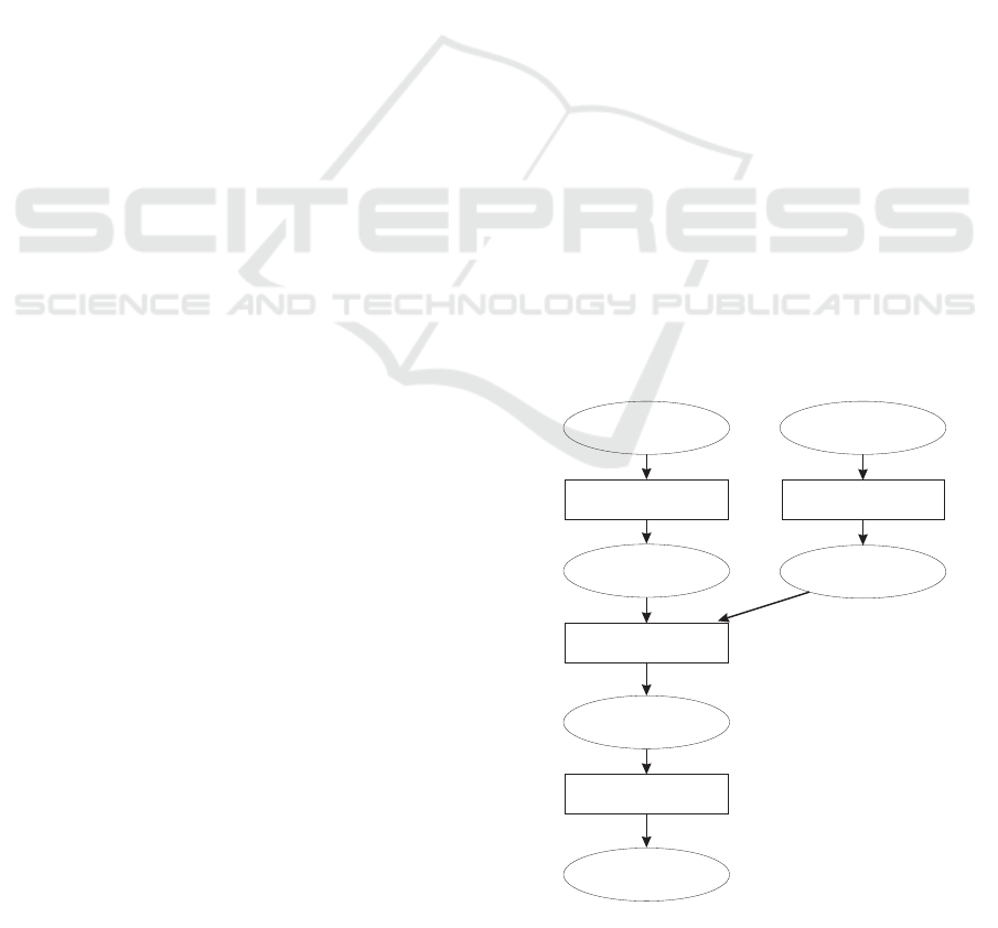
The purpose of formal control synthesis is to automa-
tically generate a controller model, which is proven to
be correct. Thus, it reduces the possibility of human
errors and eases the design process. Figure 1 shows
the scheme of the control synthesis procedure.
Control synthesis grounds on a model of the un-
controlled plant behavior and a specification of de-
sired or undesired behavior, mostly given in terms of
plant states (e.g. forbidden states for safety reasons).
Generally, complexity of control synthesis is a
crucial factor depending on the size of the plant
model. So, much research work has been done to han-
dle the costs and effectiveness of the synthesis pro-
cedure. Therefore, many of the existing approaches
aim on synthesizing on process control level, assum-
ing that there are underlying controllers on shop-floor
level which perform the control tasks of single com-
ponents.
The approach of Feng et al. (Feng et al., 2009)
takes into account the modular component-based
product-structure of manufacturing systems to derive
a hierarchy of decentralized supervisors and coordi-
nators.
Uzam and Wonham (Uzam and Wonham, 2006)
introduced a hybrid approach. They coupled Ra-
madge and Wohnham supervisors (automata) to DES
modeled with Petri nets (PN), to close the gap be-
plant
modeling
NCES-
plant model
distributed synthesis
model of
controllers (distributed)
code generation
Basic Function Blocks
based on IEC 61499
target behavior
formalisation
formal specification
Figure 1: Scheme of the control synthesis procedure.
tween and to benefit from the advantages of both for-
malisms.
A survey over PN based approaches is given, e.g.
by Holloway et. al (Holloway et al., 1997).
Li and Zhou (Li and Zhou, 2006) determine
liveness-enforcing supervisors based on PN structural
343
Lapp H. and Hanisch H..
PROCESS CONTROL SYNTHESIS IMPROVED BY STRUCTURAL MODEL PROPERTIES.
DOI: 10.5220/0003945703430351
In Proceedings of the 2nd International Conference on Pervasive Embedded Computing and Communication Systems (PECCS-2012), pages 343-351
ISBN: 978-989-8565-00-6
Copyright
c
2012 SCITEPRESS (Science and Technology Publications, Lda.)
properties called siphons and mixed integer program-
ming.
Iordache and Antsaklis gave a survey (Iordache
and Antsaklis, 2006) over Supervision based on Place
Invariants (SBPI). There, also structrual properties of
PN, namely place invariants, are used to generate a
supervisor.
Another structure-based approach was introduced
by Missal and Hanisch, (Missal and Hanisch, 2008a)
and (Missal and Hanisch, 2008b). They analyze the
pre-regions of forbidden states in plant model’s state
space, to synthesize distributed control. This work
takes advantage of a modular modelling formalism,
the so-called Net Condition/Event Systems (NCES),
which have extensions of PN as building blocks.
To reduce complexity during supervisor synthesis,
different techniques are used, amongst others, model
reduction (Uzam and Wonham, 2006), model abstrac-
tion (Feng et al., 2009) or utilization of model struc-
ture properties and mathematical model representa-
tion (Iordache and Antsaklis, 2006).
The approach presented in this contribution is
about synthesizing distributed controllers on shop-
floor level. It extends commonly used specifications
in terms of states by specifications of desired recur-
ring process behavior. A lossless abstraction of the
plant model structure is generated. This so-called
Transition Invariants Graph (TIG) is utilized to ex-
tract admissible (in the sense of the specification)
causal dependencies from the plant model. Based on
both kinds of specifications and the extracted causal
dependencies, an admissible subspace of the whole
reachable state space is computed. The boundaries
of this subspace are the starting points for determin-
ing a controller model. Hence, the controller model
is determined for meaningful behavior regarding the
specifications. The reduction of complexity is in the
partial computation of the state space, which is there-
fore called partial reachability analysis.
This contribution is structured as follows. Section
2 introduces the used modular modeling formalism.
The steps of the process control synthesis procedure
are presented in Section 3. An example is presented
in Section 4, followed by the conclusions.
2 MODELING
For DES and specification modeling,
S
NCES are used,
a 1-bounded (and therefore called safe) subclass of
Net Condition/Event Systems, which were introduced
in (Hanisch and Rausch, 1995). The crucial advan-
tage of
S
NCES is the modular model structure. Rec-
ommendations for a well-formed modular plant mod-
NameofModule
p51
p52
t62
t63
t64
t65
p50
eventarc
initialmarking
conditionarc
inhibitor arc
conditioninput
conditionouput
eventouput
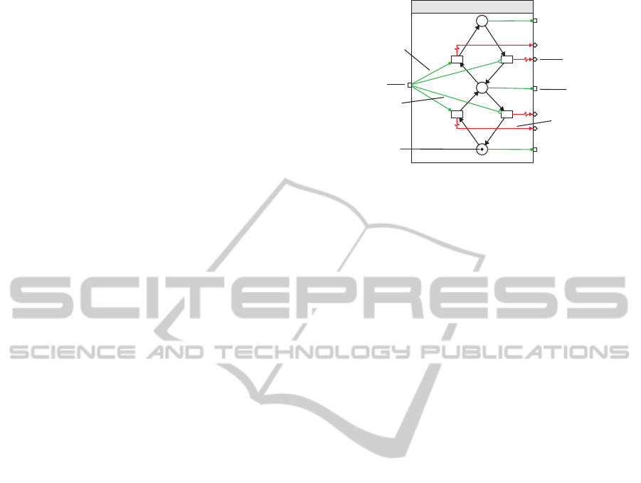
Figure 2: Example of a safe Net Condition/Event System ba-
sic module.
eling with
S
NCES are given in (Missal and Hanisch,
2008a).
S
NCES allow to model the behavior of
plant components encapsulated in reusable modules.
Modules are interconnected via signal arcs. Thus,
S
NCES offer a natural way to model even large-scale
systems, regarding their composition of basic compo-
nents and groups of components.
2.1 The
S
NCES Model
Two kinds of modules are defined within
S
NCES. The
first kind are basic modules. They are supposed for
modeling basic plant components (e.g. cylinders, sen-
sors, etc). The second kind are composite modules,
which are composed of basic modules and/or other
composite modules. Figure 2 shows a basic module,
which is also part of the example in Section 4. It rep-
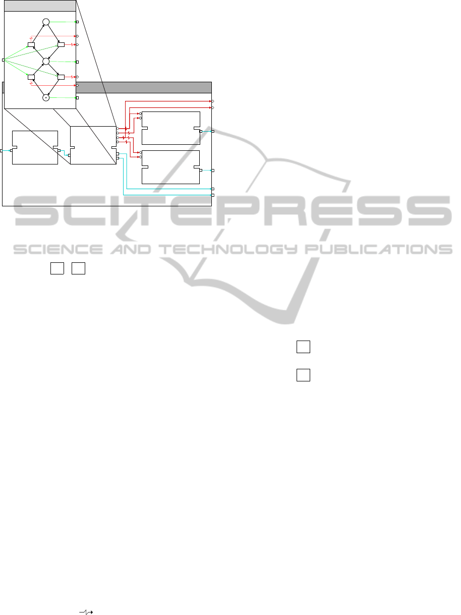
resents the behavior of a cylinder. Figure 3 shows ex-
emplarily a composite module, which is composed of
basic modules. Amongst others, it contains the basic
module depicted in Figure 2. The composite module
represents the component group for a cylinder, con-
sisting of the basic plant components actuator, cylin-
der and end positions sensors.
For more formal details about
S
NCES see
(Hanisch and Rausch, 1995), (Pinzon et al., 2004) and
(Missal and Hanisch, 2008a). Some fundamental def-
initions are given in the following.
Definition 1. A basic module M
B
is a tuple:
S
NCEM = {P,T, F,CN,EN,C
in
,
E
in
,C
out
,E
out
,CI
arc
,EI
arc
,CO
arc
,EO
arc
,em,m
0
}
where: P, T, F are (common to PN) sets of places,
transitions and ordinary arcs,
CN ⊆ P × T , EN ⊆ T × T
are the sets of condition and event signals,
C
in
, E
in
, E
out
, C
out
are the sets of signal in-/outputs,
CI
arc
⊆ C
in
× T , EI
arc
⊆ E
in
× T
are the sets of condition and event input arcs,
PECCS 2012 - International Conference on Pervasive and Embedded Computing and Communication Systems
344
Composite Module
Cylinder
p50
p51
p52
t62
t63
t64 t65
Actuator
Cylinder
Sensor
extended
Sensor
retracted
Figure 3: Examples of basic and composite modules.
CO
arc
⊆ P ×C
out
, EO
arc
⊆ T × E
out
are the sets of condition and event output arcs,
em : T → { ∧ , ∨ } is the event mode for every
transition,
m
0
is the initial marking of the places.
The defined PN and signal components are ar-
ranged in a modular structure, exemplarily shown in
Figures 2 and 3.
Definition 2. A composite module M
C
consists of
submodules, which can be also composite modules
or/and basic modules (Figure 3). The submodules of
M
C
are interconnected and connected with the inputs
and outputs of M
C
via signal arcs.
Definition 3. If an
S
NCE Module has no inputs or
outputs it is called safe Net Condition/Event Sys-
tem M
S
.
An input state is defined for the signal inputs of
S
NCE Modules as follows:
Definition 4. The input state is of an
S
NCEM is a
mapping is : C
in
∪ E
in
→ {0,1} assigning a value of
{0,1} to each signal input.
The semantics of
S
NCES are given in terms of
steps.
Steps are sets of transitions interconnected via event
signals. An event signal synchronizes two transitions
in one direction (t
i
t
j
) under the enabling condi-
tions.
To enable a transition or a step, only the marking
of places and the input state of a module are of inter-
est.
Definition 5. A transition t ∈ T of an
S
NCEM is:
1. marking-enabled at a marking m iff
(∀p ∈ P with (p,t) ∈ F : m(p) = 1) ∧ (∀p ∈
P with (t, p) ∈ F : m(p) = 0)
2. condition-enabled at a marking m and an input
state is iff
∀p ∈ P with (p,t) ∈ CN : m(p) = 1 and
∀c
in
∈ C
in
with (c
in
,t) ∈ CI
arc
: is(c
in
) = 1.
A transition is marking-enabled if all pre-places
are marked and all post-places are unmarked. A tran-
sition is condition-enabled if all places that are con-
nected via condition arcs are marked and all con-
nected condition inputs have the value one.
With these terms, we can define sets of event-
interconnected transitions that are called steps in gen-
eral and enabled steps in particular.
Definition 6. Let M be an
S
NCEM with the marking
m, the input state is and ξ ⊂ T a non-empty set of
transitions within M .
ξ is a step iff
1. |ξ ∩ (T
E
)| = 1,
while T
E
:= {t ∈ T |@t
0
∈ T : (t
0
,t) ∈ EN} and
2. for every transition t ∈ ξ with t /∈ (T
E
) holds:
• em(t) = ∨ ∧ ((∃t
0
∈ ξ : (t
0
,t) ∈ EN)∨ (∃e
in
∈
E
in
with (e
in
,t) ∈ EI
arc
: is(e
in
) = 1)) or
• em(t) =
∧ ∧ ((∀t
0
with (t
0
,t) ∈ EN : t
0
∈ ξ)∧
(∀e
in
∈ E
in
with (e
in
,t) ∈ EI
arc
: is(e
in
) = 1))
and
3. all transitions are free of conflicts to each other.
Ξ is the set of steps within M .
ξ is called enabled step under m and is iff ξ is
marking and condition-enabled under m and is and
there is no set of transitions with ξ
0
= ξ∪{t}, which is
also a step and marking and condition-enabled under
m and is.
The defined enabled steps are always maximal
steps and contain exactly one trigger transition. Con-
flict transitions must not be part of the same step.
The effect of firing an enabled step on the marking
of the net is defined as follows.
Definition 7. Let M be an
S
NCEM with the marking
m and the input state is.
If ξ is an enabled step under m and is, than ξ is en-
abled to fire. The successor marking m
0
is determined
for p ∈ M to:
PROCESS CONTROL SYNTHESIS IMPROVED BY STRUCTURAL MODEL PROPERTIES
345
m
0
(p) =
1 i f ∃t ∈ ξ : (t, p) ∈ F
0 i f ∃t ∈ ξ : (p,t) ∈ F
m(p) else.
An enabled transition is forced to fire by an in-
coming event signal.
2.2 The Specification Model
Next to the formal plant model, two kinds of for-
mal specifications are used in the presented approach.
The first kind are forbidden states, which are de-
fined in terms of state predicates (Missal and Hanisch,
2006). In (Missal and Hanisch, 2006) and (Missal
and Hanisch, 2008a), they are the starting points for a
backward search for controllable steps. This previous
work is integrated in the approach presented in this
contribution.
Definition 8. Let N be an
S
NCES, p ∈ P a place of N
and m a marking of N. A state atom ZA of N at m and
p is a declaration:
ZA = [m(p) = a]; a ∈ {0; 1}.
A state predicate ZP of N on m is a function of
state atoms:
ZP = ZA
1
∧ ZA
2
∧ ··· ∧ ZA
n
.
A state attribute ZE of N on m is a function of state
predicates:
ZE = ZP
1
∨ ZP
2
∨ ··· ∨ ZP
n
.
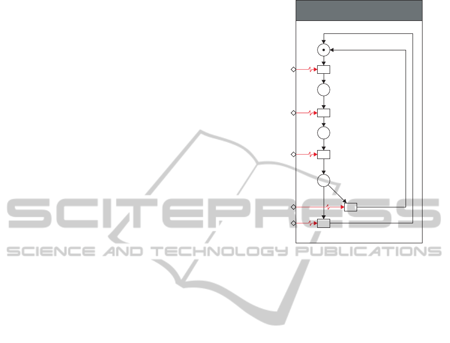
The second kind are formal specifications of the
plant’s desired process behavior, or more precisely,
the desired transformation of work piece (WP) prop-
erties during a process cycle. Work piece proper-
ties can be geometric properties or work piece posi-
tions, etc. These specifications are given in terms of
S
NCES as partial orders over the desired process be-
havior. Figure 4 shows an example cutout of such a
specification module. It reflects in general a partial
order over the work piece presence at different plant
locations (positions 1.. .4). This exemplary order is
partial because it only contains the work piece posi-
tions. The plant components at each position as well
as their activation sequences, which are necessary for
work piece processing are not included.
These modules are connected with event arcs to
the model of the uncontrolled plant behavior. For ex-
ample, the lower left event input WP to next station in
the module in Figure 4 is intended to receive an event
from a corresponding plant component, which signals
the transfer of a work piece to the next plant station.
The modularity of
S
NCES supports the supposed
distributed control synthesis in such a way, that spec-
ification modules can be assigned to each relevant
WP transfertoposition2
t88
WP transfertoposition3
t89
WP_holetransfertoposition4
t90
newWP arrivingatposition1
t91
WP reprocessing
t92
WP atposition1
p70
WP atposition2
p71
WP atposition3
p72
WP atposition4
p73
SpecificationModule
WP fromposition1
WP fromposition2
WP fromposition3
WP reprocessing
WP tonextstation
Figure 4: Simple example for a specification module speci-
fying work piece positions.
plant component or assembly group. This mapping
is used during the supposed distribution of the syn-
thesized control. Currently, the
S
NCES specification
modules are derived manually. But this step can be
automated if an unambiguous name assignment from
a design framework, e.g. a SysML-based specifica-
tion (Hirsch, 2010), to the
S
NCES model and specifi-
cation modules is guaranteed.
3 PROCESS CONTROL
SYNTHESIS
The basis for process control synthesis are formal
models of the uncontrolled plant behavior and a for-
mal specification, both modeled in
S
NCES and in-
terconnected via event arcs. When determining the
control model, the computation of the whole reach-
able state space of the plant model is avoided. In-
stead, specification-compliant paths are identified in
a new abstracted representation of structural prop-
erties of the plant model. These paths are used to
limit the reachability analysis to the specified behav-
ior. Thus, we do some kind of partial reachability
analysis to determine specification-compliant trajec-
tories through the state space of the plant model. Af-
terwards, the control model is distributed regarding
the plant model architecture.
The formal process control synthesis follows four
PECCS 2012 - International Conference on Pervasive and Embedded Computing and Communication Systems
346
steps:
1. Create superset of feasible paths (in model struc-
ture abstraction),
2. partial reachability analysis, based on specifica-
tions and previously determined path set,
3. determine controllable trajectories,
4. distribution and code generation.
These steps are described in detail in the following
subsections.
3.1 Create Superset of Feasible Paths
The specified process is cyclic. Thus, one can assume
that every relevant plant component will return into
its initial state. This fact is reflected in t-invariants of
the PN parts of the
S
NCES model. Therefore, every
single t-invariant of the plant model can be consid-
ered as “specification-compliant” in that sense, that it
does not contradict to a cyclic process behavior. T-
invariants are a well known property of PN (Starke
and Roch, 2002). In the following this property will
be extended by the signal interconnections of
S
NCES.
Thus, it is possible to determine an abstract represen-
tation of causal dependencies within the uncontrolled
plant model. This representation is called Transition
Invariants Graph (TIG) (Winkler et al., 2011).
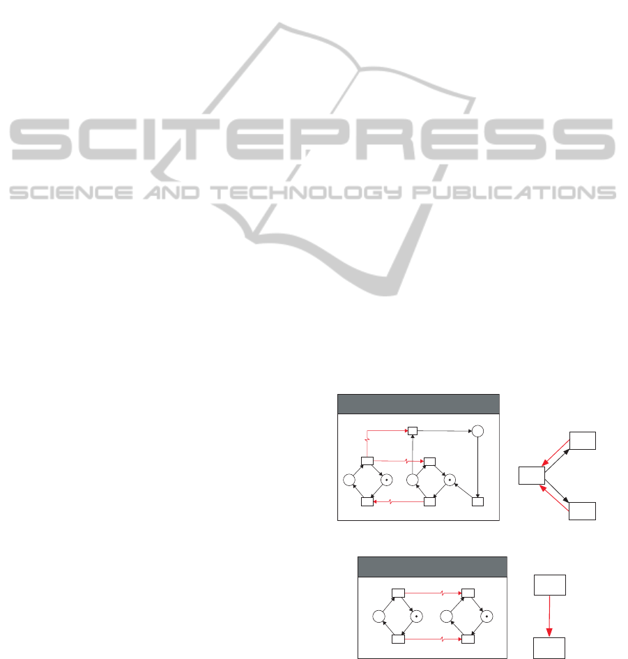
Examples for the transformation of
S
NCE Mod-
ules into TIG representation are given in Figure 5. In
detail, Figure 5(a) shows the transformation of nested
t-invariants. There, one event arc (t
2
, t
1
) is trans-
formed into two arcs in TIG because t
2
is part of two
nested t-invariants.
Figure 5(b) depicts the transformation of event-
synchronized places into TIG representation. Con-
trary to the foregone example, the two shown event
arcs are transformed into one arc in the TIG, be-
cause the two event arcs are rectified and got identical
source and sink t-invariants.
For example, the causal dependencies of an un-
controlled behavior model of a rotary table allow it to
rotate from one table position to the next. The causal
dependencies representing this behavior would be re-
flected in the TIG. In the sense of the process behavior
specification, this would be only a part of the desired
behavior. Thus, an admissible path within the TIG, in
the sense of the process behavior specification, con-
tains the causal dependencies which are reflecting the
whole desired process behavior. In the case of the ro-
tary table this might be a complete rotation passing all
table positions.
Thus, after determining the TIG, a set of admis-
sible paths within the TIG is determined. This path
set contains causal dependencies representing the de-
sired process behavior. This extraction of TIG paths
grounds on the given specification of desired process
behavior. Remember, this specification is given in
terms of
S
NCES and is connected via event arcs to
the plant model. Causal dependencies of interest as
well as their order can be determined by analyzing
the interconnections of process behavior specification
and plant model. These interconnections are also re-
flected in the TIG. Hence, they are utilized to extract
TIG paths which are complying with the given speci-
fication. That means:
• All causal dependencies of interest are included in
the extracted paths,
• and they are included in the specified order.
This set of extracted TIG paths is the superset of
feasible paths. During the following step, this set is
used to limit computational complexity when analyz-
ing the state space of the uncontrolled plant model.
3.2 Partial Reachability Analysis
The purpose of this step is to create a set of
specification-fulfilling trajectories through the state
space of the plant model, which realizes the desired
plant behavior. Dependent on the model of the uncon-
trolled plant behavior, the state space could be very
large and strongly interconnected. Thus, the specifi-
cations of forbidden states and desired process behav-
ior are used to restrict the state space computation to
an admissible specification-compliant subspace. That
t1 t2
t3
t4
t12
t13
p1 p2p3p4
p12
sNCES
2
t4,t12
1
3
t2,t1
2
t4,t3
t2,t1
(a) Transformation of nested t-invariants.
t1
t2
t3
t4
p1 p2 p3p4
sNCES
2
2
t1,t3 t4,t2
2
1
(b) Transformation of event-synchronized
places (Missal and Hanisch, 2009).
Figure 5: Examples for transforming
S
NCES into TIG.
PROCESS CONTROL SYNTHESIS IMPROVED BY STRUCTURAL MODEL PROPERTIES
347
is why this step is called partial reachability analysis
(pRA).
In the previous section, the process behavior
specification was used to determine a set of fea-
sible TIG paths representing some kind of desired
causal dependencies. Because every t-invariant con-
tains a set of transitions, the transitions along the
specification-compliant paths, which were extracted
in the previous step, can be determined easily. Fur-
thermore, the specification of forbidden states rep-
resents a set of partial markings, which must not be
reached.
Thus, the outcome of these two kinds of spec-
ifications are criteria to restrict the computation of
the reachable state space of the uncontrolled plant
model. Therefore, the resulting partial state space is
much smaller than the whole reachable state space.
Hence, subsequent analysis steps are eased, especially
regarding large-scale models of real industrial size.
The execution of the pRA is similar to the com-
monly known reachability analysis. Starting at an ini-
tial marking, every reachable step is calculated, ac-
cording to the possible state transitions given by the
current enabled step ξ. The pRA does not examine
state transitions, if:
1. They lead into a forbidden state, according to the
forbidden states specification.
2. They lead into a state, which implies an enabled
step ξ which does not contain at least one tran-
sition which is also contained in a specification-
compliant TIG path.
The rejected state transitions, which contradict to
the specifications, mark the boundaries of the state
space of the desired plant behavior. This boundaries
are the starting points for determining a control model
in the following step (Section 3.3).
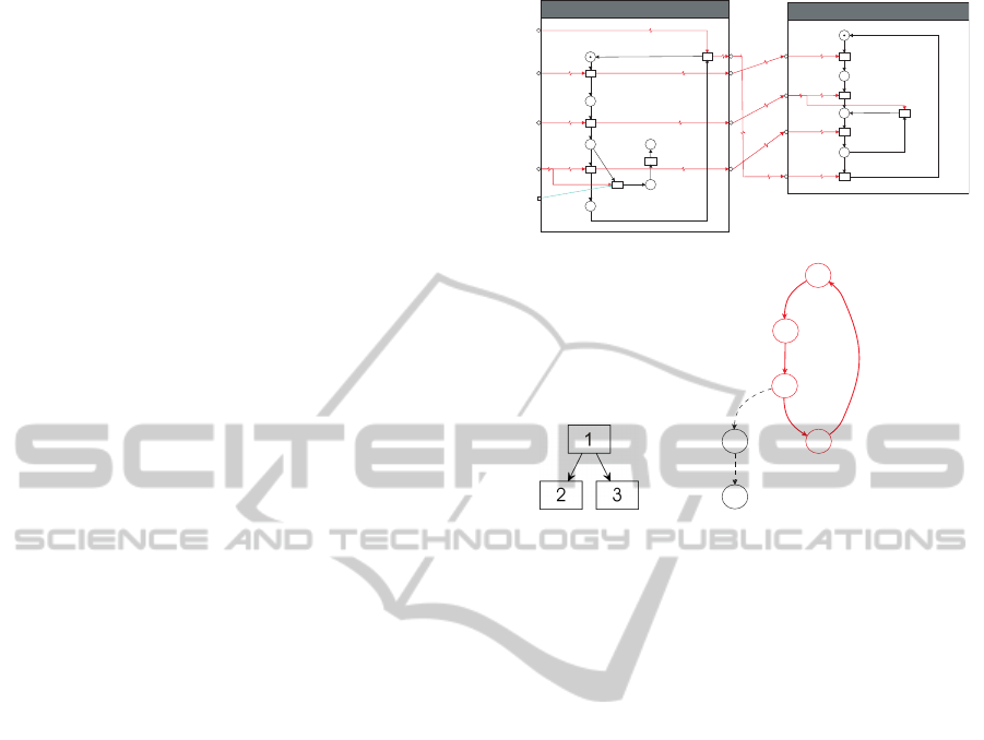
The following little example, depicted in Figure
6, should illustrate the intention of the pRA. The
left module in Figure 6(a) represents the model of
an uncontrolled plant behavior. The module on the
right is the corresponding specification of the cyclic
process behavior. The reachable state space for the
S
NCE Modules in Figure 6(a) is given in Figure 6(c).
The solid lines represent the result of the partial reach-
ability analysis, respectively the desired process be-
havior. The undesired behavior, constituted by the
states 4 and 5 was not computed. The reason for this
is, that transition t
4
of the plant model does not be-
long to a t-invariant which is contained in an admissi-
ble path of the TIG (superset of feasible paths, Section
3.1). Thus, it contradicts to recurring process behav-
ior. In this example, it does not matter that t
4
do not
belong to a t-invariant at all. t
4
stands representatively
t1
t2
t3
t4
t5
t6
Idle
p1
WaitingforWP
p2
ProcessingWP
p3
EjectingWP
p4
UNDESIRED_1
p5
UNDESIRED_2
p6
PlantStation
eiShutDown
eiStartUp
eiWP arrived
eiWP processed
ciControlInput_1
startingup
t7
WP arriving
t8
WP_processed
t9
shuttingdown
t10
t11
Idle
p7
waitingforWP
p8
processWP
p9
ejectingWP
p10
Specification
(a) Simple example
S
NCES with specification module.
(b) Corre-
sponding
TIG.
0
1
e(0,1)t[1,7]
2
e(1,2)t[2,8]
3
e(2,3)t[3,9]
4
e(2,4)t[4]
e(3,0)t[6,10]
5
e(4,5)t[5]
(c) Results of par-
tial (solid edges) and
complete reachability
analysis.
Figure 6: Partial reachability analysis for a simple example.
for subsequent modules. This assumption is possible
because of the modularity of
S
NCES.
The TIG in Figure 6(b) is not very meaningful be-
cause it is a small example to show the intention of
the pRA. The recurring behavior of the left module in
Figure 6(a) is represented by its t-invariant. This t-
invariant is transformed into the first node of the TIG,
which has the number 1. The TIG nodes 2 and 3 are
corresponding to the two t-invariants of the specifica-
tion module in the right of Figure 6(a). The event in-
terconnections of the
S
NCE Modules are represented
by the two arcs in Figure 6(b).
3.3 Determine Controllable Trajectories
A trajectory is said to be controllable if control in-
terventions by the process control are able to ensure
the desired plant behavior in every state of the plant.
These interventions are represented by the open con-
dition inputs in the model of the uncontrolled behav-
ior of the plant. The state transitions, which were re-
jected in the pRA during the previous step, are repre-
senting deadlocks in the specification-fulfilling state
space. Each of them is analyzed if it could be avoided
by a control intervention during a previous step in the
trajectory through the state space.
The backward search described in (Missal and
PECCS 2012 - International Conference on Pervasive and Embedded Computing and Communication Systems
348
Hanisch, 2009) is utilized for this. It explores the un-
controllable pre-regions of such a deadlock and tries
to find a controllable step. At this controllable step, a
control intervention could avoid the reaching of the
deadlock. Figure 7 illustrates the principle of this
backward search. The results will be the basis for
generating the model for the process control. Finally,
if several controllable and specification-fulfilling tra-
jectories are found, the one with the lowest possible
count of state transitions is chosen. The presented ap-
proach in this contribution is based on a completely
observable state space. Future works will consider an
incompletely observable state space.
deadlock
firstorder
pre-predicates
secondorder
pre-predicates
uncontrollable
pre-region
reachablestate
space
preventable
step(backward)
uncontrollable
step(backward)
Figure 7: Principle of backward search for controllable
steps.
3.4 Distribution and Code Generation
The result of the previous section is a set of mono-
lithic control functions. For a distributed process
control, this set needs to be distributed into local
controller models. Based on the modular model-
ing, the determined controllable and specification-
fulfilling trajectories are divided into local trajecto-
ries. The steps of each local trajectory are related
to only one (composite) module of the plant model.
The control model for each plant component control
is represented by the corresponding local trajectory,
under the assumption of complete observability. Cur-
rently the distribution and code generation have to be
done semi-automatically. But in future works it is in-
tended to be automated.
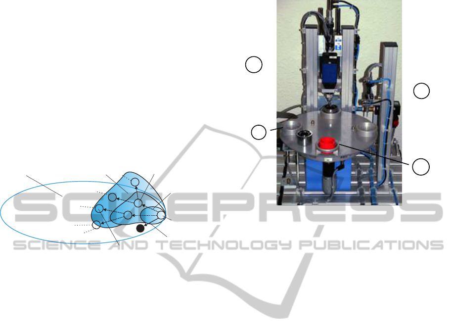
4 EXAMPLE
Figure 8 shows the processing station of a modular
production system in laboratory-scale. This process-
ing station consists of a rotary table with four posi-
tions. At positions
i
2
and
i
3
there are a drilling
module and a testing module. The purpose of this sta-
tion is to transport an incoming
i
1
work piece from
one table position to the next. At
i
2
the work piece
2
1
3
4
}
}
Figure 8: Processing station of a laboratory-scale produc-
tion system. The table positions are numbered clockwise
from 1 to 4 beginning at the left.
is processed (drilled). The drilling result is checked
at
i
3
. If the processing result is positive, the work
piece is ejected at position
i
4
. Otherwise it stays on
the table for reprocessing.
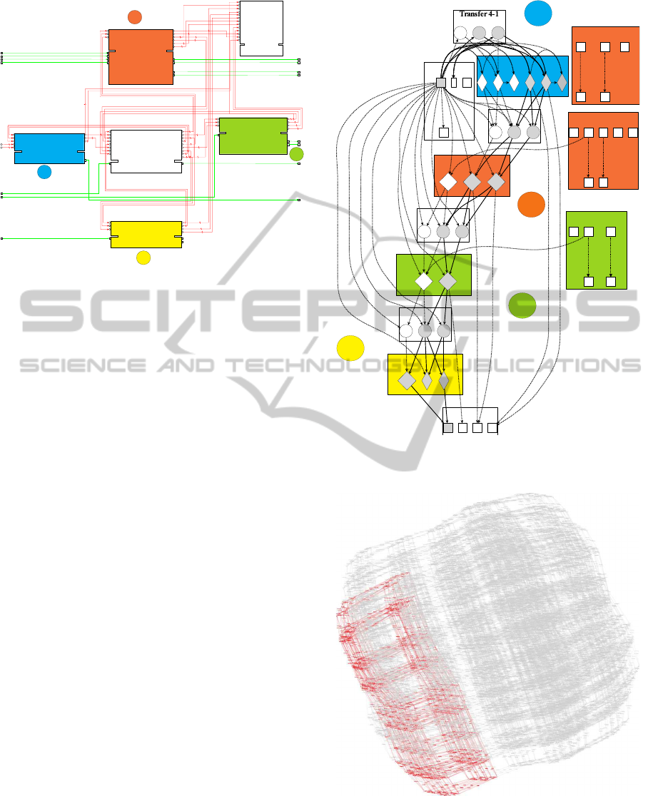
The plant architecture is reflected in the structure
of the
S
NCES model depicted in Figure 9. The mod-
ule in the middle represents the rotary table. The four
modules around represent the four table positions in-
cluding the modeling of the work piece properties
(presence and with hole) as well as the plant mod-
ules for drilling and testing. The upper module on the
right side of the image is the specification, modeled
as
S
NCEM. This specification is about the work piece
position, respectively the property presence, which is
modeled within the work piece properties at the dif-
ferent table positions.
The whole model consists of 73 places and 92
transitions which are organized in a modular hierar-
chy with 32 basic modules and 17 composite mod-
ules.
Figure 10 illustrates the results of the structural
analysis, respectively the TIG (Section 3.1), of the
plant model linked with the specification. For clar-
ity, the t-invariants covering the work piece properties
are diamond-shaped, whereas the t-invariants cover-
ing the property presence are gray-filled. The TIG in
Figure 10 illustrates the causal dependencies within
the plant model in Figure 9. Regarding the specifi-
cation, only TIG paths passing all table positions are
of interest. These paths are represented by the thick
solid edges in Figure 10.
PROCESS CONTROL SYNTHESIS IMPROVED BY STRUCTURAL MODEL PROPERTIES
349
Position 3
Specification
Position 2
Rotary Table
Position 1
Position 4
3
4
1
1
2
Figure 9:
S
NCES model of the processing station (Figure 8).
Each component group, which is shown in Figure 8 and the
specification are represented by a composite module. Due
to readability, not every detail is labeled.
This set of feasible paths and the specification of
forbidden states is used to perform the pRA (Section
3.2). The result of the pRA is shown in principle in
Figure 11. The highlighted part on the left of the
whole reachable state space represents the admissi-
ble state space determined by the pRA. A more de-
tailed representation would not be readable because
of more than 9,000 states of the whole state space,
which are strongly interconnected. The boundaries
of the highlighted admissible subspace, consisting of
256 states, are the starting points for the backward
search for controllable steps (Section 3.3).
With the presented approach, the complexity of
the state space analysis is reduced to an admissible
subspace of the whole reachable state space of the
model of the uncontrolled plant behavior. Thus, the
complexity of subsequent analysis steps is reduced
too, which is beneficial especially if regarding real
industrial-scale models.
5 CONCLUSIONS
Complexity has always been a crucial issue for for-
mal synthesis methodologies regarding real-size mod-
els. Therefore, in this contribution a novel approach
for discrete process control synthesis was presented,
which is based on a modular modeling formalism,
namely safe Net Condition/Event System. Structural
properties of this formalism were used to generate
an abstracted representation of the causal dependen-
cies within the plant model. These causal dependen-
cies were examined concerning their relevance with
Rotary Table
WP Properties Pos 1
Transfer 1-2
WP Properties Pos 2
Clamping Cylinder
Driller
Transfer 2-3
WP Properties Pos 3
Control Cylinder
Transfer 3-4
WP Properties Pos 4
Specification
3 1
1416
7
49
45 2
15
33
1719
50
3435
18
31
2022
51
8 9
48
10
6
32
21
1112
13
23 24 25
3637
39
38
40
4142
43 44
45 4647
27
30
28
29
26
4
3
2
1
Figure 10: TIG constructed from the
S
NCES model (Figure
9) of the processing station.
Figure 11: Reachability graph of processing station.
respect to the process behavior specification. The in-
corporation of these causal dependencies of the plant
model into a common state space analysis allow an
PECCS 2012 - International Conference on Pervasive and Embedded Computing and Communication Systems
350

efficient limitation of its computational complexity.
This reduces the complexity at a point which is crucial
for control synthesis, especially regarding large-scale
models of industrial size.
Accomplishing the research for the last step of the
presented approach is part of current and near future
work. The incorporation of timing issues is a goal
of subsequent research projects. In spite of this, the
current results are promising regarding an application
to industrial size systems.
ACKNOWLEDGEMENTS
This work is supported by the Deutsche Forschungs-
gemeinschaft (DFG) under reference numbers HA
1886/17-1 and HA 1886/17-2.
REFERENCES
Feng, L., Cai, K., and Wonham, W. M. (2009). A structural
approach to the non-blocking supervisory control of
discrete-event systems. International Journal of Man-
ufacturing Technology, 41(11–12):1152–1168.
Hanisch, H.-M. and Rausch, M. (1995). Net condition/event
systems with multiple condition outputs. In Proceed-
ings of the Conference on Emerging Technologies and
Factory Automation (ETFA), pages 592–600, Paris,
France.
Hirsch, M. (2010). Systematic Design of Distributed Indus-
trial Manufacturing Control Systems, volume 6. Lo-
gos Verlag Berlin.
Holloway, L., Krogh, B., and Giua, A. (1997). A survey
of petri net methods for controlled discrete event sys-
tems. Discrete Event Dynamic Systems: Theory and
Applications, 7(2):151 – 190.
Iordache, M. V. and Antsaklis, P. J. (2006). Supervision
Based on Place Invariants: A Survey. Discrete Event
Dynamic Systems, 16(4):451–492.
Li, Z. and Zhou, M. (2006). Two-Stage Method for Syn-
thesizing Liveness-Enforcing Supervisors for Flexi-
ble Manufacturing Systems Using Petri Nets. IEEE
Transactions on Industrial Informatics, 2(4):313–325.
Missal, D. and Hanisch, H.-M. (2006). Synthesis of dis-
tributed controllers by means of a monolithic ap-
proach. In Proceedings of the Conference on Emerg-
ing Technologies and Factory Automation (ETFA),
pages 356–363.
Missal, D. and Hanisch, H.-M. (2008a). A Modular Synthe-
sis Approach for Distributed Safety Controllers, Part
A: Modelling and Specification. In Proceedings of the
17th World Congress - The International Federation
of Automatic Control, pages 473–478, Seoul, Korea.
Missal, D. and Hanisch, H.-M. (2008b). A Modular Synthe-
sis Approach for Distributed Safety Controllers, Part
B: Modular Control Synthesis. In Proceedings of the
17th World Congress - The International Federation
of Automatic Control, page 14 47914 484, Seoul, Ko-
rea.
Missal, D. and Hanisch, H.-M. (2009). Synthesis of Dis-
tributed Safety Controllers with Incomplete State Ob-
servation. In 35th Annual Conference of the IEEE
Industrial Electronics Society (IECON), pages 4383–
4390, Porto.
Pinzon, L., Jafari, M., Hanisch, H.-M., and Zhao, P.
(2004). Modelling admissible behavior using event
signals. Transactions on Systems, Man and Cybernet-
ics (SMC) Part B: Cybernetics, 34 (3):1435–1448.
Starke, P. and Roch, S. (2002). Analysing signal-net sys-
tems. Technical Report 162, Humboldt-Universit
¨
at zu
Berlin, Berlin, Germany. Informatikberichte.
Uzam, M. and Wonham, W. (2006). A Hybrid Approach to
Supervisory Control of Discrete Event Systems Cou-
pling RW Supervisors to Petri Nets. The Interna-
tional Journal of Advanced Manufacturing Technol-
ogy, 28(7-8):747–760.
Winkler, T., Lapp, H.-C., and Hanisch, H.-M. (2011). A
new Model Structure based Synthesis Approach for
Distributed Discrete Process Control. In Proceedings
of the 9th IEEE International Conference on Indus-
trial Informatics (INDIN), pages 527–532, Caparica,
Lisbon, Portugal. IEEE IES.
PROCESS CONTROL SYNTHESIS IMPROVED BY STRUCTURAL MODEL PROPERTIES
351
