
MOSAIK - SMART GRID SIMULATION API
Toward a Semantic based Standard for Interchanging Smart Grid Simulations
Steffen Sch
¨
utte, Stefan Scherfke and Michael Sonnenschein
OFFIS, Escherweg 2, 26121 Oldenburg, Germany
Keywords:
Smart Grid, Co-simulation, Coupling, Semantic, Simulation Interface, Domain-specific Language, Distributed
Simulation.
Abstract:
Simulation is an important method to test and evaluate new control mechanisms for future Smart Grids. To
generate sound simulation results one has to use validated and established simulation models. In this paper we
present the first two out of six layers of our approach to a modular simulation framework, called mosaik. It will
allows to specify, compose and simulate Smart Grid scenarios based on the reuse of existing, technologically
heterogeneous simulation models. The layers presented here include a syntactic layer defining an interface
for Smart Grid simulators and a semantic layer implemented using a domain-specific language that allows to
describe the structure and semantics of the simulator that is interfaced.
1 INTRODUCTION
Nowadays the electricity grid undergoes a large struc-
tural change toward a so-called Smart Grid, among
other reasons triggered by the increased integration
of renewable energy sources. In the future, the power
grid will no longer be dominated by a relatively small
number of large coal and nuclear power plants, but
rather by a large number of dispersed, renewable en-
ergy sources (DER). The major problem thereby is
the coordination of this large number of DER such
that generation and demand are balanced at any time.
This is a challenging task due to the number and re-
strictions of the involved components. Control strate-
gies for this complex and new task still need to be
developed and in particular evaluated and tested, for
example with respect to grid stability or other scenario
specific objectives. To ensure that this transition pro-
cess can be done as economically as possible and es-
pecially without losing the reliability of today’s grid,
these control strategies need to be tested in simulated
Smart Grid scenarios first.
In order to yield sound and scientifically reliable
results, simulations have to rely on valid and (ideally)
established models. As a consequence, a lot of effort
is put into the modeling and validation of both single
system components such as photovoltaics or wind en-
ergy converters and composite sub-systems, e.g. en-
tire low or medium voltage power grids. Therefore, it
is desirable to reuse existing models in new projects
and simulation studies as much as possible. However,
a number of problems arises when reusing existing
simulation models to form new Smart Grid scenarios.
Physical Topology
Information Topology
2
3
1
Available simulations
Figure 1: Identified problem areas.
Figure 1 shows the problem areas that mosaik
aims to solve. First, the available simulators are usu-
ally not designed to be reused (1). Therefore they
do not offer any interface that is appropriate for in-
teracting with the executed simulation. Second, one
has to find a way to compose the different simulation
models in a flexible way such that different scenarios
can be composed and simulated (2). And finally, the
composed simulation has to allow the interaction with
control strategies (3). In our research we focus on
the integration of multi-agent based control strategies
which includes two major tasks. First, a standardized
API has to be offered to the agents such that different
14
Schütte S., Scherfke S. and Sonnenschein M..
MOSAIK - SMART GRID SIMULATION API - Toward a Semantic based Standard for Interchanging Smart Grid Simulations.
DOI: 10.5220/0003950100140024
In Proceedings of the 1st International Conference on Smart Grids and Green IT Systems (SMARTGREENS-2012), pages 14-24
ISBN: 978-989-8565-09-9
Copyright
c
2012 SCITEPRESS (Science and Technology Publications, Lda.)

strategies and simulation models can be interchanged
seamlessly. Second, a way to keep the agents syn-
chronized with the simulation time has to be found,
as multi-agent platforms are usually not made to work
with simulated environments (Gehrke et al., 2008).
To overcome these problems, we developed a con-
cept called mosaik (Sch
¨
utte et al., 2011) (Sch
¨
utte,
2011b) which allows the automatic composition of
Smart Grid scenarios as a test bed for control strate-
gies based on the reuse of existing simulators. This
also includes the use of available commercial simu-
lation packages. Inspired by the M&S architecture
proposed by (Zeigler et al., 2000, p. 496), the concept
is based on six layers as shown in figure 2.
Syntactic layer
Semantic layer
Scenario layer
Control layer
Current research/
first ideas presented
in (Schütte, 2011b)
Chapter 3
Chapter 4
(Scherfke and
Schütte, 2012)
Composition layer
Technical layer
Figure 2: Layers of the mosaik concept.
The technical layer provides a mechanism to find,
initialize and manage the available simulators at run-
time. The syntactical layer offers a generic simulator
API to make simulators interoperable. The semantic
layer formally describes parameter, models and enti-
ties of each simulator such that the semantic of the
data exchanged via the generic API is unambiguous.
The syntactic and semantic layer are described in de-
tail in this paper. The formal simulator descriptions
are then used in the scenario layer to formally de-
scribe Smart Grid scenarios. A scenario defines a cer-
tain composition and can also be used hierarchically
in other scenarios. Finally, the composition layer per-
forms the actual simulator composition based on the
formal scenario and simulator descriptions, and the
control layer allows to interact with the simulated en-
tities at runtime.
The rest of the paper is organized as follows. In
section 2 we present and discuss related work from
the Smart Grid and other domains. Section 3 intro-
duces the generic interface (SimAPI) proposed for
the syntactic layer. Section 4 introduces the semantic
layer. In this layer, the structure and semantic of each
simulator implementing the SimAPI is described in a
formal way using a domain-specific language (DSL)
we have developed for this purpose. We demonstrate
the usability of our SimAPI in section 5 by present-
ing a first simulation use case based on a prototypical
implementation. Finally, in section 6 we conclude by
discussing the current results and planned future en-
hancements.
2 RELATED WORK
Different tools and approaches for simulating Smart
Grid scenarios exist. (Karnouskos and Holanda,
2009) have “analyzed, designed, and built a simulator
based on software agents that attempts to create the
dynamic behavior of a smart city.” The advantages are
the possibility to observe and manipulate the behav-
ior of single entities (opposed to simulations that only
operate on static load profiles) and as such the evalua-
tion of a broad range of control strategies. As the sim-
ulation platform is based on the JADE agent frame-
work (JADE, 2012) and the Smart Grid, due to its
dispersed and large-scale nature, promotes the use of
agent based control strategies, these can be integrated
seamlessly into the simulator. However, the approach
does not consider the integration of existing simula-
tors/models, but rather requires to model all entities
of a Smart Grid scenario as JADE agents. GridLAB-
D (Chassin and Widergren, 2009) is a powerful sim-
ulation tool for power systems developed by the Pa-
cific Northwest National Laboratory (PNNL) in coop-
eration with industrial partners. It allows the specifi-
cation of a wide range of scenarios. However, com-
pared to GridLAB-D, the mosaik concept is designed
explicitly for the composition of heterogeneous simu-
lation models by using formal, semantically enriched
descriptions of the models and a powerful scenario
specification formalism, allowing to specify large sce-
narios with little code.
To our knowledge, no simulation interoperabil-
ity standard specific to the Smart Grid domain ex-
ists. Up to now, the military domain has been a ma-
jor driver for the development of simulation interop-
erability standards starting in the early 90s. This need
was initially triggered by the “need for a common
‘synthetic environment’ that could interconnect sim-
ulators in support of small-team training”. This can
be compared to today’s online games (Page, 2007).
The latest standard for distributed simulation that has
evolved from these efforts is the HLA. This standard
is very complex and thus hardly used outside the mil-
itary domain (Boer et al., 2008). We argue that this
is also true for Smart Grid simulations for the pur-
pose of evaluating and benchmarking control strate-
gies for distributed energy resources such as photo-
voltaics (PV), electric vehicles (EV) and other con-
trollable devices, as “new approaches [for simulation
interoperability] are unlikely to be accepted by the
M&S industry if they are connected with tremendous
MOSAIK-SMARTGRIDSIMULATIONAPI-TowardaSemanticbasedStandardforInterchangingSmartGrid
Simulations
15

migration costs due to reprogramming efforts” (Tolk
and Muguira, 2004). Therefore we present a very
lightweight interoperability solution for Smart Grid
simulation.
In the field of environmental sciences the OpenMI
(Gijsbers and Gregersen, 2005) standard is a suc-
cessful example for a lightweight and pragmatic
approach (which has been developed although the
HLA was already an IEEE standard when the work
on OpenMI began)
1
. However, there are fundamental
differences to the Smart Grid domain making the
OpenMI approach of manually connecting different
models inapplicable. Usually, few uncontrollable
models with complex interdependencies (e.g. a
river and a groundwater model) are analyzed in
the environmental domain while many models
of potentially controllable energy resources with
topological relationships characterize the Smart Grid
domain. Therefore, we decided to develop a Smart
Grid specific solution that allows (1) interfacing
and semantically describing simulators and their
models (presented in this paper), (2) describing
potentially large-scale Smart Grid scenarios and (3)
automatically composing these scenarios using the
available simulation models for purpose of evaluat-
ing control strategies (beyond the scope of this paper).
3 SYNTACTIC LAYER - SIMAPI
In this section we describe the requirements and de-
sign of a simulator API that we developed to achieve
basic, syntactic interoperability between the different
simulators.
3.1 Requirements
Although the SimAPI presented in this paper is not
Smart Grid specific in a technical way, we developed
it based on the analysis of different Smart Grid scenar-
ios we simulated in past projects and expect for future
projects. We identified three major requirements that
influenced the design of the SimAPI.
3.1.1 COTS Integration
As mentioned in the introduction it is important to
rely on valid and (ideally) established models. This
is especially true for the simulation models used for
the electrical infrastructure. For these models, differ-
ent (commercial-off-the-shelf) COTS simulators exist
1
http://www.openmi.org/documents/
OpenMI Newsletter1 0405.pdf
that have been used in industry and academia for a
long time. Therefore, the mosaik framework should
support the integration of such closed-source soft-
ware packages as well. For the syntactical layer, the
SimAPI should also be applicable to COTS simula-
tors, e.g. by implementing an adapter that mediates
between the SimAPI and API of the COTS compo-
nent.
3.1.2 Control Strategy Integration
Control strategies for all kinds of power grid re-
sources starting from a circuit breaker up to a pool of
several thousand electric vehicles are the major com-
ponents that distinguish the vision of the Smart Grid
from today’s less controlled power grid. For being
able to use composed simulation models as a test-
bed for the evaluation of new control strategies the
SimAPI has to provide information about the entity
relationships within a model.
For example, assume that we have the model of
a power grid comprised of an MV grid and differ-
ent LV grids. It has entities for transformers, buses
(nodes) and branches (power lines). Further we have
different models of controllable consumers and pro-
ducers. Now we want to use these models to form a
simulative scenario for assessing the performance of
a new multi-agent based control strategy. For such
multi-agent systems, different organization forms ex-
ist (Horling and Lesser, 2004). Let us assume we
have one agent per transformer (transformer agent)
and subordinate to this, one agent per controllable
resource (resource agent) in the subordinate LV grid
section and we have initialized the simulation models
by now. However, for initializing the agent system,
we need to know what resource agents are related to
which transformer agent.
Assuming that the grid topology is described by
a specific file, one way to get this information is to
include a parser into the control strategy code which
can read this file so that the grid topology can be nav-
igated for initializing the agents in the right topol-
ogy. However, different grid models may use different
file formats which makes it difficult to use other grid
models in this scenario and the parser code is more
or less redundant as the grid model has this informa-
tion anyway. Therefore we extended the SimAPI to
provide information about the model’s entity relation-
ships. This way, we can easily determine which nodes
are (via the branches) related to which transformer
just by querying the model without having to parse
any other files.
SMARTGREENS2012-1stInternationalConferenceonSmartGridsandGreenITSystems
16

3.1.3 Simulation Result Analysis
For being able to evaluate the performance of a con-
trol strategy, different metrics (e.g. resource utiliza-
tion) have to be calculated. The calculation of these
metrics is usually done based on the simulation results
(entity data that has been recorded during simulation).
For example, the maximum load of a transformer or
the maximum current through a power line could be
a possible metric. But how do we know what thresh-
olds are permissible? One way is to hard code the
values into the metric. However, it is much better to
obtain these values directly from the entity in ques-
tion. Therefore, the API must provide access to such
data describing static properties of the entities.
3.2 Abstraction Level
The syntactical layer is the lowest layer of our
concept, determining the possible interactions with
the simulation models. Therefore, a suitable ab-
straction level has to be chosen for the simulator
API that allows the integration of a broad range of
simulation models as well as sufficient flexibility
and detail for using these in different scenarios,
while at the same time being as simple as possible to
minimize integration effort and improve acceptance
of the SimAPI. As the mosaik framework focuses
on the composition of discrete event simulation
models (Sch
¨
utte et al., 2011), the lowest reasonable
abstraction level is the DEVS formalism introduced
by Zeigler (Zeigler, 1976). Although such a low-
level abstraction provides maximum flexibility, a
number of disadvantages arises. First of all, for the
integration of a simulation model (implementing
the SimAPI for this simulator) on this low abstrac-
tion level all low-level information (internal states,
state transitions, events, etc.) has to be integrated
into the SimAPI as well as described in a formal
way (see next chapter) to make it available for the
composition. Implementing such a complex API is
time consuming, error prone and likely to be rejected
by the users as “new approaches are unlikely to be
accepted [...] if they are connected with tremendous
migration costs due to programming efforts.” (Tolk
and Muguira, 2004) Furthermore, the integration
of simulation models based on COTS simulation
packages (see 3.1.1) is not likely to be possible on
this low abstraction level as such simulation packages
are usually not ”open” (Boer, 2005). Regarding the
last point, (Boer, 2005) did extensive research upon
distributed simulation in industry and defines three
different levels of ”openness” of COTS simulation
packages: ”fully open”, ”partly open” and ”fully
closed”. A fully open simulation package is a simula-
tion package that allows access to all entities and their
attributes at every step in time. (Boer, 2005) states
that according to this definition most of the available
simulation packages are only partly open. (Boer,
2005) therefore also uses a higher abstraction than
the DEVS formalism and only focuses on the entities
and their attributes without considering the internal
processes and events. (Zhang et al., 2005, p.3) use
a similar abstraction level since their approach for
oil reservoir performance forecasting is also based
on existing software and thus is “not concerned with
modeling the internal structures or implementation
of the building software components.” Instead they
“only capture the interfaces [of the components] each
of which can be characterized with a set of input
signals and a set of output signals”.
Assumption: An abstraction level as detailed as
the DEVS formalism is not required for compos-
ing the majority of Smart Grid scenarios.
On the other end of the scale a complete black
box view of a simulator could be assumed. Such an
API may only allow to read and manipulate certain
attributes of a simulation and advance the simulation
time step by step. Such an API is likely to be too
restricted.
3.3 Resulting Design
Based on the analysis of different simulation mod-
els we developed in our past Smart Grid projects, we
decided to let our SimAPI deal with 3 different con-
cepts:
1. Entity. Any object or component in the modeled
system that requires explicit representation (e.g.
a transformer, a power line, an electric vehicle)
(Banks et al., 2005)
2. Model. A (simulation) model is an abstract repre-
sentation of a system and is executed by a simu-
lation environment (e.g. a model of a low voltage
grid).
3. Simulator. A simulator is the execution environ-
ment for one or more models (in this paper, the
term simulation refers to a simulator, executing its
simulation models).
In other words, a simulator can contain one or
more models which again contain one or more en-
tities, representing objects in the real world. The
SimAPI has to account for this structure and allow
to specify the parameters for the simulator (start time,
step size, etc...), the number and configuration of the
MOSAIK-SMARTGRIDSIMULATIONAPI-TowardaSemanticbasedStandardforInterchangingSmartGrid
Simulations
17

models to execute as well as to access (read and write)
the attributes of the entities contained in the mod-
els. Entities cannot be simulated directly but rather
are the result of initializing a model in the simulator.
The possible step sizes of a simulation, the number
of models the simulator can handle and other non-
syntactic information will be part of the semantic de-
scription of the simulator (see next chapter).
Figure 3 shows the structure of a simulator and the
data that is made accessible by the SimAPI (arrows
crossing the black box).
Entity
Simulator
Model
1..*
1..*
0..*
Parameter
Parameter
Static Data
Time
Dyn. Data
Figure 3: Simulation features exposed by the API.
3.4 Implementation
The mosaik SimAPI is designed to be very generic
and flexible which allows a wide range of simula-
tions to be used with it. We use ØMQ (ZeroMQ) as a
message transport layer and JSON (JavaScript Object
Notation) for object serialization. ØMQ is fast, well-
documented, available on a wide range of platforms
(including Python, Java, C/C++) and freely avail-
able under the Lesser General Public License (LGPL)
(iMatix Corporation, 2012). JSON “is a lightweight
data-interchange format”. It is much more compact
and less verbose than XML and thus easier and faster
to read and parse (JSON, 2012). As opposed to e.g.
XML/RPC (Remote Procedure Calls with XML seri-
alization) which we used in an earlier prototype, using
ØMQ/JSON also allows us to asynchronously han-
dle multiple simulations at once without the need for
threading and locking. The mosaik framework cur-
rently offers a SimAPI adapter for simulations written
in Python. We also aim to provide adapters for at least
Java and C. The SimAPI adapters provided by mosaik
offer an interface for the SimAPI calls and take care of
the serialization of messages and the communication
with the mosaik framework (or any other client).
3.4.1 SimAPI Methods
The SimAPI consists of the following methods:
init (step size, sim params, model config):
Initializes a simulation and creates model in-
stances. model config contains a list of tuples pro-
viding information about how many instances of
what model have to be initialized with which pa-
rameter values.
get relations ():
Returns a list of tuples for each entity relation.
Each tuple contains a pair of related entities (their
IDs).
get static data ():
Returns the values of all static attributes for all
entities. Static attributes are attributes that don’t
change during the execution of the simulation.
get
data (model name, etype, attributes):
This methods returns the current values for all at-
tributes in attributes for all etype typed entities of
the model model name.
set data (data):
Sets the values of the given attributes for each en-
titiy in data, a list of tuples of an entity ID and
new attribute values for this entity.
step ():
Advances the simulation by step size steps (as de-
fined in the init method) and returns the current
simulation time.
3.4.2 The Low-level Communication Protocol
When a simulator has been started, it has to signal
the client (e.g. the mosaik framework) when it is
ready to receive commands. The client can then do
any number of SimAPI calls, that is sending simula-
tor commands and receiving their return value. When
the client is done, it sends a stop message, so that the
simulator can cleanly shut down itself.
Each message sent is a tuple containing the mes-
sage type (that is equivalent to the SimAPI method
name) and a dictionary with data which will be
mapped to the method parameters (see previous sec-
tion). Note that the client can send commands to mul-
tiple simulations at the same time and asynchronously
receive their replies. Figure 4 visualizes the commu-
nication sequences between the simulator and a client.
4 SEMANTIC LAYER
In the last section we defined a generic simulator API,
i.e. methods and their signature do not change from
SMARTGREENS2012-1stInternationalConferenceonSmartGridsandGreenITSystems
18

mosaik/Client Simulator
['sim_ready', sim_name]
['<sim_cmd>', params]
['sim_cmd_done',
['<sim_cmd>', return_value]]
['stop', {}]
repeat
Figure 4: The communication sequence between a simula-
tion and a client (e.g. mosaik).
one simulator to another. It allows to initialize, exe-
cute and access a simulator and its models and enti-
ties. Such a generic API is beneficial to integrate new
simulators into a simulation composition engine with-
out changing its implementation. But to allow the en-
gine and/or human clients to make correct use of the
simulators, additional information about the follow-
ing aspects of the SimAPI is required:
• What step sizes does the simulator support?
• What parameters are available for the simulator
and the models?
• What is their data type and what values are per-
missible?
• Which and how many models can a simulation ex-
ecute?
• How many models can a simulator execute and
can they have different parameter configurations?
• What entities does a model contain?
• What is the structure of the entities I/O-data?
• What static data is available?
We propose a domain-specific language (DSL)
called mosl (mosaik specification language) that is tai-
lored specifically for this purpose and allows to de-
scribe all these different aspects of a simulation in a
formal, human and machine readable way. We imple-
mented our DSL using the Xtext framework which
is available as a plugin for the Eclipse IDE. Both,
Xtext and Eclipse are freely available. Compared
to an XML based approach, for example, Xtext of-
fers a DSL specific editor with advanced consistency
checks, auto-completion, syntax highlighting and fur-
thermore the DSL has a custom syntax and is thus less
verbose (see (Xtext, 2011)).
Regarding the non-technical aspects, we try to
make use of the Common Information Model (CIM)
whenever it is possible and appropriate. The CIM pro-
vides a large information model for the energy do-
main and is standardized by standards series IEC
2
61970 and 61968. It is also recommended as one
of the core standards for the future smart grid (NIST,
2010).
Listing 1 shows the basic structure of our DSL us-
ing the example of a PowerFlow Simulator as we used
it in our first case study (see section 5). Although it is
very simple, it already covers a number of the aspects
listed above. Each simulator is described in a separate
file.
Listing 1: Basic simulation definition.
simulator Pow e r F l ow stepsize [1 ,] sec
model 1. . * S t a t i c Po w e rF l o w
entity B us
end
entity Branch
end
entity Tra n s fo r m e r
end
end
end
It allows to define a simulation and the valid step
sizes for this simulation as well as the possible mod-
els the simulation can execute. For each model, the
possible number of instances the simulation can exe-
cute can be defined (1 or more in the example), and
the entity types that the model contains are defined as
well. In the next sections we introduce the other con-
cepts of the DSL to define the remaining aspects of
the simulation based on this basic structure.
4.1 Simulation and Model Parameter
An important part of the DSL is the definition of con-
figuration parameters on both, simulation and model
level. A formal and standardized description of the
parameters as well as the standardized SimAPI to set
these parameters will ease model reuse, as the config-
uration of all participating simulators is specified in a
central place. According to our experience this is an
important point for increasing the usability of com-
posed simulations. Up to now, each simulator had to
be configured using its proprietary configuration file
format and location, making it very difficult to keep
track of the simulator configurations used for a sce-
nario. Listing 2 shows the parameter description us-
ing the example of an EV simulation.
2
International Electrotechnical Commission
MOSAIK-SMARTGRIDSIMULATIONAPI-TowardaSemanticbasedStandardforInterchangingSmartGrid
Simulations
19

Listing 2: Parameter definition.
simulator EVSim stepsize {1 , 15} min
start : d ate t i m e
stop : d a t etim e
model 1. . * identical EVMod e l
p_c h a r g e : float in W
{37 0 0 . 0 ,1 100 0 . 0 }
c_bat : float in Wh [1. 0 ,]
ini t _ s o c : float in p erce n t
[0.0 ,1.0 ] default = 0. 5
entity Vehicle
end
end
end
The definition of a parameter begins with a name
and a colon, followed by a data type. Currently,
possible types are int, float, string, boolean and
datetime. For numerical types an additional unit can
be specified using the ‘in’ keyword. The units that are
available have been extracted from the enumeration
UnitSymbol defined in the Domain package of the
CIM. For numerical types and the string type, the
definition of valid values is possible by either using
square brackets to specify a range or using curly
brackets to define a discrete set of allowed values.
The definition of a default value indicates the value
that is used by the model or the simulation when
the parameter is not provided via the SimAPI. The
keyword identical indicates that a single simulation
can only simulate the given number of models
with the same configuration parameters, i.e. the
simulation described above cannot simulate vehicles
with different battery sizes.
4.2 Data Flow and Composition
As already stated in the introduction, the work pre-
sented here is part of a larger concept (see figure
2)which will allow the automatic composition of dif-
ferent simulation models to form different Smart Grid
scenarios. Therefore, a model will usually be used
in combination with other models. This means that
the inputs and outputs of the different entities of the
models have to be connected. For example, the power
drawn by an EV, which is provided by the EV entity
as output value, is an input value for the Bus entity
which represents the node in the grid the EV is con-
nected to.
4.2.1 Reference Data Model
In order to allow such an automatic mapping, we pro-
pose the use of a reference data model that is used
for defining the entities’ inputs and outputs. Without
such a reference model a manual mapping would be
required between every possible combination of enti-
ties. By using the reference model this O(n
2
) prob-
lem is reduced to an O(n) problem (Tolk and Diallo,
2005, p.67) as the entities of a simulation model only
have to be adapted to the reference model (see figure
5). This adaption has to be done when implementing
and semantically describing the SimAPI. To base our
data model on a standardized and thus wide-spread
and solid basis we make again use of data structures
defined in the CIM whenever possible.
Simulator A
mosl
Simulator D
mosl
Simulator B
mosl
Simulator C
mosl
Reference
Data Model
Figure 5: Reference data model for semantic description of
simulator interfaces
The structure of the data that is consumed or pro-
vided by the entities (data flow) is of different com-
plexity. For example, information about the state of
charge (SOC) of a vehicle’s battery may be a simple
float value whereas the voltage of a node is a tuple
of voltage and angle and the power drawn by a con-
sumer is a tuple of active and reactive power. An EV
or other potentially controllable resources may also
be able to receive more complex data structures such
as operating schedules.
We have extended our DSL to allow the definition
of a reference data model with such complex struc-
tures by using a subset of the JSON-Schema (JSON-
Schema, 2012) specification. However, to keep our
DSL as readable and non-verbose as possible, we
chose not to use the JSON-Schema syntax but rather
a compatible notation syntax called Orderly (Orderly,
2012). This part of our DSL is based on an available
Xtext implementation of Orderly (Github, 2012), with
one exception: Orderly uses curly brackets to spec-
ify a range of allowed values. We decided to stick
to our syntax (using square brackets for ranges and
curly brackets for sets of allowed values) as this seems
much more intuitive and is well known from set the-
ory. Listing 3 shows the definitions of the different
entity data flow structures discussed above using our
DSL.
SMARTGREENS2012-1stInternationalConferenceonSmartGridsandGreenITSystems
20

Listing 3: Reference Data Model.
reference data model de . o f fis . mosaik
data flows
//IEC61970.StateVariables.SvPowerFlow
@Equals( vol t a g eL e v el )
Sv P o w er f l ow :object {
p :float in W
q :float in W
}
//IEC61970.StateVariables.SvVoltage
Sv V o l t ag e :object {
angle :float in rad
v :float in V
}
curr e n t :float in A
st a t eO f C ha r g e :float in p ercen t
[0.0 ,1.0 ]
v2 g _ sc h e d u l e :object {
st a r t T im e :datetime
ti m e P oi n t s :array [object {
time :integer in s
dur a t i o n :integer in s
comm a n d :string { idle , cha rge ,
di s c h a rg e }
power :float in W [0 .0 ,]
}]
}
end
static data
vo l t ag e L e v e l :string { LV , MV , HV }
//From IEC61970.OperationalLimits
Cu r r en t L i m i t :float in A
end
entity types //From IEC61970.Wires
AC L i ne S e gm e n t : Con d u c tor
Co n d u c to r
Bu s b ar S e ct i o n : Con n e c tor
Co n n e c to r
Jun c t i o n : Conn e c t or
end
end
The v2g schedule data, for example, is a complex
data type (object) with two fields. The field startTime
is a simple type representing a date, the field time-
Points is a list (array) of complex data types each of
which having the 4 fields time, duration, command
and power.
For the SvPowerflow and SvVoltage items we have
used the structures defined in the CIM. For the other
data, custom structures have been created. In addition
to the definition of the data structures, the reference
model also allows to define static data for the enti-
ties. As mentioned in 3.1.3, we define static data as
any data that describes an entity but does not change
over time. Besides using this static data when analyz-
ing the simulated scenario (see section 3.1.3) it can
also be used to specify domain-specific data flow con-
straints using the @Equals keyword. In this example,
we have defined that the voltage level of entities in-
terchanging SvPowerflow data must be the same. For
example, it must not be possible to connect an EV
(assuming EVs charge at the low voltage level) to a
bus in a medium voltage grid. As both entities have
to have the same attribute, it is defined in the refer-
ence data model as well, but within a special static
data section. The static data items can have the same
complex structure as the other items. Finally, the en-
tity types section allows to define a hierarchy of ab-
stract entity types. In our case the object hierarchy
defined in the IEC61970 package Wires is an appro-
priate option. The usage of these abstract entity types
is described in the next section.
The reference data model defines a unique names-
pace (here: de.offis.mosaik) as it is unlikely that
a globally standardized reference model will ever
be available. Using distinct namespaces, simulators
from different sources (companies) can be used to-
gether without mixing up data model elements with
the same name. Of course, in such cases a mapping
between the used reference data models has to be de-
fined. However, this is beyond the scope of the paper
and subject to future work.
4.2.2 Using the Reference Model
The mosaik scenario layer (see figure 2) will allow
to specify relations between the entities of different
simulators. Based on the semantic information in the
simulator description the data flows between any two
related entities shall then be derived automatically to
ease composition. The elements of the reference data
model provide the base for this process. They can be
referenced from within the simulator descriptions by
importing the corresponding namespace. The Xtext
framework natively supports the concept of names-
paces so that no further manual implementation is re-
quired. Listing 4 shows the final simulator description
for PowerFlow and EV simulator used in one of our
projects (see next section).
Defining the static data offered by the entities is
straight forward. It is simply defined using the static
keyword followed by a static data item from the ref-
erence data model. As with all other references, the
DSL editor generated by Xtext allows the user to use
only those elements that are defined in the reference
data model and thus supports the user in creating a
consistent simulator definition.
MOSAIK-SMARTGRIDSIMULATIONAPI-TowardaSemanticbasedStandardforInterchangingSmartGrid
Simulations
21

Listing 4: Defining static and dynamic data.
import de . o f fis . mosaik .*
simulator EVSim stepsize {1 , 15} min
model 1. . * identical EVMod e l
entity Vehicl e
static vo l t a ge L e ve l
port for 1 Conn e c t or
out gri d _ p ow e r : S v Po w e r Fl o w
end
port
cont r o l : v 2 g _ s c h ed u l e
end
end
end
end
simulator Pow e r F l ow stepsize [1 ,] sec
model 1. . * S t a t i c Po w e rF l o w
entity B us : Conn e c t o r
static vo l t a ge L e ve l
port for 0. . * //Can have n loads
in lo a d : S v P o we r f l ow
end
end
entity Branch : ACL i n eS e g me n t
static Cu r r e nt L i mi t
port
out i_br a n c h : c u r r e nt
end
end
entity Sla c k N o de : P o w er T r a n s fo r m e r
static vo l t a ge L e ve l //Primary side
port
out lo a d : S v P o we r f l ow
end
end
end
end
The dynamic data flow definition is slightly more
complex as these flows are the basis for simulation
composability. Generally, two entities (of models
from different simulators) can be connected when one
entity provides a data flow defined in the reference
data model and the other consumes it. To describe
these flow directions, each data flow is given a direc-
tion in the simulator description using either the in or
the out keyword. In case of an EV being connected
to a node in the power grid the EV will have an out-
going flow (the power it draws from the grid) and the
grid node has to provide an incoming flow. Further-
more, the allowed multiplicity for incoming flows can
be specified (depending on the type/capabilities of the
simulation model). In our example, it may be possi-
ble to connect multiple EVs to the same bus. In this
case it is the task of the simulator to aggregate the nu-
merous incoming flows to a meaningful value for the
underlying model entity.
Figure 6 shows a more complex scenario with an
EV having power flows to a bus (power drawn) and
power (kW)
power (kW)
SOC (%)
Connector Vehicle Storage
1 1
is a is a
Bus Vehicle LiPoBat
Figure 6: Port based entity composition.
a battery model (power drawn/charged). For both
flows, the same data item power is used. Note that
this is different to the reference model presented in
listing 3 but used for illustration purposes. With the
concepts defined so far, each outgoing flow of the
EV can be connected to both, the bus as well as the
battery, as the power flow is more abstract than our
SvPowerFlow which is to be used for AC power flows
only
3
. This is a general problem: A more abstract
flow increases the combination possibilities of an en-
tity but also increases semantic ambiguity. Of course,
one solution to this dilemma is to define different data
flows for AC (bus) and DC (battery). However it does
not tackle the general problem, which is a lack of se-
mantic. As mentioned before, data flows should be as
abstract as possible to increase combination possibil-
ities. We therefore added the concept of abstract en-
tities (see last section in listing 3) and introduced the
notion of ports. A port serves the purpose of grouping
all flows that are to be connected to an entity of a cer-
tain type (or all types if no type is specified). The type
of an entity is specified after its name using a colon.
In the example shown in figure 6, the EV entity de-
fines two ports: one for the connection to a Connector
in power grid and another for connecting the EV to a
Storage entity.
A port of an entity A can be connected to another
entity B when: (1) A has a port accepting B and B has
a port accepting A, (2) all incoming flows of each port
can be satisfied (i.e. type and direction match) and (3)
the domain specific data flow constraints are fulfilled.
Now the data flows can be established unambiguously
when composing the entities as shown in the bottom
part of figure 6. To avoid specifying the multiplicity
for incoming flows multiple times it has been moved
to the port definition as well.
5 A FIRST USE CASE
Within the eMobility project GridSurfer (BMWi,
3
Note: SvPowerFlow can still be used on different volt-
age levels but we therefore added the @Equals constraint in
the data model.
SMARTGREENS2012-1stInternationalConferenceonSmartGridsandGreenITSystems
22
2010), different simulators implementing the
SimAPI, as it has been presented here, have already
been successfully composed for the evaluation of
electric vehicle charging strategies (Nieße et al.,
2011). For this purpose, simulation models of electric
vehicles (Python/SimPy), photovoltaics (MAT-
LAB/Simulink), residential loads (CSV timeseries)
and two different distribution grids (rural and city
for a single-phase power flow simulator based on
Python/Pylon (Pylon, 2012)) have been composed
into a complex scenario. The analyzed scenarios
contained about 70 to 100 residential loads and
PV systems and 100 to 170 EVs, depending on the
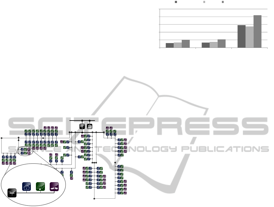
specific scenario. Figure 7 depicts the topology of
the used low voltage grid for the rural scenarios and
the entities of the different simulators that have been
integrated.
0.4 kV
20 kV
SimPy
Java/Matlab
Pylon
H0
CSV
PV
Matlab
EV
Python
Stat.
loadflow
Python
Figure 7: Topology of the simulated rural LV grid.
However, we only used a less powerful and flexi-
ble prototypical implementation of the mosaik layers
(figure 2) as partially described in (Sch
¨
utte, 2011a).
The consequences, for example, were a hard coded
control and data flow (execution order and I/O-
mapping) for the participating simulations. We de-
scribed the next generation of the semantic layer in
this paper and the remaining layers (scenario, com-
position and control layer) are subject to current and
future work. The mosaik framework will then be able
to dynamically determine the control and data flow
as well as to synchronize with potentially connected,
agent-based control strategies. Nevertheless, we ob-
tained different interesting results regarding the in-
tegration of renewable energy feed-in for the differ-
ent scenarios that we analyzed. We evaluated three
charging strategies for electric vehicles, namely un-
controlled charging, controlled charging and vehicle-
to-grid regarding their ability to store local feed-in
from photovoltaic power plants. Figure 8 shows the
aggregated and averaged results from several simula-
tion runs of the specified scenario. Since both the un-
20 0%
30,0%
40,0%
50,0%
P
V feed-in used
spring/autumn summer winter
0,0%
10,0%
20
,
0%
uncontrolled charging controlled charging vehicle-to-grid
percentage of
P
Figure 8: Percentage of local PV feed-in stored by electric
vehicles in a low voltage distribution grid using different
control strategies.
controlled and controlled charging strategy don’t take
the vehicles’ batteries ability to feed electric power
back to the grid into account, they can only use small
shares of PV feed-in (i.e., the electric power previ-
ously used for driving). In contrast, the vehicle-to-
grid agents fully exploit the batteries’ capabilities,
thus significantly increasing the percentage of used
PV feed-in.
6 CONCLUSIONS
The work presented here is, according to our knowl-
edge, the first attempt toward a Smart Grid specific
standard for simulation model exchange and interop-
erability. The generic SimAPI is intentionally kept
simple but allows to use a simulation for a broad range
of scenarios and provides a standardized way to com-
municate with simulators. The formal description of
each simulator’s API using the presented DSL serves
as a documentation and as the basis for an automatic
composition of simulated Smart Grid scenarios like-
wise. A concept for the latter has been presented in
(Sch
¨
utte et al., 2011) and a corresponding extension
of the DSL that will allow to describe complex scenar-
ios based on different simulations in a formal way is
currently under development. An in depth evaluation
of the overall mosaik concept will follow once this ex-
tension is available. Due to its high abstraction level,
the SimAPI will also be applicable to COTS simu-
lation tools. We currently develop such an adapter
for the broadly used tool PowerFactory (DiGSILENT,
2012). As the composability of simulation models de-
pends on the use of a common reference data model, it
will be beneficial to have a reference data model that
is not specific to a single institute or company. There-
fore, our work presented in this paper, as well as the
overall mosaik concept, will also be presented to the
Simulations Working Group of the Open Smart Grid
International Users Group (OpenSG, 2012), in which
one of the authors is actively involved right from the
beginning.
MOSAIK-SMARTGRIDSIMULATIONAPI-TowardaSemanticbasedStandardforInterchangingSmartGrid
Simulations
23

REFERENCES
Banks, J., Carson, J. S., Nelson, B. L., and Nicol, D. M.
(2005). Discrete-Event Simulation. Prentice Hall, 4th
edition.
BMWi (2010). Gridsurfer - inter-urbane integration
von elektrofahrzeugen in energiesysteme inklusive
batteriewechselkonzept. http://www.ikt-em.de/de/
GridSurfer.php.
Boer, C. A. (2005). Distributed Simulation in Industry. PhD
thesis, Erasmus University Rotterdam.
Boer, C. A., de Bruin, A., and Verbraeck, A. (2008). Dis-
tributed simulation in industry - a survey part 3 - the
hla standard in industry. In Proceedings of the 2008
Winter Simulation Conference, pages 1094–1102.
Chassin, D. P. and Widergren, S. E. (2009). Market op-
erations. Power & Energy Society General Meeting,
2009. Pes ´09, pages 1–5.
DiGSILENT (2012). DIgSILENT GmbH - software - digsi-
lent powerfactory. http://www.digsilent.de/Software/
DIgSILENT PowerFactory/.
Gehrke, J. D., Schuldt, A., and Werner, S. (2008). De-
signing a Simulation Middleware for FIPA Multia-
gent Systems. In 2008 IEEE/WIC/ACM International
Conference on Web Intelligence and Intelligent Agent
Technology, pages 109–113. IEEE.
Gijsbers, P. J. A. and Gregersen, J. B. (2005).
The OpenMI Standard in a nutshell. http://
www.openmi-life.org/downloads/documentation/the
openmi standard in a nutshell.pdf.
Github (2012). crealytics/orderly-json-xtext - GitHub.
https://github.com/crealytics/orderly json xtext.
Horling, B. and Lesser, V. (2004). A survey of multi-agent
organizational paradigms. Knowl. Eng. Rev., 19:281–
316.
iMatix Corporation (2012). ZeroMQ – the intelligent trans-
port layer. http://www.zeromq.org/.
JADE (2012). JADE - Java Agent DEvelepment Frame-
work. http://jade.tilab.com/.
JSON (2012). Introducing JSON. http://www.json.org/.
JSON-Schema (2012). Json schema. http://
json-schema.org.
Karnouskos, S. and Holanda, T. N. D. (2009). Simulation of
a Smart Grid City with Software Agents. 2009 Third
UKSim European Symposium on Computer Modeling
and Simulation, pages 424–429.
Nieße, A., Tr
¨
oschel, M., Scherfke, S., Sch
¨
utte, S., and Son-
nenschein, M. (2011). Using electric vehicle charg-
ing strategies to maximize pv-integration in the low
voltage grid. In 6th International Renewable Energy
Storage Conference and Exhibition (IRES 2011).
NIST (2010). NIST framework and roadmap for smart
grid interoperability standards, release 1.0. nist spe-
cial publication 1108.
OpenSG (2012). Home - SG Simulations. http://
osgug.ucaiug.org/SG Sim.
Orderly (2012). Orderly JSON. http://orderly-json.org/.
Page, E. H. (2007). Theory and practice for simulation in-
terconnection: Interoperability and composability in
defense simulation. In Fishwick, P. A., editor, CRC
Handbook of Dynamic System Modeling, chapter 16.
CRC Press.
Pylon (2012). Welcome - pylon home. http://
rwl.github.com/pylon/pylon/.
Scherfke, S. and Sch
¨
utte, S. (2012). mosaik - simulation en-
gine architecture. http:// mosaik.offis.de/ downloads/
mosaik architecture 2012.pdf.
Sch
¨
utte, S. (2011a). A domain-specific language for simu-
lation composition. In Burczynski, T., Kolodziej, J.,
Byrski, A., and Carvalho, M., editors, 25th European
Conference on Modelling and Simulation, pages 146–
152, Krakow.
Sch
¨
utte, S. (2011b). Composition of simulations for the
analysis of smart grid scenarios. In Energieinformatik
2011, pages 53–64. Prof. Dr. Dr. h.c. H.-J
¨
urgen Appel-
rath, Clemens von Dinther, Lilia Filipova-Neumann,
Astrid Nieße, Prof. Dr. Michael Sonnenschein and
Christof Weinhardt.
Sch
¨
utte, S., Scherfke, S., and Tr
¨
oschel, M. (2011). Mosaik:
A framework for modular simulation of active compo-
nents in smart grids. In 1st International Workshop on
Smart Grid Modeling and Simulation (SGMS), pages
55–60. IEEE.
Tolk, A. and Diallo, S. (2005). Model-Based Data Engi-
neering for Web Services. IEEE Internet Computing,
9(4):65–70.
Tolk, A. and Muguira, J. A. (2004). M&s within the model
driven architecture. In Interservice/Industry Training,
Simulation, and Education Conference (I/ITSEC).
Xtext (2011). Xtext 2.0 documentation. http://
www.eclipse.org/ Xtext/documentation/2 0 0/000-
introduction.php#DSL.
Zeigler, B. P. (1976). Theory of Modelling and Simulation.
Wiley & Sons, New York.
Zeigler, B. P., Kim, T. G., and Praehofer, H. (2000). Theory
of Modeling and Simulation. Academic Press, New
York, 2nd edition.
Zhang, C., Prasanna, V., Orangi, A., Da Sie, W., and Kwa-
tra, A. (2005). Modeling methodology for application
development in petroleum industry. IRI - 2005 IEEE
International Conference on Information Reuse and
Integration., pages 445–451.
SMARTGREENS2012-1stInternationalConferenceonSmartGridsandGreenITSystems
24
