
SMART GRIDS WITH ELECTRIC VEHICLES:
THE INITIAL FINDINGS OF PROJECT REIVE
A Project Funded by the Portuguese Ministry of Economy, Innovation and
Development
F. J. Soares, C. Gouveia, P. N. Pereira Barbeiro, P. M. Rocha Almeida, C. Moreira
and J. A. Peças Lopes
INESC TEC – INESC Technology and Science (formerly INESC Porto) and FEUP – Faculty of Engineering, University of
Porto, Campus da FEUP, Rua Dr. Roberto Frias, 378, 4200 – 465, Porto, Portugal.
Keywords: Electric Vehicles, Micro-generation, Smart Charging, Smart Grids, Smart Metering.
Abstract: This paper provides a general overview of the initial developments in the REIVE project (Smart Grids with
Electric Vehicles). The main focus of the project is on smart grid infrastructures for large scale integration
of EV and micro-generation units. It is a natural evolution of the InovGrid project promoted by the EDP
Distribuição – the Portuguese Distribution Network Operator – and allows the development of seminal
concepts and enabling technological developments within the Smart Grid paradigm. This paper presents the
management and control architecture developed to allow electric vehicle integration in smart grid operation.
Additionally, it presents the major impacts in distribution grids of the simultaneous deployment of electric
vehicles, micro-generation and smart grid technologies.
1 INTRODUCTION
The integration of Electric Vehicles (EV) in
electricity grids presents numerous challenges in
terms of grid infrastructure, as well as in terms of
management and control capabilities of these entities
(Clement-Nyns et al., 2010, Galus et al., 2010). The
smart grids paradigm is possibly the only effective
way to cope with these new challenges. The
expected large scale deployment of intelligent
equipment’s on the grid in the near future is,
therefore, a unique opportunity to define innovative
features and functionalities (Lopes et al., 2006,
Lopes et al., 2011), which will allow a larger and
safer integration of micro-generation (μG) units and
EV, as well as the implementation of more
ambitious Demand Side Management (DSM)
solutions and control strategies (Callaway and
Hiskens, 2011, Xu et al., 2010).
The project REIVE – Smart Grids with Electric
Vehicles (Redes Inteligentes com Veículos
Eléctricos in the Portuguese designation) addresses
this problematic in a holistic manner. It exploits
synergies between all the elements that compose a
smart grid, especially focusing on μG units and EV.
The project can be regarded as an extension of an
on-going project led by the Portuguese Distribution
System Operator (DSO) – the InovGrid project
(Messias, 2009). InovGrid is focused on the
development of a fully active distribution network
introducing advanced DSM strategies where
common energy consumers are able to play an active
role in the consumption management and also be
micro-producers. The interaction between
consumers/micro-producers units and the network
operator is assured through the functionalities
provided by the strategically developed equipment,
such as “energy boxes” and “distribution
transformer controllers”, as well as a proper
communications infrastructure. The smart grids
framework envisaged in the InovGrid project allows
not only to optimize consumers energy consumption,
but also improving transmission and distribution
networks effectiveness, decreasing technical losses,
reducing metering costs, postponing network
investments, improving and monitoring quality of
service, among other benefits.
Following the findings of the InovGrid project, a
39
Soares F., Gouveia C., Barbeiro P., Almeida P., Moreira C. and Lopes J..
SMART GRIDS WITH ELECTRIC VEHICLES: THE INITIAL FINDINGS OF PROJECT REIVE - A Project Funded by the Portuguese Ministry of
Economy, Innovation and Development.
DOI: 10.5220/0003953500390048
In Proceedings of the 1st International Conference on Smart Grids and Green IT Systems (SMARTGREENS-2012), pages 39-48
ISBN: 978-989-8565-09-9
Copyright
c
2012 SCITEPRESS (Science and Technology Publications, Lda.)

demonstration pilot was launched, named InovCity,
in Évora, which is a city in the south of Portugal
with c.a. 32000 customers. The main objective of
InovCity is to test the solutions developed in the
InovGrid project and to quantify the technical and
economic benefits yielding from the approaches
implemented (Giordano et al., 2011).
The project REIVE aims at upgrading the
functionalities of the InovGrid’s “energy box” and
developing a technical platform, where innovative
features that allow the progressive integration of μG
and EV are developed and tested. Both technical and
commercial domains are addressed. The strategic
value and scope of the project covers contributions:
For the industrialization of technologies and
products by industrial partners;
To the mobility paradigm shift, by setting
technical conditions from the grids side for
increasing levels of EV deployment;
To reduce CO
2
emissions, by allowing the
sustained usage of EV penetration combined
with further integration of intermittent
Renewable Energy Sources (RES).
The project REIVE also contemplates the
implementation of a smart grid in a laboratorial
environment, where it will be possible to test the
performance of new control and management
concepts for facilitating DER and EV integration in
LV networks. Additionaly, the laboratorial facilities
will also be used in order to develop new prototypes
for smart grid network controlers and power
electronic interfaces for EV and μG, which will
integrate the functional specifications undertaken
during the project development.
This paper presents the initial findings of the
project REIVE, with a special emphasis on the
control architecture developed, on the impacts
resulting from large scale depployment of μG units
and EV in distribution networks and on the smart
grid test bed that is being conceptualized for near
future implementation in laboratorial environment.
2 MANAGEMENT AND
CONTROL ARCHITECTURE
As referred in the previous section, the project
REIVE seeks to develop advanced management and
control mechanisms to facilitate the large scale
integration of EV and μG units in the power system,
using, as basis, the concepts and approaches
developed within the InovGrid project. The
InovGrid project was initiated in 2009 by the
Portuguese DSO, with support of INESC Porto,
Janz, Efacec and Logica.
The advanced infrastructures and functionalities
developed within InovGrid enable the
implementation of new commercial services,
allowing the active participation of the
consumers/micro-producers in both the electricity
market and system operation. From the system
operator point of view, the concept developed
promotes a more efficient renovation of the
distribution network infrastructures and management
systems, implementing investments that enhance
reliability and efficiency, and increasing the
capabilities of remote control and automation
systems.
The architecture of the system is represented in
Figure 1. It expands the utilities monitoring and
control capability downstream the MV network to
the consumers premises. This architecture is
constituted by 4 layers, defined according to the
identified players: the Energy Boxes (EB) installed
at the clients premises, the Distribution Transformer
Controllers (DTC) installed at the MV/LV
substations, the Smart Substation Controller (SSC)
installed at the HV/MV substations and the central
systems, namely the Distribution Management
System (DMS) and the commercial systems for
clients account managment purposes, which includes
only commercial information. As shown in Figure 1,
this architecture relies in communication network
allowing the communication within the same layer
and with the other layers.
2.1 Energy Box
The EB is a smart metering equipment to be
installed at the consumers/micro-producers premises
with bi-directional communication capability. The
EB functionalities include remote metering of
power, as well as other parameters related to the
number and duration of interruptions and also
voltage monitoring functionalities. In addition, the
EB also includes other functionalities for consumer
management purposes, such as: remote modification
of the contracted power, remote modification of
tariff regimes and remote interruption of fraudulent
clients. The EB was conceived modularly, thus
allowing the inclusion of a set of interface modules,
which enable the interaction with other home energy
management systems. Three different versions of the
EB were developed, which are capable of providing
different services, in order to face different
customers’ needs: an EB for simple consumers
(EB1), an EB for customers that own micro-
generation units (EB2) and an EB for customers that
SMARTGREENS2012-1stInternationalConferenceonSmartGridsandGreenITSystems
40
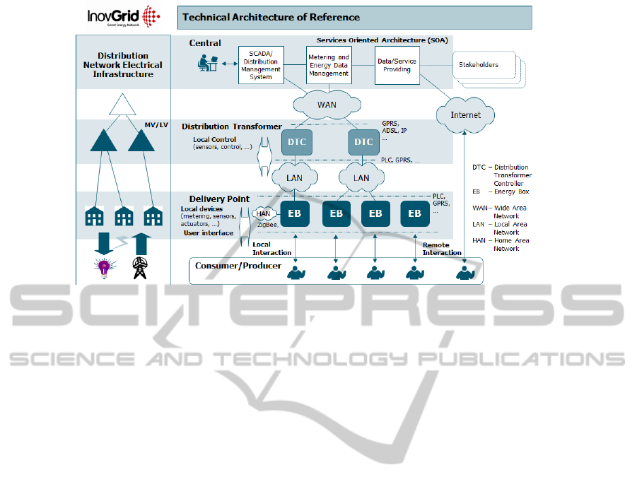
Figure 1: InovGrid advanced management and control system architecture.
own EV and wish to participate in controlled EV
charging schemes, such as smart charging (EB3).
Differentiating the EB according to their
functionalities enables the customers to acquire an
EB adapted to their specific needs, avoiding the
obligation of all customers acquiring equipment with
an increased cost and with useless advanced
processing capabilities.
The EB is prepared to receive control signals
from the entities in the upper hierarchical levels of
the control architecture developed within InovGrid
(see
Figure 1), which will vary according to the
version of the EB. EB1 include the base EB
functionalities such as remote metering and the
possibility of performing an on/off control over the
EV that are charging. This EB also allows the
remote change of commercial agreement conditions
such as change of tariffs or contracted power. EB2
and EB3 include several interface modules capable
of receiving specific control signals from the entities
in the upper hierarchical levels that will enable the
μG unit’s dispatch and the EV participation in
controlled charging schemes. In addition, EB3 also
enables the provision of several ancillary services by
EV, like reserves delivery.
2.2 Distribution Transformer
Controller
The DTC is installed at the MV/LV distribution
network substations. It receives and processes the
data collected from all the EB downstream and
sends it to the higher control layers. At the same
time, it will also receive information from the central
systems and distribute the information or the
resulting control signals to the downstream EB. On
more advanced version of the InovGrid system, the
DTC will also include functionalities that enable
them to manage the operation of the local networks,
both in normal and emergency conditions.
2.3 Smart Substation Controller
The SSC is responsible for coordinating the active
players of the MV networks as well as the DTC
installed in the MV/LV substations. The SSC
functionalities include intelligent algorithms to
optimize energy flows and network topology, as
well as self-healing algorithms, in close coordination
with network operators via the SCADA/DMS. It
also has the capability of performing coordinated
voltage control and detecting faults in an effective
manner, contributing to smaller restoration times and
reducing the number of clients affected by the faults.
The SSC is in fact very similar to the Central
Autonomous Management Controller (CAMC)
entity, developed within the MORE-MICROGRIDS
Project, which main purpose is the management of
the Multi-Microgrid (Gil and Lopes, 2007).
2.4 Integration of EV in the InovGrid
Architecture
The large scale deployment of plug-in EV will
require new charging interface infrastructures, such
as fast charging stations, public and domestic
charging points and private charging stations
dedicated to EV fleets. With exception of the fast
SMARTGRIDSWITHELECTRICVEHICLES:THEINITIALFINDINGSOFPROJECTREIVE-AProjectFundedby
thePortugueseMinistryofEconomy,InnovationandDevelopment
41

charging stations, all the other infrastructures will
provide a slower charging, that can take up to 8
hours. For this reason, it is expected that EV will be
connected to the grid for large periods of time, being
potentially possible to exploit their storage capacity
in order to enable a better usage of the network
infrastructures.
Yet, the decision of the EV participating or not in
controlled charging schemes will always be a
decision taken by their owners. For this reason,
several possible charging schemes should be
available in order to fit the specific needs of the EV
owners.
In the non-controllable charging strategies, the
EV is envisioned as a conventional load, being the
EV owner free to charge the vehicle in any time of
the day. In the dumb charging mode the EV behave
has any other appliance, having no restrictions or
incentives to shift their charging to the lower
consumption periods. In order to provide load
shifting, a multiple tariff policy may be implemented
to incentivize the EV to charge the batteries in the
periods were the electricity price is lower. This
method is based on the dual tariff scheme
implemented in several countries, where during
valley hours the electricity price is lower. However,
as this is not an active management strategy, the
success of this method depends on the EV owner
willingness to take advantage of this policy, and thus
only part of the EV load would eventually shift
towards valley hours.
In the controllable strategies the EB3 will receive
specific control signals to control the EV battery
charging. The objectives may be commercial or to
ensure the secure operation of the system. The smart
charging strategy envisions an active management
system, where there are two hierarchical control
structures, one headed by an EV aggregating agent
and other by the DSO.
In normal operating conditions, the EV charging
will be managed and controlled exclusively by a
commercial aggregator, whose main functionality is
to cluster the EV, according to their owners’
willingness, and exploit business opportunities in the
electricity markets. In order to successfully respect
the agreements, both with the clients and with the
electricity market, the EV aggregator must be
capable of sending set-points to the EB3 related with
rates of charge or requests for provision of ancillary
services. Whenever the security of operation is
compromised, i.e. when the grid is being operated
near its technical limits, or in emergency operating
modes, e.g. islanded operation, the system operator
overrides the aggregator control signal, in order to
control the EV charging. This type of EV charging
management provides the most efficient usage of the
resources available at each moment, enabling
congestion prevention and voltage control, while
avoiding the need to invest largely in network
reinforcements.
In the V2G charging mode, the EV charging
interface admits bi-directional power flow, enabling
the EV to inject active power into the grid. From the
grid perspective, this is the most interesting way of
using EV capabilities, given that besides helping
managing branches’ congestion levels and voltage
related problems in some problematic spots of the
grid, EV have also the capability of providing peak
power in order to make the energy demand more
uniform along the day and to perform primary
frequency control. Nevertheless, there are also some
drawbacks related with the batteries degradation.
Batteries have a finite number of charge/discharge
cycles and its usage in a V2G mode might represent
an aggressive operation regime due to frequent shifts
from injecting to absorbing modes. Thus the
economic incentive to be provided to EV owners
must be even higher than in the smart charging
approach, so that they cover the eventual battery
damage owed to its extensive use.
The additional storage capacity provided by EV
has also the potential to enhance grids’ resilience,
namely regarding isolated systems, improving the
frequency response and increasing the amount of
renweable-based μG that can be safely integrated in
the system (Lopes et al., 2009). The V2G control
strategies for frequency regulation adopted in project
REIVE are based on the ω-P characteristics
represented in Figure 2. The EV will change its
power output based on the isolated grid frequency in
order to reduce the imbalance between generation
and load. For frequencies around 50 Hz the EV
charge its battery at its nominal power. A dead-band
is considered in order to avoid the degradation of EV
batteries resulting from frequent solicitations for
small frequency deviations. When the frequency
drops below the dead-band minimum, the EV
reduces its power consumption and if the frequency
drops further bellow the zero-crossing frequency
(f
0
), the EV starts to inject power into the grid.
When the grid frequency increases to values superior
to the dead-band maximum, the EV increases
gradually its power consumption until the maximum
possible power consumption is reached.
The parameters of the frequency-droop
characteristic will depend on the EV charger
characteristics and on the willingness of EV owners
to participate in such services. These parameters
SMARTGREENS2012-1stInternationalConferenceonSmartGridsandGreenITSystems
42

may differ from grid to grid and can be remotely
changed by the DTC, in order to coordinate the EV
participation with the other grid frequency
regulation mechanisms (load shedding schemes and
availability of energy storage devices).
Figure 2: EV frequency-droop characteristic.
3 IMPACTS OF MICRO-
GENERATION AND EV IN
DISTRIBUTION NETWORKS
The large deployment of EV is very likely to
provoke changes in the power demand patterns,
causing changes in the grids’ voltage profiles,
branches’ congestion levels and energy losses,
namely at the distribution level, where the EV will
connect for charging purposes (Lopes et al., 2011).
The identification of the control and management
strategies described in section 2 of this paper was
complemented by an exhaustive evaluation, in a
steady-state framework, of the impacts that EV
charging and µG will have in the system operation.
The evaluation performed, required the development
of an innovative methodology to assess the referred
impacts in the Portuguese distribution system (LV +
MV networks). Different EV charging strategies
were also considered, as well as several future μG
and EV penetration scenarios.
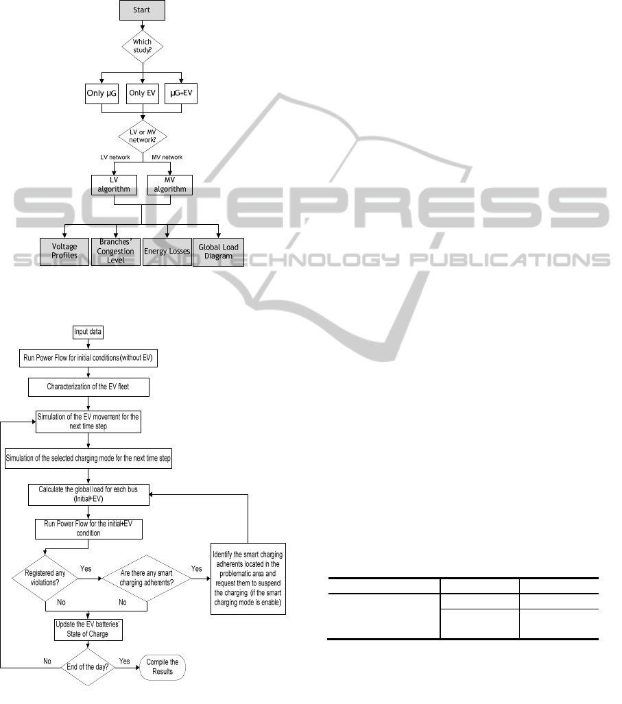
3.1 Methodology
The main objective of the steady-state studies
performed under the REIVE project was to assess
the impact of the µG and EV in the Portuguese
distribution system. Due to the large extension of the
network and consequent simulation complexity,
some general assumptions were made, namely:
Separate analysis of LV and MV networks;
Only the LV and MV networks with the
highest degree of representativeness of the
Portuguese distribution system were
selected;
Load and generation diagrams are
represented by a discrete time step of half an
hour, being conducted one power flow for
each time step.
Under these assumptions, the impact assessment
studies were conducted for each selected network,
using a simulation tool that provides a reliable and
detailed characterization of the grid operating
conditions. The outputs of this tool are voltage
profiles, branches' loadings, grid peak power, energy
losses and the identification of networks components
that will possibly be operated near, or above,
technical limits. The general methodology adopted is
shown in Figure 3.
To obtain a detailed evaluation, three studies
were performed considering: a) Only the connection
of EV; b) only µG; c) both EV and µG connections.
The first two studies, which address separately the
EV and μG integration in the system, were
performed in order to assess more accurately the
individual impacts of each technology.
In order to assess the importance of controlling
EV load, the dumb charging, multiple tariff scheme
and smart charging strategies were considered in the
studies a) and c). The V2G concept was not included
in the steady-state simulations, since its main
contribution is for the transient stability of the
system, requiring dynamic studies that are currently
on-going. As these studies were not concluded yet,
their results will not be presented in this paper.
The developed tool combines a stochastic model
based on a Monte Carlo method with the PSS/E tool
for electric grid simulation purposes, according to
the principles described in (Rosa et al., 2011). The
algorithm associated with this evaluation suite is
represented in Figure 4.
After evaluating the initial conditions of the grid
under study, the stochastic model based on a Monte
Carlo method is used to characterize the EV
regarding different EV drivers’ behaviours, EV
charging strategies, battery capacities, charging rates
and energy consumptions per distance travelled
(kWh/km). Then, it simulates EV movement and
charging for each ½ h period of a day.
Regarding the modelling of the µG units, the
power produced by each µG unit is subtracted to the
existing load at each bus for each time step of the
simulation, as in (Barbeiro et al., 2010). µG units are
allocated to the buses proportionally to the
residential load installed in each bus and it is
considered that they have unity power factor. EV are
distributed through the grid according to a set of
P
f
Dead
Band
EV consumption
P
max
P
min
P
In
j
ection
P
Consum
p
tion
f
0
f
neg
SMARTGRIDSWITHELECTRICVEHICLES:THEINITIALFINDINGSOFPROJECTREIVE-AProjectFundedby
thePortugueseMinistryofEconomy,InnovationandDevelopment
43
probabilities, proportional to the residential load
installed in each bus. Therefore, the buses with
higher residential loads installed will have larger µG
units connections and a higher probability of having
EV parked.
Figure 3: Methodology adopted for the µG and EV impact
evaluation.
Figure 4: Algorithm to evaluate EV impacts.
3.2 Simulation Scenarios
The steady-state simulations required the definition
of the EV and μG integration scenarios, as well as a
detailed characterization of the distribution
networks.
3.2.1 μG Integration Scenarios
In the analysed scenarios, 80% of all the μG units
considered were assumed to be photovoltaic, while
the remaining 20% were assumed to be micro-wind
turbines. All the μG units are considered to operate
at unity power factor and can be generally
characterized by specific generation patterns, which
depend on the technology specificities. The Decree-
Law No. 363/2007 establishes the legal regime
applicable to electricity production through μG
units, stating for the year of 2008 a maximum power
capacity of 10 MW that could be subsidized. This
value is successively increased at a rate of 20% per
year up to 2015. Based on this legal frame and as in
(Barbeiro et al., 2010), two μG integration scenarios
were considered:
Scenario A – μG installed capacity at
national level grows at a rate of 20% until
2015 and 3% from 2016 to 2030, reaching
250MW of installed capacity in 2030.
Scenario B – μG installed capacity at
national level grows at a rate of 65% until
2015 and 6% from 2016 to 2030, reaching
2000MW of installed capacity in 2030.
3.2.2 EV Integration Scenarios
Since the aim of this study is to assess the impact of
the EV in the distribution grids, it is of utmost
importance to define a reasonable set of hypothesis
for EV integration until 2030. In this paper two
scenarios of EV deployment were defined,
considering two different automobile replacing rates
and attending to the social and political
circumstances.
Table 1: Nr. of BEV and PHEV (thousands of units).
PHEV BEV
2020 2030 2020 2030
High variant (103)
168 444 84 1035
Low variant (103)
114 422 76 281
Additionally, the scenarios defined differentiate
the growth of the two main types of vehicles that are
expected to be deployed: the battery EV (BEV) and
the plug-in hybrid EV (PHEV). The number of EV
expected to be integrated in the Portuguese fleet by
2020 and 2030 is presented in Table 1.
SMARTGREENS2012-1stInternationalConferenceonSmartGridsandGreenITSystems
44
3.2.3 Portuguese MV and LV Distribution
Networks
As it was previously referred, the presented studies
were performed on a set of LV and MV Portuguese
distribution networks, based on real data. For the LV
simulations, five typical LV networks were used,
classified according to their MV/LV transformer
rated power, which is a satisfactory approximation
of load density. Regarding the MV networks
existing in Portugal, six typical MV networks were
identified. The load and topological characteristic of
these networks are assumed to be representative of
different parts of the overall MV distribution grids in
Portugal. In terms of distributed energy, the six MV
grids approximately represent a geographical area
totalizing approximately half the total energy
consumption registered in the whole Portuguese MV
distribution network. A detailed description of these
networks can be found in (Barbeiro et al., 2010).
In 2010, the annual consumption in the entire
Portuguese distribution network was approximately
44.7 TWh. Considering the evolution of the
Portuguese electricity consumption in recent years
and the current economic and financial situation, a
load growth rate of 1.5% per year was considered
for a time horizon from 2010 to 2030.
The load diagrams adopted for this study were
based in the diagrams used in (Barbeiro et al., 2010).
The study considers two different periods in a year –
winter and summer. For the MV, it is possible to
distinguish three types of consumers: residential,
commercial (both at the aggregate level of the
MV/LV substation) and industrial (consumers fed
directly at MV level). In LV grids only residential
and commercial consumers were considered, since
the number of industrial consumers does not have
significant relevance.
3.3 Results Analysis
Following the methodology previously described,
this section presents the results obtained regarding
the different EV charging strategies as well as the
future integration scenarios of EV and μG.
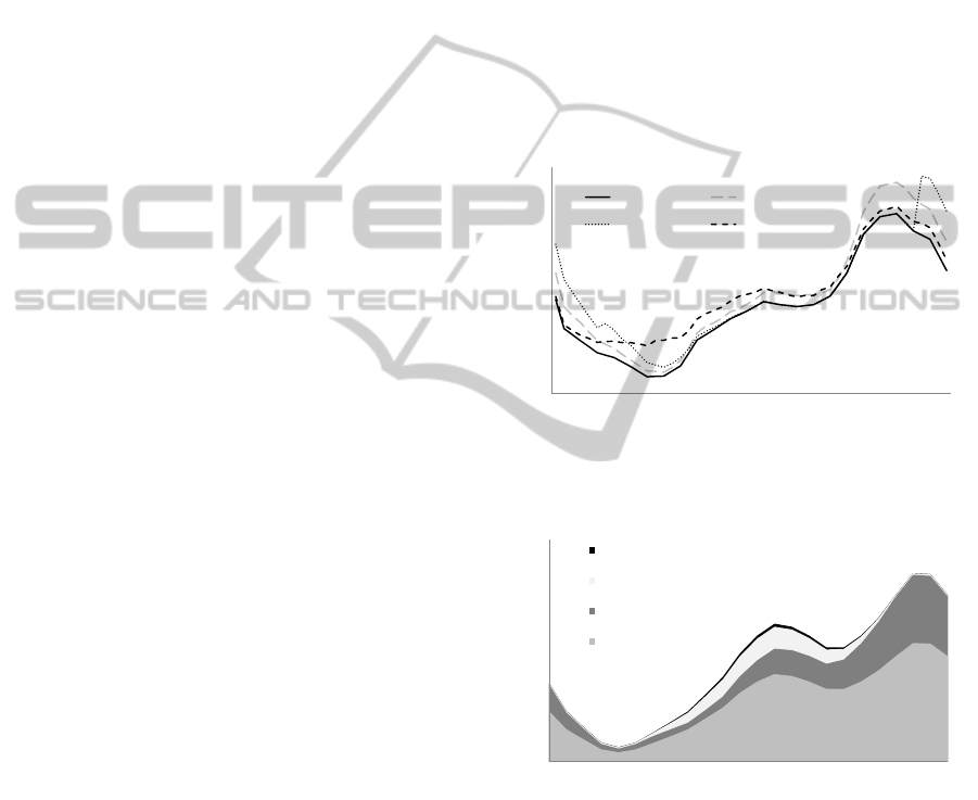
The daily load curve presented in Figure 5
illustrates the consumption pattern for a typical
winter day for the year of 2030 in a LV network
with a 630kVA transformer capacity. In this
scenario this network supplies approximately 63
plugged-in EV. From Figure 5 it is also possible to
compare the impact of the considered charging
strategies on the daily load curve.
As shown, adopting a dumb charging strategy
will increase the peak power approximately 62 kW,
since EV are likely to be charged at the end of the
day. Adopting a multiple tariff scheme will result in
a new peak at 22:00h, when the period with a lower
tariff begins. When adopting a smart charging
strategy, the EV charge occurs preferentially on the
valley hours, contributing to keep the peak load
almost unchanged.
Regarding the contribution of the μG units, in
Figure 6 it is possible to verify that since the
majority of μG units are photovoltaic systems,
during the hours with greater sunlight exposure there
is only a small reduction in the peak power. It is
important to state that Figure 6 is referred to the
scenarios b), where only the μG was considered.
Figure 5: 2030 load diagram at the MV/LV substation of a
LV network with 630 kVA transformer adopting different
charging strategies.
Figure 6: 2030 load diagram at the MV/LV substation of a
LV network with 630 kVA transformer for the different
scenarios of μG.
The evaluation of the branches overloading is
also an important measurement of the adequacy of
the Portuguese networks for future deployment of
EV. In general, the branches’ congestion levels
increase in the scenarios without direct control of the
EV charging.
Figure 7 shows an example obtained for a LV
network with a 400kVA MV/LV transformer. The
0
50
100
150
200
250
300
350
400
450
048121620
Power (kW)
Without EV Dumb Charging
Multi-tariff Smart Charging
Time
0
50
100
150
200
250
300
350
400
450
1357911131517192123
Power(kW)
Time
2030‐CEN0
2030‐CEN1
2030‐CEN4
2008
2030
–
noµG
2030
–
µG scenarioA
2030
–
µG scenarioB
2008
SMARTGRIDSWITHELECTRICVEHICLES:THEINITIALFINDINGSOFPROJECTREIVE-AProjectFundedby
thePortugueseMinistryofEconomy,InnovationandDevelopment
45

figures provide a comparison of branches loading in
the peak hour of the scenarios without EV (upper-
left picture) and with 14 EV, in order to provide a
general overview of the three charging methods’
impacts in this matter. In this case the maximum
branch loading detected increased 45% with the
dumb charging, 56% with the dual tariff and only
11% with the smart charging.
Adopting different charging strategies is also
expected to increase the networks active power
losses, since the power consumption increases.
As shown before, uncontrolled charging
strategies increase the peak power consumption,
increasing also the current and consequently the
active power losses. However, controlling the EV
load though smart charging strategies,
complemented by local generation from the µG
units, contributes to avoid significant increases in
the network losses. The value of energy losses in the
Portuguese distribution network (MV and LV) was
1782 GWh in the year 2008. This value represents
approximately 4.14% of the total consumption in the
entire Portuguese distribution network.
From the results obtained due to conventional
load growth, in 2030, energy losses will reach the
value of 4394 GWh. When considering the future
deployment of EV, losses could reach 5209 GWh if
EV charging is not controlled. In this case, the
integration of μG could reduce losses to 4698 GWh
in scenario A and to 4457 GWh in scenario B. This
value can be further reduced if the smart charging is
adopted, as shown in Figure 8.
As expected, the smart charging provides better
results since it makes the load distribution along the
day more uniform, consequently reducing the grid’s
peak demand.
a) Without EV
b) Dumb Charging
c) Multiple tariff scheme
d) Smart charging
Figure 7: Lines loading for a LV network with a 400 kVA transformer (low EV scenario, Summer day, without μG and for
the year 2030). Grading between light grey and black, stand for increasing values of congestion, from 0 to 100%.
SMARTGREENS2012-1stInternationalConferenceonSmartGridsandGreenITSystems
46

Figure 8: Total distribution network losses (MV and LV)
for 2020 and 2030, High EV integration scenarios.
From the results obtained it was also possible to
conclude that the µG and controlled EV charging
also have a positive impact in the CO2 emissions
and voltage profiles. When comparing the EV
charging schemes (µG not considered), the results
obtained show that the the smart charging can avoid
~110 ktons of CO2emissions when compared to the
dumb charging. The μG, in turn, can avoid 70 ktons
when comparing Scenario B with the case without
μG (EV not considered). Contrary to the EV
charging strategy adopted, the μG has little influence
in the grids’ voltage profiles. Although not presented
in the paper, the results obtained showed that the
smart charging can avoid possible voltage violations
that are likely to occur if other charging schemes are
adopted.
4 SMART GRID IN
LABORATORIAL
ENVIRONMENT
As previously stated, the REIVE project aims the
conceptualization of innovative control and
management algorithms for smart grid applications,
where EV and micro-generation units present one of
the most relevant roles. Additionally, the smart grid
paradigm is necessarily supported by an adequate
communication infrastructure, which will
conditioned the possibility of developing more or
less ambitious control and management schemes.
Additionally, the deployment of EV and micro
generation units in distribution grids introduce
important impacts in terms of voltage profiles and
branches congestion levels, thus requiring specific
systems allowing interaction with these elements in
order to control and manage their power
interchanges with the grid. Therefore, the
laboratorial infrastructure under development is the
physical space that will enable pre-prototyping new
power electronic interfaces for EV and micro
generation units, which incorporate the capability of
active interaction with the smart grid control
infrastructure. The laboratorial infrastructure will
allow the individual and integrated testing
procedures for new concepts, control algorithms to
be housed at the different smart grid hierarchical
layers, communication architectures, technologies
and protocols that will allow feasibility
demonstration regarding functional and technical
specifications developed within the project. In this
sense, the main objectives of the REIVE laboratorial
infrastructure are:
1) Development of applied research activities
regarding the development of the microgrid
concept as the base power system active cell for
smart grids.
2) Development of advanced research activities
regarding active integration of EV in the smart
distribution grid control architecture.
3) Consolidation key competences regarding the
natural moving from the actual distribution grid
operational paradigm to a more active one,
where the smart grid concept is fully
envisioned.
4) Development of software modules for pre-
prototypes of the smart grid key controllers for
its different operational layers (such as MGCC,
SSC, etc) and perform a preliminary evaluation
of its performance in close collaboration with
simulation results
5) Development of pre-prototypes of advanced
interfaces for EV and micro-generation units, in
accordance with the project on-going functional
and technical specifications.
6) Actively support national and international
standardization activities in different domains,
according to the laboratorial developments
obtained in the project
7) Technology transfer to the industry regarding
innovative concepts for smart grid controllers
and for EV and microgeneration interfaces
under development within the project.
5 CONCLUSIONS
The REIVE project is dedicated to develop and test
technical solutions and pre-industrial prototypes for
the active and intelligent management of electricity
grids with large scale integration of μG and EV.
0
1000
2000
3000
4000
5000
6000
Without μG Scenario A Scenario B Without μG Scenario A Scenario B
2020 2030
Losses (GWh)
Without EV Dumb Ch arg ing Multiple Tariff Smart Ch arging
SMARTGRIDSWITHELECTRICVEHICLES:THEINITIALFINDINGSOFPROJECTREIVE-AProjectFundedby
thePortugueseMinistryofEconomy,InnovationandDevelopment
47

Within the framework of this project, innovative
tools were developed to identify the impacts of the
μG and of the different strategies adopted for the
management and control of EV. The steady-state
results presented proved that µG and EV integration
might bring important technical benefits to
distribution grids, namely if the EV deployment is
accompanied with the implementation of controlled
EV charging schemes. The major benefits are related
with the reduction of branches overloading, grids’
peak power, energy losses and CO
2
emissions.
The future work of this project is focused on the
development of laboratorial prototypes of the
software modules that will constitute the EB2, EB3,
DTC and SSC controllers, together with the required
interfaces in order to interact with the devices
installed in the field (loads, EV, μG, storage
devices). The usage of laboratorial facilities will
allow extensive validation of the developed concepts
and control strategies for facilitating μG and EV
integration.
ACKNOWLEDGEMENTS
This work was supported in part by Fundo de Apoio
à Inovação (Ministério da Economia, da Inovação e
do Desenvolvimento), within the framework of the
Project REIVE – Redes Eléctricas Inteligentes com
Veículos Eléctricos, and by Fundação para a Ciência
e Tecnologia under Grants SFRH/BD/48491/2008
and SFRH/BD/47973/2008 and within the
framework of the Project Microgrids+EV:
Identification of Control and Management Strategies
for Microgrids with Plugged-in Electric Vehicles –
ref. PTDC/EEA-EEL/103546/2008.
REFERENCES
Barbeiro, P. N. P., Moreira, C. L., Soares, F. J. &
Almeida, P. M. R. Year. Evaluation Of The Impact Of
Large Scale Integration Of Micro-Generation Units In
Low And Medium Voltage Distribution Networks. In:
Innovative Technologies For An Efficient And
Reliable Electricity Supply (Citres), 2010 Ieee
Conference On, 2010.
Callaway, D. S. & Hiskens, I. A. 2011. Achieving
Controllability Of Electric Loads. Proceedings Of The
Ieee, 99, 184-199.
Clement-Nyns, K., Haesen, E. & Driesen, J. 2010. The
Impact Of Charging Plug-In Hybrid Electric Vehicles
On A Residential Distribution Grid. Power Systems,
Ieee Transactions On, 25, 371-380.
Galus, M. D., Zima, M. & Andersson, G. 2010. On
Integration Of Plug-In Hybrid Electric Vehicles Into
Existing Power System Structures. Energy Policy, 38,
6736-6745.
Gil, N. J. & Lopes, J. A. P. Year. Hierarchical Frequency
Control Scheme For Islanded Multi-Microgrids
Operation. In: Power Tech, 2007 Ieee Lausanne, 1-5
July 2007 2007. 473-478.
Giordano, V., Gangale, F., Fulli, G. & Jiménez, M. S.
2011. Smart Grid Projects In Europe: Lessons Learned
And Current Developments. Joint Research Centre
Institute For Energy.
Lopes, J. A. P., Moreira, C. L. & Madureira, A. G. 2006.
Defining Control Strategies For Microgrids Islanded
Operation. Power Systems, Ieee Transactions On, 21,
916-924.
Lopes, J. A. P., Rocha Almeida, P. M. & Soares, F. J.
Year. Using Vehicle-To-Grid To Maximize The
Integration Of Intermittent Renewable Energy
Resources In Islanded Electric Grids. In: Clean
Electrical Power, 2009 International Conference On,
9-11 June 2009 2009. 290-295.
Lopes, J. A. P., Soares, F. J. & Almeida, P. M. R. 2011.
Integration Of Electric Vehicles In The Electric Power
System. Proceedings Of The Ieee, 99, 168-183.
Messias, A. A. 2009. The Inovgrid Project: Distribution
Network Evolution As A Decisive Answer To The
New Challenges In The Electrical Sector. Edp
Distribuição.
Rosa, M., Issicaba, D., Gil, N., Soares, F. J., Almeida, P.
M. R., Moreira, C., Ribeiro, P., Heleno, M., Ferreira,
R., Sumaili, J., Meirinhos, J., Seca, L., Lopes, J. A. P.,
Matos, M., Soultanis, N., Anestis, A., Karfopoulos, E.,
Mu, Y., Wu, J., Ekanayake, J. & Narayana, M. 2011.
Functional Specification For Tools To Assess Steady
State And Dynamic Behaviour Impacts, Impact On
Electricity Markets And Impact Of High Penetration
Of Ev On The Reserve Levels. Deliverable D2.2 Of
The European Project Merge, .
Xu, Z., Ostergaard, J. & Togeby, M. 2010. Demand As
Frequency Controlled Reserve. Power Systems, Ieee
Transactions On, Pp, 1-10.
SMARTGREENS2012-1stInternationalConferenceonSmartGridsandGreenITSystems
48
