
The Improved SSR Electromagnetic Simulation Model
and Its Comparison with Field Measurements
Xiaorong Xie
1
, Yipeng Dong
1
, Kai Bai
2
, Xun Gao
3
and Ping Liu
2
1
State Key Lab. of Power System, Department of Electrical Engineering, Tsinghua University, Beijing 100084, China
2
North China Electric Power Research Institute Co., Ltd, Xicheng District, Beijing 100045, China
3
North China Grid Co., Ltd, Power Dispatch Center, Xicheng District, Beijing 100053, China
Keywords: Subsynchronous Resonance, Electromagnetic Simulation, Series Compensation.
Abstract: Electromagnetic simulation (EMS) plays an important role in the evaluation of subsynchronous resonance
(SSR). To meet the requirement of practical engineering, this paper discusses how to improve the modeling
method of SSR-EMS in three important aspects, i.e., the shaft system of turbine generator, the series
compensation and the supplementary excitation damping controller (SEDC). Thus a systematically
improved EMS model was put forward, which includes a lumped mass-spring model with adjustable and
non-linear mechanical damping, a series compensation model incorporating MOV with the gap protection
logic and an engineering model of SEDC to reflect the dynamics of the power-electronic exciter. The
developed model overcomes the shortage of the traditional one and is applicable to the accurate analysis on
SSR stability, transient torque and fatigue expenditure when the system experiences large disturbances. The
proposed method is then used for the simulation of a real SSR event caused by a short-circuit fault in the
Shangdu series-compensated power system. The simulation results are compared with the field
measurements and a good consistence is found. Consequently, the improved EMS model is proved to be
applicable, accurate and effective for SSR analysis in practical engineering.
1 INTRODUCTION
With the wide application of series compensation in
power systems, the SSR issue attracts more and
more attentions (SSR W.G., 1992). SSR analysis
plays an important role in evaluating its risks and
selecting countermeasures. Currently, such methods
as frequency-scanning, complex torque coefficient,
eigenvalue analysis and electromagnetic simulation
(EMS) are widely applied (Yu et al., 2006; Canay,
1982; Hara et al., 1994). Among these methods, the
time-domain EMS, despite of its complicated
modeling and heavy computation, possesses obvious
advantages as follows:
1) Capable of modeling system nonlinearities;
2) Applicable to the analysis of multi-mode
torsional oscillation in multi-machine systems;
3) Able to analyze either large or small
disturbances, and to provide dynamic response and
output in the sense of electromagnetic transients;
4) Suitable for the evaluation of various
SSR-damping devices, such as the supplementary
excitation damping control (SEDC).
Therefore, EMS becomes an indispensible tool
for SSR analysis in engineering application.
Currently, this analysis method is mainly depend on
commercial software like PSCAD/EMTDC
(Kajoijilertsakul et al., 2011), which can provide the
basic models and numerical method required by
SSR analysis and meet the general analysis demand.
However, there are some problems requiring
attention and improvement. To meet the requirement
of practical engineering, this paper mainly focuses
on the modeling improvement in three aspects:
1) The mechanical damping of the T-G shaft
system, assumed in many studies to be a fixed value,
should be modeled as a function of the T-G’s
working condition (Xie and Zhang et al., 2011).
2) The nonlinearities of the metal oxide varistor
(MOV), the gap and other protective devices should
be incorporated for accurate modeling of a
real-world series compensation.
3) The power-electronic circuit of the excitation
system is regarded as an “instantly” established
circuit during electromechanical transients. However,
there is a time-delay, which will affect the dynamics
419
Xie X., Dong Y., Bai K., Gao X. and Liu P..
The Improved SSR Electromagnetic Simulation Model and Its Comparison with Field Measurements.
DOI: 10.5220/0003973704190424
In Proceedings of the 2nd International Conference on Simulation and Modeling Methodologies, Technologies and Applications (SIMULTECH-2012),
pages 419-424
ISBN: 978-989-8565-20-4
Copyright
c
2012 SCITEPRESS (Science and Technology Publications, Lda.)
of exciter-based SEDC control system, thus making
it necessary to refine its modeling.
This paper attaches great emphasis on the
modeling improvement in the mentioned aspects,
and applies it in a real electric network, i.e., the
Shangdu series-compensated power system. Then,
EMS results are compared with the actually
recorded data to prove its accuracy, applicability and
efficiency of the improved simulation method.
2 THE IMPROVED MASS-
SPRING SHAFT MODEL OF
THE TURBINE-GENERATOR
For SSR evaluation, a turbine-generator (T-G) is
represented as a lumped mass-spring model (IEEE
Committee report, 1977, 1985; Baker et al., 2005).
For instance, the widely used 600MW T-G in China
is expressed by a 4-mass spring model, as in Figure
1. It has 4 rotors, i.e., a high-and-
intermediate-pressure turbine (HIP), two low-
pressure turbines (LPA/LPB), and a generator rotor.
Figure 1: The lumped T-G shaft system.
Representing the T-G as inertias connected by
shafts of appropriate stiffness, the dynamic equation
for the spring-mass system may be written as (1)
me
Mδ Dδ Kδ TT
(1)
Where:
δ
is the torsional angle displacements
column matrix;
M
is a diagonal matrix
representing the inertias of masses;
D
is the
damping coefficient matrix;
K
is a tri-diagonal
matrix of torsional stiffness;
m
T
,
e
T
are vectors of
mechanical and electrical torques respectively.
Model (1) is widely adopted in EMS softwares
like PSCAD/EMTDC. However, it has several
drawbacks in practice: The damping matrix
D
can
neither be provided by the manufacturer nor be
measured through test directly. Actually it is a
nonlinear function of system condition and cannot
be interpreted by model (1). But in PSCAD/EMTDC,
its value can only be set fixed rather than
self-adjustable. As a result, when operating status
changes, it is impossible to achieve accurate EMS.
Model (1) is improved in view of these
shortages. Specifically, implement model
decoupling transformation to model (1). That is,
have
m
δ Qδ
, and have equation (1) left multiplied
by
T
Q
, where the model decoupling matrix
Q
is
the right eigenvector of
-1
MK
. Then, model (1)
can be transformed into the canonical form as (2):
m m m m m m m
M δ D δ K δ T
(2)
Where
m
δ Qδ
,
T
m m e
= ( )T Q T T
,
T
m
M Q MQ
,
T
m
K Q KQ
,
T
m
D Q DQ
.
In model (2), although the coefficient matrices
m
M
and
m
K
are decoupled into diagonal
matrices, it is still impossible for the damping
coefficient matrix
m
D
to achieve complete
decoupling since it is not a diagonal matrix.
However, as the coupling damping between modes
is usually assumed to be small and can be almost
contained within the damping of each mode, the
non-diagonal elements of
m
D
are ignored. This
means to have
m md 1 2 3
diag , , , 0
m m m
d d dDD
(where 0 represents the damping of
electromechanical mode), thus realizing the
decoupling among torsional modes. So each natural
mode is governed by an equation of the form:
m mm m m m m m
, 1,...,
k k k k k k k
M d K T k N
(3)
where the subscript
k
denotes each of the
decoupled torsional modes.
Compared with model (1), model (3) is
advantageous in achieving decoupling of torsional
mode, and replacing the complicated
m
D
with
modal damping
m
d
, which can be measurable via
various methods, e.g., the excitation-injection test
and the system-side disturbance test. Furthermore, it
is possible to set
m
d
as a nonlinear function of
generator variables and to simulate its actual
variation with the constantly changing system
conditions in EMS. According to our actual
measurements, the modal mechanical damping can
be expressed by the non-linear function:
m0 m
m m0 m
m0
ed k P c
(4)
Where
m
is the modal speed deviation,
P
is
the power of the unit, and
m0 m0 m
m0
, , , kc
are
coefficients, which can be determined with a method
like that proposed in literatures (Xie and Zhang et al.,
2011).
SIMULTECH 2012 - 2nd International Conference on Simulation and Modeling Methodologies, Technologies and
Applications
420
3 THE IMPROVED MODEL OF
SERIES COMPENSATION
The fixed series compensation (FSC), as shown in
Figure 1, consists of series capacitor banks and
corresponding protection devices such as MOV,
current-limiting damping elements, protective gap
and by-pass switch. MOV and the protective gap,
though exert no impact on SSR stability during
small disturbances, have significant impact on the
transient torque, especially during the fault
occurrence and a period of time after the fault.
Therefore, it is necessary for EMS to take the
nonlinear characteristics of MOV, the protective
gap and the by-pass switch into account,
especially when there’s a need to analyze the
transient torque and the consequent fatigue
expenditure of the generator shaft following large
disturbances. Figure 3 is the improved modelling
of FSC in our EMS method, among which:
1) MOV is expressed by the series circuit
composed of controllable voltage source and
non-linear resistance. Its V-I characteristic is
described with an external file.
2) The protective gap and the by-pass switch
are replaced by an ideal switch with specific logic
of protection to simulate MOV’s various
protective actions: a delayed monostable trigger
signal is output when the current or the energy of
MOV exceeds the set value, and thus the switch
for controlling the ideal by-pass is turned on for a
set time period and then turned off again.
The FSC model in Figure 2 is able to simulate
the general actual logic of the practical series
capacitor as well as its protective circuit when
experiencing large disturbances. Since the energy
exchange between the series capacitor and the
generator determines the SSR dynamic, especially
the transient torque of the shaft, this model can
accurately reflect the actual dynamics of FSC.
Figure 2: Schematic of FSC.
Figure 3: Electromagnetic model of FSC.
4 THE ELECTROMAGNETIC
MODEL OF SEDC
SEDC is a real-time control system that works
through the excitation system by modulating the
field voltage at torsional frequencies. Figure 4
illustrates the relationship of the SEDC (Xie and
Guo et al., 2011), the excitation regulator, the
generators and the grid. As a supplementary control,
SEDC uses the mechanical speed of the HIP turbine
(
1
) to generate the subsynchronous control output
(
SEDC
u
). However, the well-established
electromechanical transient model of the
excitation system cannot be applied directly in
SSR-EMS, because the control frequency (300Hz)
of the thyristor in the power-electronic circuit, i.e.,
the three-phase fully-bridge controlled rectifier
bridge, is much higher than that of DC and
low-frequency components, on which the
electromechanical transient analysis focuses. In
other words, it is reasonable to ignore the
dynamics of the power-electronic circuit in
electromechanic analysis and regard it as an ideal
“algebraic” converter. But in SSR-EMS, the
dynamic characteristics of the power-electronic
exciter must be considered because the torsional
frequencies (generally from 10 to 40Hz) and the
control frequency of thyristor are comparable.
Based on tests on the exciters of large generators,
a refined EMS model of the excitation system with
SEDC is proposed, as shown in Figure 4, in which,
the power-electronic circuit of the exciter is
expressed by a first-order-plus-time-delay transfer
function. The dead time delay (
d
T
) represents the
computational delay of the control law and the
transport delay of the thyristor, while the first-order
function is used to approximate the dynamics of the
power-electronic circuit. Although
,
dr
TT
, generally
from several to a dozen milliseconds, are very
The Improved SSR Electromagnetic Simulation Model and Its Comparison with Field Measurements
421
small compared with electromechanical transients,
they are comparable with the period of torsional
modes and thus have significant impact on the
tuning of SEDC parameters.
d
1
TS
e
Ts
GEN
AVR/PSS
U
t
,
4
, P
e
1
SEDC
u
SEDC
E
fd
Figure 4: EMS model of the SEDC and excitation system.
5 VERIFICATION OF THE
IMPROVED MODEL
The improved EMS model proposed above has been
applied in many practical SSR studies. Here a
short-circuit fault that occurred in a real system is
used to verify its effectiveness.
5.1 The Shangdu System
Shangdu Power Plant (SPP) is located in Inner
Mongolia Autonomous Region, about 300km north
of Beijing. It has four 600MW turbine-generators
connected to North China Power Grid through 500
kV lines, as shown in Figure 5. To improve transfer
capability and system stability, FSCs are applied to
the two lines between SPP and Chengde substation
with 45% compensation degree. Each turbine-
generator consists of four rotors, as shown in Figure
1, resulting in three torsional modes, of which the
frequencies (in Hz) are listed in Table 1. Previous
study indicated that the generator suffered serious
SSR if one of the two Shangdu-Chengde lines is
switched off for any reason (Xie and Guo et al.,
2011). Thus SEDC and torsional stress relay (TSR)
were developed to solve the problem. SEDCs, TSRs
and FSCs were put into practical operation in 2007.
Figure 5: The one-line diagram of the Shangdu system.
5.2 Parameters of the Improved
Models
1) The turbine-generator shaft
The torsional frequencies of the four generators
are shown in Table 1. The typical coefficients of the
mechanical damping model (3) were obtained with
field-test data and listed in Table 2. To save place,
other shaft model parameter won’t be listed here.
Table 1: Modal Frequencies of the Shangdu T-Gs.
Gen.#
mode #1
mode #2
mode #3
1
15.33
26.12
30.54
2
15.32
26.12
30.52
3
15.22
26.04
30.51
4
15.19
26.01
30.25
Table 2: Coefficients of the mechanical damping model.
Mode #
m
m
m
c
m
k
1
0.010
25.2
0.005
0.135
2
0.007
31.0
0.006
0.135
3
0.005
20.0
0.012
0.180
2) The excitation system with SEDC
The standard IEEE ST4B AVR and IEEE PSS2B
PSS models (Kamwa et al., 2005) are modified to
represent the excitation system with SEDC included,
of which the critical time constants are measured
through filed tests, i.e.,
8.0 ms, 4.0 ms
dr
TT
.
3) MOV and the protective gap
MOV has three types of protection, as shown in
Table 3. Once MOV protection is triggered, the gap
is controlled to spark within 2 ms and then
capacitors are bypassed for a time period (generally
3 seconds) or until the fault is completely cleared.
Table 3: The settings of MOV and the protective gap.
MOV protection
Settings
Actions
Over-current
12 kApeak
Gap spark and
single-phase bypassed
Excess-energy
bypass
22 MJ
Gap spark and
single-phase bypassed
Excess-energy
bypass without
reclosing
26 MJ
Gap spark, 3-phase
bypassed with the
recloser locked
5.3 The Short-circuit Fault
On August 8, 2010, the system operated normally
before the fault. At 20:16:58, a phase-to-ground
fault happened on phase-A due to a lightning strike
on Line II at 88km from Shangdu. The faulted line
was tripped from Chengde and Shangdu sides after
55 and 63 milliseconds respectively. The recloser at
Shangdu side reclosed successfully. However, the
recloser at Chengde side failed and then phases B
and C were tripped off about 89 milliseconds after
the fault. Consequently, Line II was disconnected at
SIMULTECH 2012 - 2nd International Conference on Simulation and Modeling Methodologies, Technologies and
Applications
422
Chengde side. Divergent SSR appeared at Units #1
and #2. TSR then tripped Unit #1 about 3.546
seconds following the fault. Thus SSR converged
rapidly. However, 6.388 seconds later, Unit #2 was
tripped by its TSR because the accumulated fatigue
loss-of-life exceeded its setting values. During the
process, the shaft speed data were recorded.
5.4 Actual Measurements Vs.
Simulations
A specific analysis on the above-mentioned fault
was carried out with the improved SSR-EMS model.
The simulation results are compared with actual
measurements, as illustrated in Figures 6-9, in which
the modal speeds of each generator as well as its
corresponding upper envelope are plotted. It can be
obviously observed that the actual measurements are
basically in accordance with the simulated curves.
Of course, there are some inconsistent “burs” on the
upper envelopes for actual measurement due to
noises in the obtained signals.
Figure 6: Measured vs. simulated SSR dynamics (unit #1).
Figure 7: Measured vs. simulated SSR dynamics (unit #2).
Figure 8: Measured vs. simulated SSR dynamics (unit #3).
The Improved SSR Electromagnetic Simulation Model and Its Comparison with Field Measurements
423
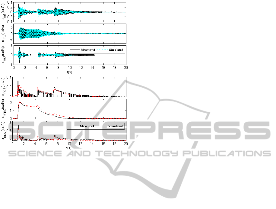
Figure 9: Measured vs. simulated SSR dynamics (unit #4).
6 CONCLUSIONS
Electromagnetic simulation is critical to SSR
analysis and control-design. This paper presents
several improvements in the modeling of SSR-EMS:
i) the lumped mass-spring model with adjustable and
nonlinear mechanical damping to simulate the
variation of mechanical damping under different
operating conditions and system disturbances; ii) a
series compensation model incorporating MOV and
the gap protection logic for accurate modeling of
practical FSC when confronted with serious faults;
iii) an EMS model of SEDC to reflect the dynamics
of the power-electronic exciter. To verify the
effectiveness, the improved model is used to analyze
a short-circuit fault that occurred in a real system,
i.e., the Shangdu series-compensated power system.
The simulation results are compared with the field
measurements and a good consistency is discovered.
ACKNOWLEDGEMENTS
This work is supported by National Natural Science
Foundation of China (51077080 and 51037002) and
State Key Lab. of Power System (SKLD11M02).
REFERENCES
SSR W.G. (1992). Reader’s guide to subsynchronous
resonance. IEEE Trans. on Power Systems, 7(1),
150-157.
Yu, C., Cai, Z., Ni, Y., et al. (2006). Generalized
eigenvalue and complex torque coefficient analysis for
SSR study based on LDAE model.IEE Proc. Gener.
Transm. Distrib, 150(1), 25-34.
Canay I. M. (1982). A novel approach to the torsional
interaction and electrical damping of the synchronous
machine Part I: Theory. IEEE Trans. on Power
Apparatus and Systems, 101(10): 3630-3638.
Hara, T., Kobayashi, N., Takei, A., et al. (1994).
Development of a damping analysis program for
multi-generator power systems . IEEE Trans. on
Power Systems, 9(4), 1803-1810.
Kajoijilertsakul, P., Asawasripongtorn, S., Sanposh, P., et
al. (2011). Modeling and simulation of 500 kV
transmission network for numerical fault calculation,
detection using PSCAD/EMTDC. In APPEEC, 2011
Asia-Pacific Power and Energy Engineering
Conference, 1- 4.
Xie X., Zhang X., Dong X., et al. (2011). Nonlinearity of
torsional damping and its effect on SSR characteristics
of turbine generators. In GIGRE Colloquium on New
Development of Rotating Electrical Machines,
163-170.
IEEE Committee. (1977). First benchmark model for
computer simulation of subsynchronous resonance.
IEEE Trans. on Power Apparatus and Systems, 96(1),
1565-1572.
IEEE Committee. (1985). Second benchmark model for
computer simulation of subsynchronous resonance.
IEEE Trans. on Power Apparatus and Systems,
104(5), 1057-1066.
Baker, D. H., Boukarim, G. E., D'Aquila, R. (2005).
Subsynchronous resonance studies and mitigation
methods for series capacitor applications. In PES
2005, PES Inaugural Conference and Exposition in
Africa, 386-392.
Xie X., Guo X., Han Y. (2011). Mitigation of
multimodal SSR using SEDC in the Shangdu
series-compensated power system. IEEE Trans. Power
Systems, 26(1), 384-391.
Kamwa, I., Grondin, R., Trudel G. (2005). IEEE PSS2B
versus PSS4B: the limits of performance of modern
power system stabilizers. IEEE Trans. on Power
Systems, 20(2), 903-915.
SIMULTECH 2012 - 2nd International Conference on Simulation and Modeling Methodologies, Technologies and
Applications
424
