
SUPERCONDUCTING MAGNETIC ENERGY STORAGE
A Technological Contribute to Smart Grid Concept Implementation
Nuno Amaro
1
, João Murta Pina
1
, João Martins
1
and José Maria Ceballos
2
1
Center of Technology and Systems, Faculdade de Ciências e Tecnologia, Universidade Nova de Lisboa,
Monte de Caparica, 2829-516, Caparica, Portugal
2
"Benito Mahedero" Group of Electrical Applications of Superconductors, Escuela de Ingenierías Industriales,
University of Extremadura, Avenida de Elvas s/n, 06006, Badajoz, Spain
Keywords: Smart Grid, SMES, Superconducting Devices.
Abstract: The urgent need to solve existing problems in the electric grid led to the emergence of the new Smart Grid
(SG) concept. A smart grid is usually described as an electricity network that can intelligently integrate the
actions of all players connected to it in order to efficiently deliver sustainable, economic and secure
electricity supplies. Smart grids should be flexible, accessible, reliable and economic, bringing great new
challenges into grid management. In order to implement this concept it is necessary to consider the
operation of several new devices in the electrical grid. A class of these potential devices is Superconducting
Magnetic Energy Storage (SMES) that present, among other features, very fast response times. SMES
devices can play a key role in helping to overcome several grids’ faults. In this paper it is described the
possibility to integrate SMES into SG, and the advantages of this integration.
1 INTRODUCTION
Nowadays electric power producers must obey
several laws that, among other things, force them to
produce from a distinct mix of sources, reduce their
carbon emissions and assure an adequate response to
power demand. These aspects reveal the necessity to
modernize the electric grid. Currently, only one third
of the potential energy contained in the several
existing thermal sources is successfully transformed
into electricity and about 8% of this total electricity
is lost, only in the transmission lines (Farhangi
2010). An obvious conclusion is drawn: the existing
electric grids are inefficient.
Besides this, the increasing number of human
population results in an increasing electricity
demand. In 2020, it is estimated that the
consumption of electricity will surpass 27,000 TWh.
When compared to the consumption of the year
2000 (15,400 TWh) this means a 75% increase
(Garrity 2008). This increasing demand accentuates
existing issues in an electric grid. These are
commonly accepted to include, amongst others
(Benysek, 2007):
Voltage dips and swells.
Frequency oscillations and harmonic issues.
Phase unbalancing.
Hierarchical grid (failure of one element can
lead to a major failure of the grid).
Today it is believed that the answer to these
issues is based upon a fundamental concept: Smart
Grids (SG).
The future electric grid must then be provided
with intelligence, having several fundamental
features: ability to remotely monitor and control the
grid elements and self-healing capability to
automatically overcome faults (F. Li et al. 2010).
This creates a tremendous challenge, because in
order to assure these characteristics several
devices/protocols are needed, as well as a huge
standardization effort (Gungor et al. 2011), amongst
other complex aspects. Many of these
devices/protocols already exist and just need to be
applied to SG. One such technology with potential
application are superconducting devices, as
superconducting magnetic energy storage (SMES)
and superconducting fault current limiters (SFCL)
(Hassenzahl et al. 2004; Hassenzahl 2001;
Malozemoff et al. 2002). The integration of these
two devices into SG is desirable because these
devices can address several of the existing issues in
electric grids. Throughout this document it will be
113
Amaro N., Murta Pina J., Martins J. and Maria Ceballos J..
SUPERCONDUCTING MAGNETIC ENERGY STORAGE - A Technological Contribute to Smart Grid Concept Implementation.
DOI: 10.5220/0003978301130120
In Proceedings of the 1st International Conference on Smart Grids and Green IT Systems (SMARTGREENS-2012), pages 113-120
ISBN: 978-989-8565-09-9
Copyright
c
2012 SCITEPRESS (Science and Technology Publications, Lda.)
discussed the advantages in integrating SMES
systems in a SG, and also, although briefly, the
advantages of SFCL.
2 SMART GRIDS – SHORT
OVERVIEW
2.1 Current Research Projects
The need to transform the existing electric grid in a
SG has originated a large number of research efforts,
in order to assure the quality of the future electric
grids.
European Union created in 2005 the SmartGrids
European Technology Platform with representatives
from industry, production and transmission
companies, researchers and regulators, to generate
objectives and tasks with the main purpose of
obtaining a common vision about electric grid in
Europe, after the year 2020 (Comission, E., 2005;
Comission, E., n.d.).
In USA several initiatives arise in parallel, in
order to study the electric grids of the future, and
how to perform the transition for those grids. Among
these initiatives, highlight the following: IntelliGrid
(EPRI, n.d.), which already achieved important
results (Hutson et al. 2008; McGranaghan et al.
2008); Grid Wise (Cherian & Ambrosio 2004),
created by the Department of Energy; Modern Grid
Initiative (Pullins 2007), from the National Energy
Technology Laboratory; and Distribution Vision
2010 (Fanning & Huber 2005), a consortium of 6
companies aiming to develop mechanisms and
devices to apply in SG.
All these initiatives have the common goal of
develop intelligent electric grids. However one of
their greatest challenges is how to implement the
transition from the existing electric grid to a SG, as
the former cannot be simply disconnected.
Furthermore, during several years, it will be
necessary to assure the coexistence of the two types
of grids in harmony. It is still necessary to answer to
this challenge, and current research lines have
already focused their attention on these issues.
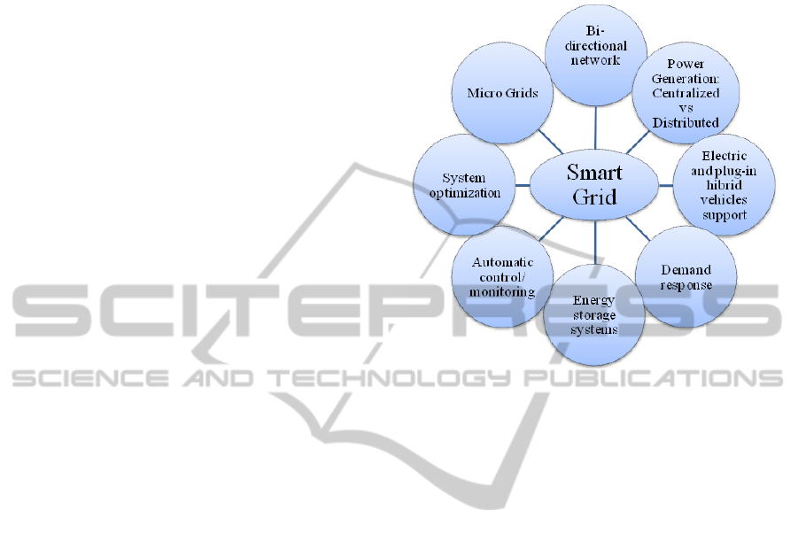
2.2 Smart Grids Main Features
Considering the common goals of the several
research groups presented in the previous section,
the Smart Grid must address the features presented
in figure 1.
The characteristics outlined in figure 1 are
essential to the success of SG. Existing electric grids
are mainly unidirectional. To allow a full control
over the grid, both information and energy must
flow in a bidirectional way.
Figure 1: Main characteristics of a Smart Grid.
With the increasing production of electric energy
from renewable sources like sun and wind, electric
grids face a new challenge: the intermittence of
these resources. Along the next years, the
penetration of these resources in the electric grid
will increase, which creates several additional issues
that need to be solved. Those issues can be of
various types, and be present in distinct grid
segments (Ipakchi & Albuyeh 2009):
Transmission grid: superconducting wind
generators up to 10 MW are currently foreseen for
offshore applications (Abrahamsen et al. 2010).
Wind farms with such an amount of intermittent
power raise stability restrictions.
Distribution grid: together with huge wind
farms projects (high power capacity) there is an
increasing number of distributed generators (DG) as
small wind farms and photovoltaic plants, with low
power production. The intermittence of solar and
wind resources, along with the increasing
penetration of these small power plants brings out
the need to carefully control all the existing elements
in a grid (including spinning reserve elements), and
to minimize local impacts (voltage sags and
frequency oscillations) that can spread to other
adjacent grids. The electric grid can accommodate
medium and low voltage distributed energy
resources, called Microgrids (MG) (Hatziargyriou et
al. 2007). Each MG cannot only have the capacity to
locally produce electricity, but also to store it and
SMARTGREENS2012-1stInternationalConferenceonSmartGridsandGreenITSystems
114

exchange it with the grid.
Interconnection: it is widely accepted that
interconnection standards have to be unified.
Operational Issues: the instability of the solar
and wind generation raises operational issues, as it is
necessary to assure the correct grid operation when
these resources are not producing the expected
amount of electric power. For instance, the abrupt
lost of power from these sources can lead to grid
instability, with consequences as voltage sags or
frequency oscillations.
Electric/plug-in hybrid vehicles: the expected
increasing penetration of those types of vehicles
brings additional problems. Additional grid capacity
may be needed for charging purposes, and the
impact of charging stations in the grid must be taken
into account.
All the previous challenges must be solved,
assuring that SG behaves as expected, always
optimizing grid operation (maximum operational
efficiency and maximum control of power) and
ensuring its sustainability without harming the
environment.
One possible approach for some of the above
issues consists on the integration in the grid of
Energy Storage Systems (ESS). ESS can
accommodate different technologies, in order to
increase its reliability. For example, ESS can
combine batteries, ultra-capacitors and SMES, to
assure a quick and efficient response to a
contingency situation.
Finally, SG must include the central concept of
Demand Response (DR) (Rahimi & Ipakchi 2010).
DR transfers to the users the responsibility to adapt
their consumption profile to the production of the
grid in which they are inserted. It promotes the
stability of the electric grid by minimizing demand
in peak periods. With the liberalization of electricity
markets in several countries and with the DG using
mainly solar panels, small electricity consumers are
now becoming simultaneously producers
(prosumers). This new concept generates a new
challenge, as grid operators cannot know when these
prosumers are injecting energy in the electric grid
and by that decreasing global energy needs. It is
necessary to review the load profile and provide
tools to simulate and monitor the behavior of the
prosumers, in order to assure maximum grid stability
(Grijalva & Tariq 2011; Lampropoulos et al. 2010).
2.3 Smart Grids Control and
Monitoring
Real time monitoring and control of the SG elements
is essential to assure reliable grid operation. This
implies that every element must present data
processing capacity (Massoud Amin & Wollenberg
2005). Implementation of autonomous processing
allows the electric grid to have bidirectional data and
energy flow. However, it brings up several new
issues because it is essential to assure the security of
the data flow, as well as the creating regulatory
entities that must have the capacity to control both
energy and data flows.
The control of a SG also brings some new
challenges regarding the type of controllers to be
developed, considering centralized or decentralized
control units, and the robust integration of these
controllers, allowing them to coordinately overpass
several contingencies that might occur(Arnold
2011).
It is also necessary to clarify the tasks to be
performed by human operators. These can be
divided into three main areas:
Monitoring (the data in the grid).
Analyzing (events, grid access, etc).
Controlling (stability, fault occurrences, etc).
The research in these three areas generated the
concept of Smart Control Centers (Zhang et al.
2010). These centers have a huge processing
capacity to solve the already mentioned issues that
can occur in an electric grid.
One other concept that arises with SG is smart
metering, implemented by the so-called Advanced
Metering Infrastructure (AMI) (Vojdani 2008).
AMI’s introduce new functionalities that can help
both producers and consumers. These functionalities
include, among others, real-time monitoring of
consumptions and tariffs by the consumers, and
pricing differentiation by producers. Since most of
these functionalities are software based, virtually an
unlimited number of different options can be
implemented. Another important functionality is the
possibility of small producers to choose when to sell
the electricity, thus obtaining better prices. The
implementation and integration of these AMI’s is a
great step to evolve to a fully liberalized electricity
market.
2.4 Simulation Tools and Devices
To perform a correct analysis of SG, and to develop
new concepts, it is essential to use simulation tools.
The existing electric grid simulation tools lack
required functionalities to simulate SG environment
(Arritt & Dugan 2011). This means that another
challenge is to adapt these existent tools, or design
new ones, in a way that they can perform proper SG
modeling, real-time simulation and fault simulation.
SUPERCONDUCTINGMAGNETICENERGYSTORAGE-ATechnologicalContributetoSmartGridConcept
Implementation
115
These tools also have to be scalable, robust and user-
friendly.
Although it is essential to have simulation tools
for SG power flow, a SG can only exist with proper
creation/integration of devices allowing coordinated
and reliable behavior. Among those devices,
highlights power electronics based ones, where three
types of concepts are crucial: Flexible AC
Transmission Systems (FACTS), High Voltage Direct
Current (HVDC) and Smart Transformers (Jiang et al.
2006; Hanson et al. 2002; P. Kadurek et al. 2010; Petr
Kadurek et al. 2011). These three technologies are
envisaged to help providing faster dynamic voltage
control and accurate power (active and reactive)
stability control, over the SG. There is a great variety
of systems relevant to FACTS and HVDC, like
Synchronous Static Compensators (STATCOM),
Static Series Synchronous Compensators (SSSC) or
Unified Power Flow Controllers (UPFP). These
power electronics based devices can be combined
with other concepts, potentially maximizing grid
stability effects. These can include, as already
mentioned, superconducting devices like SMES. The
integration of superconducting technologies in SG has
many potential advantages, which are presented in the
next section.
3 SMES – OVERVIEW
Superconducting Magnetic Energy Storage (SMES)
systems store energy in the magnetic field of a
superconducting coil. Considering the inductance
and current flowing in the coil, namely
L and
I
,
then the stored energy,
E , is given by
2
1
2
ELI=
(1)
Initially, SMES systems were built with low
temperature superconductors (LTS, with typical
operating temperature at 4.2 K), either because high
temperature superconductors (HTS, with operating
temperature typically above 40 K) had not yet been
discovered, but mainly because LTS wire
manufacturing process was already mature. The
costs of these LTS SMES were however not viable,
not only due to the SC wire but also due to the price
of the cryogenic system (estimated as 15% of the
total cost of the all system) (Hsu & W.-J. Lee 1993).
The discovery of HTS and the development of
ceramic materials based wires, allowed that costs
associated with cryogenics substantially decreased.
The problem was that the price of HTS wire was
initially one order of magnitude higher than LTS
wire, making HTS SMES systems still economically
unfeasible (Tsukamoto 2005). Nowadays, as the
price of HTS wire is decreasing (especially Y-Ba-
Cu-O coated conductors), there is a all new future
for HTS SMES (Lehner, 2011).
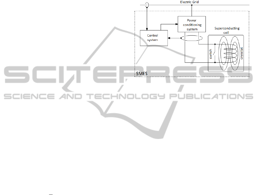
The general scheme of a SMES system is shown
in figure 2.
Figure 2: SMES diagram.
A SMES system is composed by the following
main elements (X D Xue et al. 2006):
Superconducting coil (SC), with a switch
that changes between charging and discharging
mode. The coil must be inside a cryostat that
maintains the required temperature, and there is also
a mechanical structure associated with the coil, in
order to withstand the Lorentz forces developed. The
switch is implemented by a power electronics
converter.
Power conditioning system (PCS), a
bidirectional power electronics interface which
converts electric power from DC to AC, when
charging/discharging the SC coil. The PCS main
component is a Voltage Source Inverter (VSI) or a
Voltage Source Converter (VSC). There are several
topologies that can be used (X D Xue et al. 2006).
Control system (CS), which manages the
exchange of energy between the SMES system and
the grid and also allows grid synchronization. The
most common control strategy is based on pulse
width modulation (PWM) techniques, but other
approaches are possible (Molina & Mercado 2011).
From our point of view, and comparing to other
existing energy storage systems (ESS), SMES
presents two major advantages:
Fast response time (1-5 ms, only limited to
the commutation speed of the PCS components and
the bandwidth of sensors).
High efficiency: including cryogenic
losses the efficiency of SMES system is theoretically
higher than 90%. Other ESS’s have efficiencies
around only 70% (Buckles & Hassenzahl 2000).
SMARTGREENS2012-1stInternationalConferenceonSmartGridsandGreenITSystems
116
These two advantages are only possible because
energy conversion in SMES is purely electrical,
whilst other ESS involve either electrical-chemical
or electrical-mechanical energy conversion.
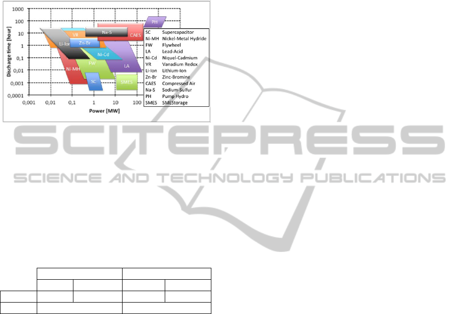
Figure 3 contain a comparison of discharge time
and power ratings for several existing ESS.
Figure 3: Comparison between ESS's power and discharge
time.
As seen in figure 3, SMES systems have a very
high power density, but discharge that energy in a
very short time, making it a device with low energy
density. Table 1 contains a comparison between
SMES and batteries, considering power and energy
density (Tixador, 2008).
Table 1: Comparison between SMES and batteries.
Adapted from (Tixador, 2008).
Specific Energy (Wh/kg) Specific Power (kW/kg)
Actual Theoretical Actual Theoretical
SMES ∼ 1 – 2 ∼ 1 – 10 ∼ 10 – 10
4
∼ 10 – 10
5
Batteries ∼ 10 – 200 ∼ 10
-3
– 10
Considering the specific power and specific
energy of SMES, makes them known as power
devices rather than energy devices. This limits the
applications of SMES systems. In order to build a
5.25 GWh SMES is would be necessary to have a
1000 m diameter and 19 m height LTS SC coil
(Tixador, 2008). This is technically and
economically unfeasible (Hassenzahl et al. 2004).
On the other hand, smaller SMES systems are
perfectly feasible. An 800 kJ (0.22 kWh) SMES for
military pulsed power source, with a coil with 0.8 m
diameter and 0.18 height, is presented in reference
(Tixador et al. 2005); while a 1 MJ (0.28 kWh)
SMES with a diameter of 0.57 m and a height of
0.65m is described in reference (Liye et al. 2008).
Considering these examples, it is expected that in the
next years only small SMES systems will be
feasible, that is, with rated energy up to a few MJ.
These devices are usually called µSMES, and they
can solve several existing issues in the electric grid,
as explained later in the paper.
4 SUPERCONDUCTING
APPLICATIONS IN SG
As already mentioned, superconducting based
devices that can potentially contribute to efficient
operation of a SG are SFCL and SMES. SFCL is
briefly explained in the sequel, and SMES
applications are subsequently detailed.
4.1 SFCL
Superconducting fault current limiters limit the
current under a grid fault (mainly short-circuit)
without tripping switchgears or interrupting it, thus
minimizing the effects in the grid. Once the fault is
cleared the SFCL becomes naturally invisible to the
grid, without requiring any human intervention.
SFCL may take advantage of the non-linear
impedance of HTS material, but other approaches
are possible (Mathias Noe & Steurer 2007). The
feasibility and advantages of SCFL have already
been demonstrated (Paul et al. 1997; Khan et al.
2011; Kovalsky et al. 2005; Juengst 2002). There are
two main topologies (Pina et al. 2010), according to
the insertion method of HTS material in the line,
either in series (resistive topology) or magnetically
(inductive).
4.2 SMES
Considering the main SMES characteristics
presented in section 3, these devices find several
potential applications in electric grids. Nevertheless,
since the time SMES were conceptually presented
(Ferrier, 1970) several unfeasible applications have
been proposed. The values presented in Table 1
consider only the superconducting coil and the
supporting structure. Yet, as previously described,
SMES include other major devices, as power
electronic converters; magnetic radiation shielding
for people and equipment protection; and cryogenic
system. Considering e.g. the project described in
(Kreutz, et al., 2003), where a 150 kJ SMES for an
uninterruptible power application is described, the
weight of the coil is about 200 kg, while the weight
of the whole system is more than 8 tons. This
corresponds to an energy density of 0.21 Wh/kg for
the coil, which drops to 5.1×10
-3
Wh/kg for the
SMES, and a power density of 0.1 kW/kg for the
coil, droping to 2.5×10
-3
kW/kg for the whole
system. In this project, the major contribution to the
SUPERCONDUCTINGMAGNETICENERGYSTORAGE-ATechnologicalContributetoSmartGridConcept
Implementation
117

mass of the system corresponds to the iron magnetic
shield, with almos 7 tons. It is worth to mention that
this can be minimized by using toroidal coils rather
than solenoidal (thus nearly eliminating all stray
flux), or by means of active shielding or special
arrangements of solenoids, although increasing
complexity of the system or storing less energy as in
the case of toroidal topology (Tixador, 2008).
Considering the energy stored in this SMES, it is
easilly concluded that it is about a tenth of a typical
12 V, 40 Ah car battery. Thus, in spite of all possible
improvements, SMES physics excludes these
devices from applications which include bulk energy
storage, namely supplying load peaks, storing night
generation for diurnal use, or eliminating long
voltage sags (lasting several seconds or more),
which are often proposed in the literature.
Under these considerations, the main envisaged
applications for SMES are:
Grid stability: a SMES unit can absorb low
frequency oscillations and stabilize the grid
frequency as a result of transients. Since a SMES
control both active and reactive power it is a good
solution to stabilize MG with a high level of
penetration of renewable energy sources (Rabbani et
al. 1999; Mitani & Tsuji 1993; Mohd. Hasan Ali,
Toshiaki Murata, et al. 2007).
Power quality improvement: some
industrial consumers have sensitive loads with strict
requirements on power quality. A SMES unit can
smooth or eliminate grid disturbances (e.g. voltage
dips during few cycles), which is made possible by
the fact that SMES have very fast response times
(sometimes less than a cycle) as seen before (Torre
& Eckroad 2001).
Uninterruptible power supply: under a grid
shutdown, SMES are able to maintain stable energy
supply during startup of emergency groups or other
slower ESS (Xue et al. 2005).
Reactive power flow control and power
factor correction: depending on the power converter,
SMES provides independent control of active and
reactive power (P. D. Baumann 1992).
Wind farms applications: with the constant
increasing of the DG, the resource whose
penetration degree in the electricity production
system has increased more substantially is wind. In
electric grids of the future, wind farms will play a
very important roll. Being an intermittent resource, it
is essential to assure stability and operation of the
grid in which wind is used as a renewable resource
to produce electricity. Besides, due to fast and
abrupt changes in wind speed, the output power and
voltage of generators and consequently of a wind
farm can vary considerably. The application of a
SMES system is an envisaged solution to minimize
these fluctuations, assuring that grid stability is not
affected by it (Ngamroo et al. 2009; Asao et al.
2007; W. Li et al. 2009; Nomura et al. 2005). On the
other hand, when grid is facing disturbances, SMES
installed in a wind farm can minimize transients so
that the wind turbines are not affected. This plays a
major role in wind turbines transient stability during
grid disturbances (Kinjo et al. 2006; M.H. Ali,
Minwon, et al. 2007).
In spite of the economic costs still associated
with HTS materials and cryogenics (which are
expected to decrease with the advent of
superconducting technologies), SMES systems are
multi target devices that find several potential
applications in an electric grid, where they can
compete with other ESS.
5 CONCLUSIONS
The constant need to assure a best power quality in
the electricity market is forcing electricity producers
to evolve from existing grids into SG paradigm. In
order to assure an efficient and reliable SG
operation, it is necessary to adapt, implement or
develop energy storage technologies (amongst
others). SMES is one concept that can play a major
role in SG. There are various advantages in using
these energy storage systems when compared to
other existing solutions, as the ability to provide
high power (up to hundreds of kW) in short time
(from milliseconds to seconds). This ability
provides the opportunity to quickly react to grid
issues, minimizing the effect of these issues. Also,
by independently controlling active and reactive
power it is possible to easily correct power factor.
By exploring unique characteristics of SMES and
Superconducting materials, it is possible to maintain
stability levels in an electric grid in a more easy way
that it was by only using conventional devices.
Nevertheless, SMES dissemination still lacks
demonstration projects where research and
development results can be verified by utilities and
other participants in the energy sector.
ACKNOWLEDGEMENTS
This work was supported by National funds through
FCT (Fundação para a Ciência e a Tecnologia)
under the framework of PEst-OE/EEI/UI0066/2011
project.
SMARTGREENS2012-1stInternationalConferenceonSmartGridsandGreenITSystems
118

REFERENCES
Abrahamsen, A.B. et al., 2010. Superconducting wind
turbine generators. Superconductor Science and
Technology, 23(3), p.034019.
Ali, M.H., Minwon, P., et al., 2007. Improvement of wind
generator stability by fuzzy logic-controlled SMES.
Electrical Machines and Systems, 2007. ICEMS.
International Conference on, pp.1753-1758.
Ali, Mohd. Hasan, Murata, Toshiaki & Tamura, Junji,
2007. A Fuzzy Logic-Controlled Superconducting
Magnetic Energy Storage for Transient Stability
Augmentation. IEEE Transactions on Control Systems
Technology, 15(1), pp.144-150.
Arnold, G.W., 2011. Challenges and Opportunities in
Smart Grid: A Position Article. Proceedings of the
IEEE, 99(6), pp.922-927.
Arritt, R.F. & Dugan, R.C., 2011. Distribution System
Analysis and the Future Smart Grid. IEEE
Transactions on Industry Applications, 47(6),
pp.2343-2350.
Asao, T. et al., 2007. Smoothing control of wind power
generator output by superconducting magnetic energy
storage system. In Electrical Machines and Systems,
2007. ICEMS. International Conference on. pp. 302-
307.
Baumann, P.D., 1992. Energy conservation and
environmental benefits that may be realized from
superconducting magnetic energy storage. IEEE
Transactions on Energy Conversion, 7(2), pp.253-259.
Benysek, G., 2007. Improvement in the Quality of
Delivery of Electrical Energy using Power Electronics
Systems. 1 Edition ed. s.l.:Springer.
Buckles, W. & Hassenzahl, W.V., 2000. Superconducting
magnetic energy storage. IEEE Power Engineering
Review, 20(5), pp.16-20.
Cherian, S. & Ambrosio, R., 2004. Towards realizing the
gridwise~ vision: integrating the operations and
behavior of dispersed energy devices, consumers, and
markets. In IEEE PES Power Systems Conference and
Exposition. IEEE, pp. 38-43.
Comission, E., 2005. Towards Smart Power Networks -
Lessons learned from European research FP5
projects. s.l.:Office for Official Publications of the
European Communities.
Comission, E., n.d. Smart Grids European Technology
Platform. [Online] Available at:
http://www.smartgrids.eu/ [Accessed 6 January 2012].
EPRI, n.d. EPRI IntelliGrid. [Online] Available at:
http://www.intelligrid.epri.com/ [Accessed 6 January
2012].
Fanning, R. & Huber, R., 2005. Distribution vision 2010:
planning for automation. In IEEE Power Engineering
Society General Meeting. IEEE, pp. 2969-2970.
Farhangi, H., 2010. The path of the smart grid. IEEE
Power and Energy Magazine, 8(1), pp.18-28.
Ferrier, M., 1970. Stockage d'energie dans un enrolement
supraconducteur. Low Temperature and Electric
Power
, pp. 425-432.
Garrity, T., 2008. Getting Smart. IEEE Power and Energy
Magazine, 6(2), pp.38-45.
Grijalva, S. & Tariq, M.U., 2011. Prosumer-based smart
grid architecture enables a flat, sustainable electricity
industry. In ISGT 2011. IEEE, pp. 1-6.
Gungor, V. et al., 2011. Smart Grid Technologies:
Communications Technologies and Standards. IEEE
Transactions on Industrial Informatics, 7(4), pp.529-
539.
Hanson, D.J. et al., 2002. A STATCOM-based relocatable
SVC project in the UK for National Grid. In 2002
IEEE Power Engineering Society Winter Meeting.
Conference Proceedings. IEEE, pp. 532-537.
Hassenzahl, W.V., 2001. Superconductivity, an enabling
technology for 21st century power systems? IEEE
Transactions on Appiled Superconductivity, 11(1),
pp.1447-1453.
Hassenzahl, W.V. et al., 2004. Electric power applications
of superconductivity. Proceedings of the IEEE,
92(10), pp.1655-1674.
Hatziargyriou, N. et al., 2007. Microgrids. IEEE Power
and Energy Magazine, 5(4), pp.78-94.
Hsu, C.-S. & Lee, W.-J., 1993. Superconducting magnetic
energy storage for power system applications. IEEE
Transactions on Industry Applications, 29(5), pp.990-
996.
Hutson, C., Venayagamoorthy, G.K. & Corzine, K.A.,
2008. Intelligent Scheduling of Hybrid and Electric
Vehicle Storage Capacity in a Parking Lot for Profit
Maximization in Grid Power Transactions. In 2008
IEEE Energy 2030 Conference. IEEE, pp. 1-8.
Ipakchi, A. & Albuyeh, F., 2009. Grid of the future. IEEE
Power and Energy Magazine, 7(2), pp.52-62.
Jiang, S., Annakkage, U.D. & Gole, A.M., 2006. A
Platform for Validation of FACTS Models. IEEE
Transactions on Power Delivery, 21(1), pp.484-491.
Juengst, K.-P., 2002. Application studies of
superconducting fault current limiters in electric power
systems. IEEE Transactions on Appiled
Superconductivity, 12(1), pp.900-903.
Kadurek, P., Cobben, J.F.G. & Kling, W. L., 2010. Smart
MV/LV transformer for future grids. In SPEEDAM
2010. IEEE, pp. 1700-1705.
Kadurek, Petr, Cobben, J.F.G. & Kling, W. L., 2011.
Smart transformer for mitigation of voltage
fluctuations in MV networks. In 2011 10th
International Conference on Environment and
Electrical Engineering. IEEE, pp. 1-4.
Khan, U.A. et al., 2011. Feasibility Analysis of the
Positioning of Superconducting Fault Current Limiters
for the Smart Grid Application Using Simulink and
SimPowerSystem. IEEE Transactions on Applied
Superconductivity, 21(3), pp.2165-2169.
Kinjo, T. et al., 2006. Terminal-voltage and output-power
regulation of wind-turbine generator by series and
parallel compensation using SMES. IEE Proceedings -
Generation, Transmission and Distribution
, 153(3),
p.276.
Kovalsky, L. et al., 2005. Applications of Superconducting
Fault Current Limiters in Electric Power Transmission
SUPERCONDUCTINGMAGNETICENERGYSTORAGE-ATechnologicalContributetoSmartGridConcept
Implementation
119

Systems. IEEE Transactions on Applied
Superconductivity, 15(2), pp.2130-2133.
Kreutz, R. et al., 2003. Design of a 150 kJ High-Tc SMES
(HSMES) for a 20 kVA Uninterruptible Power Supply
System. IEEE Transactions on Applied
Superconductivity, June, Volume 13, 2, pp. 1860-1862.
Lampropoulos, I., Vanalme, G.M.A. & Kling, Wil L.,
2010. A methodology for modeling the behavior of
electricity prosumers within the smart grid. In 2010
IEEE PES Innovative Smart Grid Technologies
Conference Europe (ISGT Europe). IEEE, pp. 1-8.
Lehner, T., 2011. Development of 2G HTS Wire for
Demanding Electric Power Applications. [Online]
Available at: http://www.superpower-inc.com/system/
files/2011_0620+ENERMAT+Spain_TL+Web.pdf
Li, F. et al., 2010. Smart Transmission Grid: Vision and
Framework. IEEE Transactions on Smart Grid, 1(2),
pp.168-177.
Li, W. et al., 2009. Dynamic Stability Enhancement and
Power Flow Control of a Hybrid Wind and Marine-
Current Farm Using SMES. IEEE Transactions on
Energy Conversion, 24(3), pp.626-639.
Liye, X. et al., 2008. Fabrication and Tests of a 1 MJ HTS
Magnet for SMES. IEEE Transactions on Applied
Superconductivity, 18(2), pp.770-773.
Malozemoff, A.P. et al., 2002. Power applications of high-
temperature superconductors: status and perspectives.
IEEE Transactions on Applied Superconductivity,
12(1), pp.778-781.
Massoud Amin, S. & Wollenberg, B.F., 2005. Toward a
smart grid: power delivery for the 21st century. IEEE
Power and Energy Magazine, 3(5), pp.34-41.
McGranaghan, M. et al., 2008. Utility experience with
developing a smart grid roadmap. In 2008 IEEE
Power and Energy Society General Meeting -
Conversion and Delivery of Electrical Energy in the
21st Century. IEEE, pp. 1-5.
Mitani, Y. & Tsuji, K., 1993. Power system stabilization
by superconducting magnetic energy storage
connected to rotating exciter. IEEE Transactions on
Appiled Superconductivity, 3(1), pp.219-222.
Molina, M.G. & Mercado, P.E., 2011. Power Flow
Stabilization and Control of Microgrid with Wind
Generation by Superconducting Magnetic Energy
Storage. IEEE Transactions on Power Electronics,
26(3), pp.910-922.
Momoh, J. A., 2007. Electric Power Distribution,
Automation, Protection, and Control. 1 Edition ed.
Florida: Taylor and Francis Group.
Ngamroo, I. et al., 2009. Power oscillation suppression by
robust SMES in power system with large wind power
penetration. Physica C: Superconductivity, 469(1),
pp.44-51.
Noe, Mathias & Steurer, M., 2007. High-temperature
superconductor fault current limiters: concepts,
applications, and development status. Superconductor
Science and Technology, 20(3), p.R15-R29.
Nomura, S. et al., 2005. Wind Farms Linked by SMES
Systems. IEEE Transactions on Appiled
Superconductivity, 15(2), pp.1951-1954.
Paul, W. et al., 1997. Test of 1.2 MVA high-
superconducting fault current limiter. Superconductor
Science and Technology, 10(12), pp.914-918.
Pina, J. et al., 2010. High Temperature Superconducting
Fault Current Limiters as Enabling Technology in
Electrical Grids with Increased Distributed Generation
Penetration L. M. Camarinha-Matos, P. Pereira, & L.
Ribeiro, eds. IFIP Advances in Information and
Communication Technology, 314, pp.427-434.
Pullins, S.W., 2007. The NETL Modern Grid Initiative:
What Will the US Modern Grid Cost? In 2007 IEEE
Power Engineering Society General Meeting. IEEE,
pp. 1-6.
Rabbani, M.G., Devotta, J.B.X. & Elangovan, S., 1999.
Application of simultaneous active and reactive power
modulation of SMES unit under unequal α-mode for
power system stabilization. IEEE Transactions on
Power Systems, 14(2), pp.547-552.
Rahimi, F. & Ipakchi, A., 2010. Overview of Demand
Response under the Smart Grid and Market
paradigms. In 2010 Innovative Smart Grid
Technologies (ISGT). IEEE, pp. 1-7.
Tixador, P. et al., 2005. Design of a 800 kJ HTS SMES.
IEEE Transactions on Applied Superconductivity,
15(2), pp.1907-1910.
Tixador, P., 2008. Superconducting magnetic energy
storage: Status and perspective. s.l., IEEE/CSC &
ESAS European Superconductivity news forum.
Torre, W.V. & Eckroad, S., 2001. Improving power
delivery through the application of superconducting
magnetic energy storage (SMES). In 2001 IEEE
Power Engineering Society Winter Meeting.
Conference Proceedings. IEEE, pp. 81-87.
Tsukamoto, O., 2005. Roads for HTS power applications
to go into the real world Cost issues and technical
issues. Cryogenics, 45, pp.3-10.
Vojdani, A., 2008. Smart Integration. IEEE Power and
Energy Magazine, 6(6), pp.71-79.
Xue, X D, Cheng, K W E & Sutanto, D., 2006. A study of
the status and future of superconducting magnetic
energy storage in power systems. Superconductor
Science and Technology, 19(6), p.R31-R39.
Xue, X.D., Cheng, K.W.E. & Sutanto, D., 2005. Power
system applications of superconducting magnetic
energy storage systems. In Fourtieth IAS Annual
Meeting. Conference Record of the 2005 Industry
Applications Conference. IEEE, pp. 1524-1529.
Zhang, P., Li, F. & Bhatt, N., 2010. Next-Generation
Monitoring, Analysis, and Control for the Future
Smart Control Center. IEEE Transactions on Smart
Grid, 1(2), pp.186-192.
SMARTGREENS2012-1stInternationalConferenceonSmartGridsandGreenITSystems
120
