An Autonomous Biped
Concept and Design
Peter Jakubik
Dept. of Automation and Systems Technology, Aalto University, Otaniementie 17, 02150, Espoo, Finland
Keywords: Biped, Biped Design, Dynamic Walking, Engineering Design.
Abstract: This paper argues for a new approach in the mechanical design principle for the humanoid walkers.
Applying linear electric direct drive motors the biped mechanism is able to behave as dynamically highly
reactive walker admissible to exploiting its own natural dynamics. Based on this, a whole new concept of an
anthropomorphic walker prototype is described including the interaction of the design and algorithmic
aspects of the motion control.
1 INTRODUCTION
Bipedal walking mechanisms, once curiosum, today
are multiple demonstrated devices. Drive of the
development is manifold: the scientific
understanding of the human walking itself, the
engineering motivated technical demonstrations,
medical applications in service of man, applications
in military and probably further industries. Today
walking has been demonstrated numerously but not
to the expected satisfaction. It seems that the
recurring design efforts copy the template of already
working solutions. Also there is a lack of
understanding the walking principles itself, despite a
long history of biomechanical measurements (Osuka
2005; Geyer, 2011). The design task is a challenging
one since several factors interplay. Any device
which needs upright balancing while it is not fixed
to a base is challenging to control; the control of the
same device which is not only needs static balancing
regime, but it is needed to move around in human
walking like fashion is not understood and several
control algorithms are not adequate to produce
confident locomotion. The mechanical design from
the available mechanical components is not self-
evident either. Research is often necessarily
constrained into one of these particular fields and the
task is seldom regarded as an interrelated and
integrated task. This is due to the fact that each
subtask in itself is a challenging one. This position
paper summarizes the design concept of a new type
of biped design.
2 PREVIOUS WORKS
From mechanical point of view, the obvious aim of
achieving human like walking for research class
bipeds have been approached from diverse
perspectives. It is centered on the dilemma how to
integrate the available actuators into the embodying
frame, which does the walking.
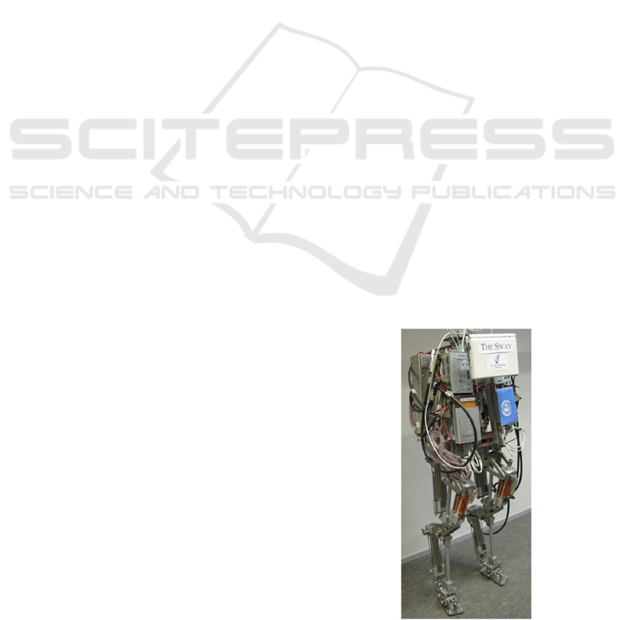
Figure 1: The SWAY, a bipedal autonomous walking robot.
Though the diversity is large, there are some
typical solutions. Widespread solution among the
humanoid type walkers, such as Asimo, is a Cardan
167
Jakubik P..
An Autonomous Biped - Concept and Design.
DOI: 10.5220/0003979701670176
In Proceedings of the 9th International Conference on Informatics in Control, Automation and Robotics (ICINCO-2012), pages 167-176
ISBN: 978-989-8565-22-8
Copyright
c
2012 SCITEPRESS (Science and Technology Publications, Lda.)

style cross joint, where the motor is closely placed
or integrated into the joint (Hirose, 2007, Honda
Online, Lim, 2007, Akachi et al., 2005). Another
solution is to employ transmission from a distantly
placed motor to the joint. Such is for example the
BiMASC legs (Hurst et al., 2007). Yet other
solutions are the application of the linear actuators
like pneumatic cylinders (Muscato, 2005), ballscrew
actuated drives or series elastic actuators (Robinson
et al., 1999).
In all cases the heart of the problem is the
insufficient directly available torque of the rotational
electric motors in small volume which would then
require gears or other mechanical torque amplifiers.
As a consequence either the coefficient of efficiency
would dramatically drop or otherwise special
arrangements are needed for the larger motor’s
placement. The application of gears substantionally
alters the dynamic properties of the controlled
mechanical equipment making it less reactive to the
control signals and more power intensive to achieve
a dynamic walking. Various recommendations to use
linear motors seem to recognize these problems, but
either the pneumatic or hydraulic actuators have
their own drawbacks in the human type walking
imitation. Though, the very same actuators may
seem successful in a larger category walking
devices, e.g. quadrupeds.
Another aspect is the interrelation between the
available mechanical designs with the sought control
algorithm. The conventional Zero Moment Point
(ZMP) method requires large flat soles, the motion is
a result of intense position or force control and not
meant for fast motion (Vukobratović, 2004). The
dynamic motion type algorithms assume light
construction and relatively weak motors. Several
dynamic walking algorithms applied to
kinematically not enabling designs, where the
control algorithms either necessarily distorted to
deal with the extra dynamic load posed by the given
mechanism or should use exaggerated driving
forces, circularly increasing the inescapable
mechanical burden for itself.
Sardain et al. has reviewed the typical
mechanical architectures of the biped robots in 1998
(Sardain et al., 1998). Since then the basic
approaches haven’t changed except one notable
exception which is the PETMAN of the Boston
Dynamics company (National Research Council,
2008). In most cases the motivation is to create a
mechanism for a given premeditated control concept
which is typically the ZMP approach. In another
case the type of mechanism is premeditated and the
theory was created afterward to explain the motion.
These are the passive dynamic walkers where the
Limit Cycle Walking (LCW) concept has been
worked out. In the third group the PETMAN robot
takes its root from jumping devices where the design
concept and the theory complement each other. In
yet another group a premeditated theory is being
applied to given robots not specifically designed for
exploiting the control concept. The Biomechanics
field is dealt with to explain the human motion based
on experimental observations. It does not vindicate
itself the task to design and construct human like
mobile devices.
These efforts are largely have been influenced by
the available resources. The aim of the most
laboratory walkers is purely to demonstrate walking
with a particular control concept on limited budget.
These walkers are typically small, lightweight
prototype where actuations are economized. These
are proof of principle models, based on minimalist
design on low budget. As such they are very much
constrained in functions. Industry backed research
does not limit the effort on mechanical design
necessary be applied to for a given control principle.
These are characterized on recurring control efforts
and well established control algorithms.
Biomechanics research has traditionally conducted
in universities with support of medical industry, but
their demonstrators are not meant to create full
fledged walking devices rather particular orthoses to
help locomotion. In our approach we are motivated
by the human body and control principle, and trying
to come up with a mechanical design on that
principle.
3 THE DESIGN CONCEPT
3.1 Design Objectives
The currently established aim is to accomplish a
human like walking, in style, in size and in
efficiency. This is best approached by human like
mechanical design. Previous walkers typically walk
on flat, even surfaces some can cope with mild
slopes and some can climb stairs. Moving on soft or
irregular terrain however raises the issue of adequate
mechanical design and control algorithms
(Vukobratović, 2009). Though hands are naturally
comes and utilized for the human walking they are
not essential for our purposes. Immediate application
areas of the human like design are in the rapidly
developing robotics fields like the Geminoid robots,
military and additionally the planetary humanoid
robots.
ICINCO2012-9thInternationalConferenceonInformaticsinControl,AutomationandRobotics
168
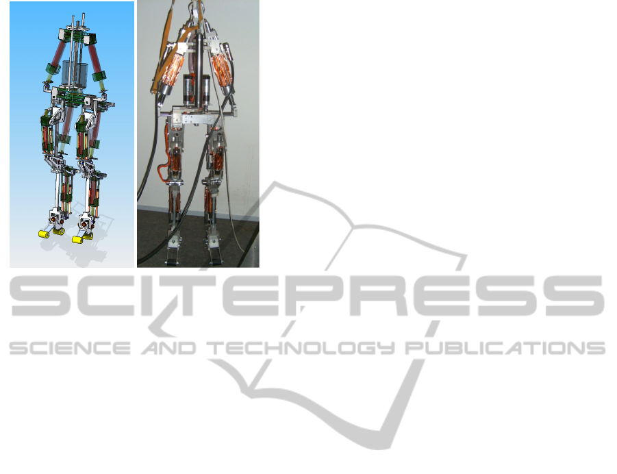
Figure 2: The skeleton design concept and realization.
The design objective is an energy efficient
motion in general. As such we took example from
the human body to achieve this goal. The
biomechanics field has studied and unveiled the
human motion characteristics in details for several
decades. However its synthesis will become possible
only with the developments of new powerful
actuators.
Recently some actuators available in both
commercial and research realms which suitability
worth to explore for dynamic walking. In fact having
the technology, custom made actuators of similar
techniques are fully possible. New materials
techniques and biomimetic actuators (Delude, 2005)
carry considerable promises but they have not been
explored yet in this applied mechanical field; thus
this technology-base allows a limited improvements
in the humanoid technology. Instead of optimizing
(mainly in parameters) an existing conventional
design we resorted to the vision of human motion by
abandoning the conventional design patterns and by
creating a mechanism functionally analogous to the
human one. Replicating the human motion has two
main aspects. The main mechanical characteristics
are easily adopted but clearly there is a very
sophisticated controller counterpart what the human
brain does. Simply, it can be either captured for
example by a neural network based controller as
patterns, or the sequential motion primitives and
their relations can be more carefully analyzed from
mechanical point of view and understood.
Understanding can lead to a simplified and energy
efficient control.
One of the main characteristics of the human
motion is the utilization of the natural dynamics and
reckoning with it through motion primitives ahead.
The result is a minimal effort control sequence, even
utilizing the momentary (or indeed foreseen)
interaction with the ground. From these follow that
minimal but well chosen forces are sufficient for the
locomotion. This allows us to venture to create a
mechanism and later a control algorithm to achieve
the energy efficient motion following the principle
of the human locomotion.
After substantiating the design ideal into the
skeleton design concept, we describe an achievable
control algorithm exploiting assumed specificities of
the walking mechanism. Then we describe the
embodied walking mechanism, named T
HE SWAY,
we analyze its mechanical features based on their
utility for enabling high dynamic mobility control.
After the kinematical and dynamical characterization
of the mechanism, the controlling system
architecture is outlined.
3.2 The Skeleton Design Concept
Though there is seemingly little difference among
those design concepts which tries to create a
humanoid like device, but the difference actually
creates a new class of walking robot with new kind
of capabilities.
The selected design concept follows an
anthropomorphic plan: a well separable human size
skeleton is actuated by detachable motors, whereas
the skeleton is a carrier for motors and all auxiliary
devices needed for autonomous operations. This is
illustrated by the Figure 2. The skeleton is a
standalone mechanism in itself capable of balancing
and its uncontrolled motion is similar to human
skeleton. Though this is an all-embracing intention,
engineering inevitability would shape the skeleton
accordingly. The skeleton has few but essential
internal constraints, in the hip as well in the knee.
The skeleton is human size, including a human
shape foot. The motors are electric, linear, direct
drive actuators and in principle detachable from the
skeleton. Actually, the present concept was
motivated by the employment of the electric linear
direct drive actuators.
In Section 3.3 we elaborate on the advantages
provided by the mechanism design while the
mechanism itself will be detailed in Section 4.
3.3 Control Algorithmic Aspects of the
Mechanical Design
The early works were more occupied with the
control algorithm itself to create the walking
AnAutonomousBiped-ConceptandDesign
169

behaviour, not realizing that the object which the
algorithm is acting on will have an influence on the
algorithm itself.
Traditionally several control concept able to
generate stable walking. These are the ZMP, LCW,
Dynamic Programming, Central Pattern Generator,
Genetic Algorithm, Neural Networks, trajectory
tracking etc. These are however treating a walking
task process like, they result in a long sequence
walking patterns. Our aim is to be aware of the biped
dynamics in every moment and be able to govern it
at will. Such control results in postural balance,
walking initiation, gaining momentum, slowing
down, turning, halting behaviours within the
walking behaviour. For such a goal the above
approaches are less suitable. We aim to apply
methods where the biomechanical consideration can
be quantified and governed. Such approaches are
e.g. the momentum control and reflex control. We
investigated an approach where the walking state has
been divided into a network of neighbouring
microstates, which covers all plausible dynamic
states in which the set of admissible control actions
known to be achievable and would lead the robot
dynamics into the neighbouring state. Then the
network of such states would realize the walking
behaviour in whole. A test of it demonstrated in the
Section 6.1.
The proposed mechanical design concept allows
the following operation, described for a swift
walking mode, as an example. Starting from a
configuration, where the swing leg’s heel touches
the ground, the impact is taken up by the shank
motor which smoothly curves the abrupt change of
the angular momentum vector toward the next
ballistic phase. This action is fully controllable
according to the walking principle. At this point the
support and swing legs’ role swapped. The support
leg’s knee is self locked under the weight of the
upper body. The upper body vertical orientation is
regulated by the support leg’s thigh motor, while all
the motors on the swing side are free and
unactuated. Advancing the body’s forward motion
the upper body sways toward the support leg where
an internal constraints prevent further leaning
sideway without any actuated effort and control of a
motor. Meanwhile, the swing leg’s shank motor
pushes the upper body to gain momentum, while all
other motors are free, since the support leg’s motion
is being driven by the inertia of the upper body. On
the next state, the knee motor raises the shank to
provide clearance between the foot and the ground
to pass the swing leg forward. The support leg’s
thigh motor regulates the upper body vertical
orientation while the ankle and knee remain
unactuated. Next the swing leg moves forward while
forming an underactuated system to drive. During
this motion the robot tends to fall toward the swing
leg without actuation. When the swing heel touches
the ground the cycle is recurring. Then the biped
works on the following principle: the gravity
actuates, inertia drives, constraints direct, motors
correct. Since the dynamics is analyzed at each
microstate a proper calculated driving or correcting
action could take place.
The main driving force is the gravity while joint
actions fulfil the role of coordinating the constraint
actions. Since the inertia takes the body with it,
passive joints move in trajectory free fashion. In
other words the motion control task becomes to plan
the actions of the expected internal and external
constrains based on the dynamics of the biped. The
symbiosis of mechanical design and the control
principle eliminates the need for force sensor
instrumentation; nevertheless this information is
easily derivable from the dynamics if so needed.
The enabler of the minimally actuated motion
logic above is the proposed mechanical design as
detailed in Section 4. It is also applicable for
extraterrestrial locomotion on soft or rough terrain
e.g. the Moon’s or Mars’.
4 THE MECHANISM
4.1 System Overview
The design process, regardless whether it is based on
systematic or intuitive approach is a highly personal,
creative and recurrent process. It is well manifested
itself in the variety of the designed bipedal walkers
in the past. Our design approach is to choose the
characteristically human kinematic and dynamic
features to follow. In addition the design ought to
facilitate the direct miming of the human walking
style. The following factors determine the
uniqueness of the proposed design:
1. weight bearing skeleton as a functional
element,
2. skeleton carries detachable motors,
3. bisected hip design on a spine,
4. mechanical motion limits in knee and hip;
when those are engaged they release or replace
actuator efforts serving functional purpose for
the control,
5. utilizing linear electric direct drive actuators,
and a
6. control algorithm which meant to utilize the
ICINCO2012-9thInternationalConferenceonInformaticsinControl,AutomationandRobotics
170
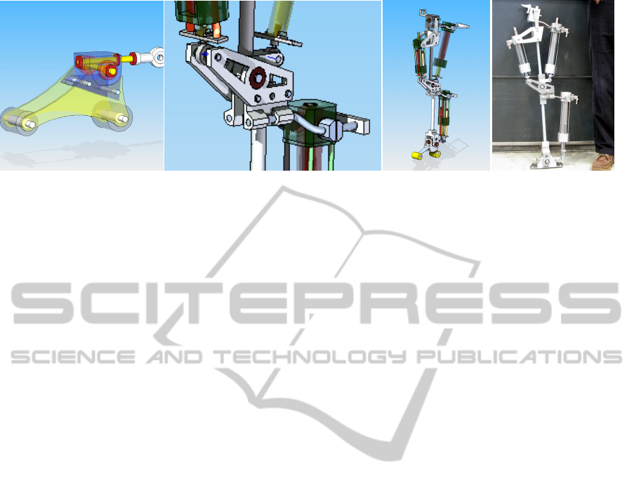
Figure 3: The foot, knee and the leg assembly.
natural dynamics of the mechanism, which is
focusing on a smooth transition of the upper
body part, having appropriate inertia.
The skeleton is compiled from simple aluminium
tubes to replace spacious casing. The tube elements
have diminishing weights but have sufficient
strength to carry the body. Thus the enabling
specificity is that the robot has no separate carrying
frame incorporating the motors and the joints, rather
it has functional elements (skeleton and motors)
separately – intentionally mimicking the human
structure (Figure 2).
4.2 Mechanical Architecture
4.2.1 The Actuators
Pneumatic and hydraulic actuators have been used to
create muscle like linear actuation earlier. They are
both powerful actuators but require extra complexity
for their infrastructure. Hydraulic actuation has all
the advantages of strength and size. However the
robot should have closed hydraulic circuit and the
pump on board with auxiliary components placed on
the trunk.
Rotational electric DC motors are widely
employed in the contemporary walkers. To achieve
strength it should employ high ratio transmissions
typically harmonic drives. However in this case the
actuator looses a direct connection to the actuated
mechanism injecting huge reflecting inertia and
friction and thus the whole walking mechanism
‘looses dynamics’ a chance to the inertial control. A
chance, that the gravitational inertia is a direct
actuation force, rather than an effect which should
be compensated by the control algorithm. This
necessitates employing position control of the DC
motor versus a current control producing direct
torque. Nevertheless, with rotational electric motors,
linear motion can be generated. Notably series
elastic actuators can provide strength and
compliance between the actuated constructional
elements. But beside the problem of producing
higher force, which would need higher strength
motor, thus heavier and more sizeable motor, the
long term operational issues like wear, thermal
balance also come forward. With high transmission
ratio the agility of the actuation is lost.
Linear electric direct drive motors are new
comers in the biped field, and not tested for this
application. They evade the disadvantages of the
above actuation types. Comparing with the hydraulic
pistons they are somewhat bigger and much weaker,
but as a system element much more economic in
terms of total weight and size occupancy. The linear
electric direct drive motors have better dynamic
properties and simple direct output force control
capabilities. Since its force output is limited, the
question arises, what control approach is possible at
a limited force budget. The proposed solution to this
quest is to design such a mechanism which
minimizes the need of exciting the dynamics of the
mechanism and let the external and internal forces
act such that the walking trajectory will be resulted
by the robot’s own natural dynamics but guided by
the actuation forces. This is motivated by the
observation that at habitual walking the man is taken
forward by its own inertia and not by continuous
force efforts. Then applying the liner electric direct
drive motors to the control concept of Section 3.3,
its feasibility has been tested by simulation and
practical tests (Section 6). The linear motors are
placed so on the mechanism that it optimizes the
availability of forces from the actuators along its
motion interval, as the function of the desired forces
due to the dynamical task requirements. A well
designed control system then allows introducing
programmed compliance between the machine
elements, as well as facilitating to the energy
recuperation from the walking motion. We have
acquired commercial-of-the-shelf LinMot linear
AnAutonomousBiped-ConceptandDesign
171
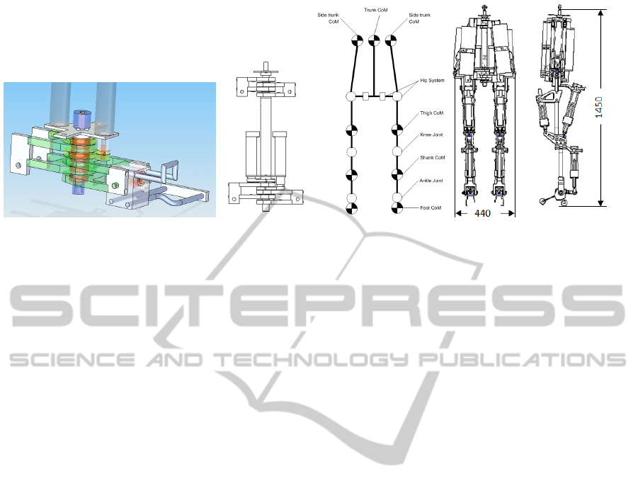
Figure 4: The hip and hip joint, hip and shoulder on the spine, kinematical scheme, trunk and biped with measurements.
motors which are permanently actuated synchronous
servo motors for this prototype (LinMot Online).
Use of custom made linear induction motors also
matches the design concept. Further motivation of
linear actuators is that with the advance of
nanotechnology and microprocessing, advent of
artificial muscles can be expected in the future
(MYOROBOTICS, Delude, 2005), which would
compactify the placement of the future linear
actuators. According to our other application
intention, extraterrestrial bipeds on the Moon and
Mars can be actuated by linear electric direct drive
motors, which place emphasis on the correct
dynamic control with reduced need for static force
budget.
4.2.2 Foot and Ankle
The foot provides contact to the ground and the
ankle would activate the robot. Several authors
assign fundamental role to the shape and function of
the foot. Indeed the foot is which smoothly shapes
the momentum of the whole biped at every step into
its desired controlled direction. Its shape, design,
mechanical properties have been designed diversely.
The conventional ZMP control principle requires
specially instrumented flat foot design – for typically
moving on even surface. The foot typically made as
a flat metal element supposing that the robot places
the whole sole from above vertically, then when
down, the whole robot is pivoting around the support
leg’s ankle. Occasionally the foot is morphed to the
human foot shape or a real shoe is put on the foot. In
other cases the toe is made to be rotated around and
increases the surface of contact while executing leg
pushing or the heel is shaped to absorb the orthosis’
impact. Some authors (Geyer et al., 2006) also
incorporate the leg compliance as a key to the
walking principle.
The proposed ankle is powered in the sagittal
plane, but it is not powered in the frontal plane
around the roll axis. This still allows a forward
propelling motion and it also can exert forces for
other kind of motion primitives (i.e. postural balance
and stepping). The sideway actuation is obsolete in
this dynamic walking approach (as opposite to the
ZMP walking approach) since the biped locomotion
principle does not require it. In extreme case,
walking with stilt does not require at all a powered
foot. However the anthropomorphism is important in
our case. We employ rubber cylinders of proper
grade for this prototype to provide good stiction to
the ground. The toe is utilized for leg pushing and
the heel for absorbing landing impacts. The rubber
cylinder passive compliance accommodates to the
unevenness of the surface and the weight shift of the
mechanisms as it walks. The shank motor handles
both the impact at heel touch down and the leg push
with the toe, together the passive foot, eliminating
the need of built-in design and control complexities.
The shank motor arm is placed higher to allow a
firmer stance of the sole on the (uneven) ground
when standing or when the shank motor pushes the
toe when walking. This prototype however
oversimplifies the foot design at the expense of
emphasis their main functions.
4.2.3 Knee
The knee design is the other most important element
which influences this walking concept. The knee has
a sole function to raise the shank to make clearance
when the swing leg is brought forward. At the
conventional solution the support leg’s knee
actuation also should oppose the significant static
and dynamic forces. Some solutions use
programmable mechanical locks to eliminate the
ICINCO2012-9thInternationalConferenceonInformaticsinControl,AutomationandRobotics
172

need for actuation. In our proposal we mimic the
human knee function constraining the joint motion
in the forward moving direction just a little bit over
the vertical neutral position. With this the robots
own weight locks the knee without any actuation
when standing still and when the stance leg follows
the trunk motion forward.
4.2.4 Thigh and Shank
The main design elements in the thigh and the shank
are the load carrying bones. Linear motors are
suspended on that structure. The thigh motor has two
functions. When the corresponding leg is on the
ground it exerts torque on the trunk, otherwise the
same motor raises and swings the leg. A cantilever
introduces limited flexibility between the actuator
and the major upper body mass. The thigh joint
limits the allowable swing of the leg and it can be
designed for various values. If the shank motor
neglected the biped should walk as on stilts.
4.2.5 Spine
The main constructional element is the spine (Figure
4). It carries any other elements. The main design
coordinate system is attached to this element. It is
simply a tube.
4.2.6 Hip and Shoulder
From design point of view, the placement of sizable
powerful motors while ensuring the desirable
kinematic functionality is the central problem. To
resolve this issue several unique approaches have
been proposed. Our solution is shown on Figure 4. It
is a
bisected hip. Its sides are directly connected and
rotating around the spine, with double function to
rotate and hold the hip joints. To increase the
rigidness and reduce the weight these identical
elements are split and interlaced with each other.
Each side of the hip is actuated relative to the spine
by DC motors. The hip carries a two degrees of
freedom hip joint, which in turns carries the thigh.
The hip’s task is either to ensure change of the
trunk position relative to the ground when the robot
is standing or allows the legs move relative to the
vertically kept trunk when the robot is walking.
Considering the idealized closed loop of the
kinematic chain formed by the two hips and legs and
the ground, difficulties might arise, since legs’
geometric constraints cannot be always satisfied.
This issue however will be eliminated by the foot
flexibility.
The hip and the shoulder design is analogous. The
shoulder carries the waist actuator. The waist motor
connects the upper shoulder and the hip joint. The
hip joint constraint in lateral plane is realized by
limiting the waist motor stroke – simplifying the hip
joint. This constraint plays a functional role as
described in Section 3.3. It also releases the waist
actuators from any large counterbalancing efforts.
4.2.7 Leg
The leg (Figure 3) as an aggregate is built from the
hip joint, thigh, knee, shank and foot.
The leg can be slightly pulled beneath the trunk,
allowing minimizing the sway of the torso while
walking, eliminating the counterbalancing forces
and dramatically changing the character of the
walking, with favourable consequences for the
algorithm sophistication and the energy
consumption.
4.2.8 Trunk
The trunk (Figure 4) as an aggregate is built around
the spine. The trunk comprises the hip and shoulder
at the two ends of a connecting spine. The trunk and
thus whole robot is composed from two identical
and symmetric parts rotating around the spine axis.
The trunk is also a carrying element for the motor
controllers, the computer infrastructure, the sensor
and the energy subsystems which are built on a
slightly displaceable chest element whose rotation
axis shares the hip joint axis on both biped sides. Its
presence is not inevitable but helps to modulate the
biped’s swaying motion. Additional elements like
batteries, various electronics and computers
connected to the spine.
No separate casing for the trunk is designed, thus
the legs are not connected to a common base. The
hip and shoulder are bisected and the corresponding
joints turning relative to the spine. This resulted in a
solution, where (i) mechanically, the constructional
elements are minimized, since only the actuators, the
joints and minimal additional material are present;
and (ii) functionally, where the two halves of the
biped are independently suspended from a central
spine. Turning will be similar to the human, where
the whole torso making the turn exploiting the
stabilizing effect of the body’s inertia when
controlling the turning.
4.2.9 Additional Elements
The whole robot is built from aluminium parts
except the small parts like ball bearings, etc. The
joints can contain flexible, vibration damping
AnAutonomousBiped-ConceptandDesign
173

sockets between the structural machine elements.
Furthermore explicit energy conserving springs also
can be easily accommodated into the mechanism
since the linear motors can automatically comply to
the displacements when force control is applied.
4.2.10 The Biped
The biped (Figure 4) is an aggregate of the legs and
the trunk. The construction is modular, and care has
been taken to use the simplest functionally necessary
machine elements for each module. Additional
elements are the cabling, add-on sensor and control
devices, which introduce perturbations for the
control algorithm.
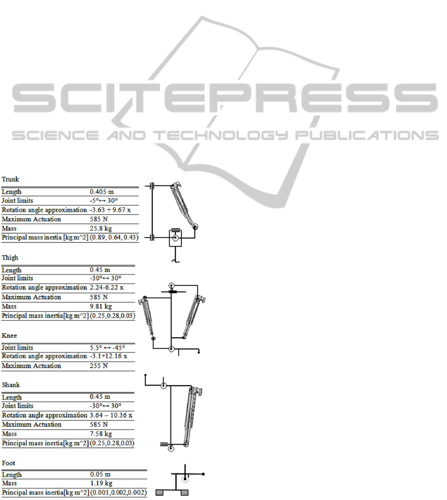
Our kinematic and dynamic analysis is based on
the geometric and physical description of the biped’s
CAD model (Table 1). Rotation angles can be
linearly approximated as a function of the stroke
with rms less than 0.01 rad in the operation range of
the joints, simplifying the calculations. The overall
system specification (Table 2) is to be compared to
Asimo specification (see the References section).
5 COMPUTER SYSTEM
ARCHITECTURE OUTLINE
What follows is a preliminary control system design
for the above described walking mechanism. The
system is build up from ‘independent’ subsystems
(modules). Independent in the sense, that their
functionality constrained to a topologically separated
module; they are developed and tested
independently; and they can be replaced by another
similar module without changing, at least
significantly, other subsystems. Thus the robot has
the following subsystems: mechanical, energy,
sensory, control, motor, HMI, safety, actuator units,
and the walking algorithm domain. The information
flow between the subsystems is realized by the
computer infrastructure.
The biped’s computer infrastructure (Figure 5)
encompasses hardware and software, and when it
combined with the mechanics it constitutes a
controllable device. It contains a central computer
(CC), human machine interface (HMI), energy
subsystem (ES), sensor subsystem (SS), a walking
algorithm computer (WAC), a motor hub (MH),
motor controllers (MC) and motor drivers (MD).
The CC supervises functionality of all modules. It is
an autonomous unit (GumStix), permits and
oversees the robot operation, checks the operability
and status of all other subsystems, also can decide
Figure 5: The Sway biped, modularized computer
infrastructure.
and able to shut down the system. It has own logic to
decide and overview (based on network messaging)
what constitutes a normal operational regime of the
robot. The WAC (EEE 901 PC) is occupied strictly
only with the logic of the experimental walking
algorithm. Its input is the sensory and the user’s
command information. It outputs a compact motion
command to MH. The SS centers around the
SensorHub (SH) (PC-104), which acquires, process
and stores all sensory information of the robot. It is
connected to the WAC. (In our experimental
embodiment the motor controllers directly can have
access to the sensor data). The SensorHub operation
is programmable by the WAC. The communicated
sensor data, and the choice of sensor data processing
with parameters are selectable, events are
parameterizable, etc. The MH (PC-104) distributes
and oversees all motor related communications,
trajectory generation, scheduling and diagnosis. The
ES (PC-104), designed for an independent working.
Among its functions are to manage the battery units,
as well as roles in the regenerative control of the
actuators. The safety subsystem monitors the
resulted actions of selected modules. It relies on
common sense self-diagnostic elements of the other
subsystems: energy supply, range of actuator
motion, stability of motion, motors’ and computers’
health, etc. Each computer units are implemented by
the least necessary category microcomputers.
Chiefly CAN, but ad hoc Ethernet and SPI
networking have been used.
6 FROM CONCEPT TO
CONSTRUCTION TESTS
To gain confidence of the suitability and the
expected dynamic behavior of the biped the
ICINCO2012-9thInternationalConferenceonInformaticsinControl,AutomationandRobotics
174
assembled mechanism underwent several tests on
different level.
6.1 Simulation Studies
The simulation studies have been carried out in
Matlab/Simulink/SimMechanics environment.
6.1.1 Oscillatory Motion in the Frontal
Plane
The frontal motion test includes testing the logic of
the rocking motion in the frontal plane, the
availability of the motor strength to rock the whole
biped and testing the effect of the hip limit constraint.
In one test the stance of the biped has been decreased,
correspondingly the need for the waist motor actions
to drive the rocking motion has been reduced. The
lateral oscillation has been sustained by the stepping
motion of the legs. This test shows that while
inclining the design toward instability the needed
driving efforts are reducing while the need for the
Table 1: Main Kinematic and Dynamic Parameters of the
Individual Body Segments.
agile motion control is increasing
6.1.2 Step in the Sagittal Plane
Motion in the sagittal plane gives a qualitative
judgment of the dynamic behavior of a massive
object with a possible control algorithm. While the
final 3D motion generation is different, we
implemented the elements described in Section 3.3.
Simulation trials, which resemble Moon and Mars
environment with reduced gravity and soft ground,
have been also carried out for the proposed design.
6.1.3 Homing Calibration
In physical systems the exact position of center of
masses of the body elements for the finally prepared
prototype are not exactly known. Homing creates a
reference configuration where the robot could stand
with no actuation without collapsing. Homing is
complemented by simple mass measurements to
create an approximate dynamic model for the biped.
Homing is based on minimizing the shank and thigh
motors’ current which keeps the biped in a vertical
stable position without actuation.
6.2 Practical Tests
The motors have been tested individually for
function, strength and agility (Peralta et al., 2009).
Then collective test of linear motors has been carried
out producing stable postural balance around zero
nominal current actuation, actuating the thigh and
shank motors under LQR on one side, maintaining a
stable posture even when manually shaking the
biped and all other joints were unactuated. When the
sagittal stance formed a triangle with the legs the
robot could produce a stable balance with a sole
thigh motor actuation while all others joints were
unactuated. The waist motors of the biped were
tested which overwhelmingly could overturn the
robot sideway.
Motor thermal behaviours were tested by static
and dynamic tests for the most loaded motors. Thigh
motors withheld the fully stretched leg in the air for
several minutes without warming. The knee motors
could intensively raise and lower the shank several
tenths time before the temperature limit is reached
and the motor controller cut its operation. This
behaviour is due to the lower grade commercial off-
the-shelf motor, selected intentionally, which force
constant is half of the thigh’s motor. This issue has
been fixed by cooling the motors and applying a
preloaded spring to the knee. The motor change
however is not necessary to conduct tests of limited
AnAutonomousBiped-ConceptandDesign
175
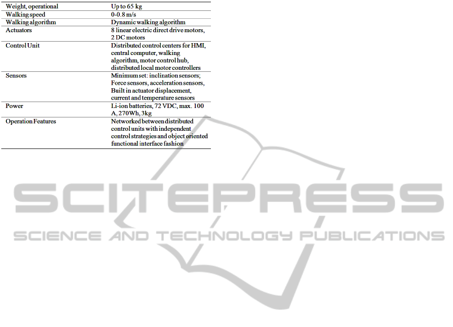
Table 2: The SWAY specification.
length of walking sequence. Further work may
employ different brand or custom made linear
electric direct drive motors.
7 CONCLUSIONS
We have proposed and developed a biped robot
which key aspects are the anthropomorphism and the
use of linear electric direct drive actuation. The
robot bears comparable anthropomorphic geometric
and mass values to serve further studies and
experiments for dynamical walking. Its control
structure follows modularity principles with its
components functionally distributed but each are
completely integrated. The proposed robot design’s
incremental testing and justification is underway and
reached the stage of its complete but preliminary
postural balance control. The biped’s motion is
smooth and silent. Further work shall address the
control algorithms which capable to exploit the
kinematical advantages of the proposed mechanism.
REFERENCES
Akachi, K., Kaneko, K., Kanehira, N., Ota, S., Miyamori,
G., Hirata, M., Kajita, S., Kanehiro, F., 2005.
Development of humanoid robot HRP-3P. 5th IEEE-
RAS International Conference on Humanoid Robots,
vol. 5(5), pp. 50 – 55.
Delude, C. M., 2005. MIT closes in on bionic speed.
Available online at http://web.mit.edu/newsoffice/
2005/muscle.html.
Geyer, H., 2011, What breakthroughs does the field of
legged dynamics need? Dynamic Walking 2011.
Geyer, H., Seyfarth A., Blickhan R., 2006, Compliant leg
behaviour explains basic dynamics of walking and
running. Proc R Soc B 273: 2861–2867.
Hirose, M., Ogawa, K., 2007. Honda humanoid robots
development, Phil. Trans. R. Soc. A 2007 365, 11-19.
Honda, Online,
http://world.honda.com/ASIMO/history/technology3.h
tml, Available 1.2.2012.
LinMot, Online, Data Book: Industrial Linear Motors,
(Edition 15). Available: http://www.linmot.com/
Lim, H., Takanishi, A., 2007, Biped walking robots
created at Waseda University: WL and WABIAN
family. Phil. Trans. R. Soc. A 2007 365, 49-64.
Hurst, J., W., J. Chestnutt, E., Rizzi, A., A., 2007. Design
and Philosophy of the BiMASC, a Highly Dynamic
Biped. 2007 IEEE International Conference on
Robotics and Automation, vol. 10(14), pp. 1863 –
1868.
National Research Council, 2008. Soldier Protective
Clothing and Equipment. The National Academic
Press. (Design Challenge: Robotic Capability for
PETMAN).
Muscato, G., Spampinato, G., 2005. A Multi Level
Control Architecture for a Pneumatic Robotic Leg.
ETFA2005 10th IEEE International Conference on
Emerging Technologies and Factory Automation,
Catania, Italy, 19-22 September 2005.
MYOROBOTICS, A framework for musculoskeletal
robot development. 7th Seventh Framework
programme, European Communities.
Osuka, K., Sugimoto, Y., 2005, Where is the Secret of
Walking Concealed? IEEE Int’l Conf. on Robotics and
Biomimetics. pp. 788-792.
Peralta, J., Ylikorpi, T., Gulzar, K., Jakubik, P., and
Halme, A.,2009, Novel Design of Biped Robot Based
on Linear Induction Motors. in Proc. International
Conference on Humanoid Robots.
Robinson, D., W., Pratt, J., E., Paluska, D., J., Pratt, G.,
A., 1999. Series Elastic Actuator Development for a
Biomimetic Walking Robot. International Conference
on Advanced Intelligent Mechatronics, September 19-
23, 1999 Atlanta, USA.
Sardain, P., Rostami, M., Bessonnet, G,, 1998, An
Antropomorphic Biped Robot: Dynamic Concept and
Technological Design. IEEE Tr. On SMC, Part A, Vol.
28, No. 6.
Vukobratović, M., Borovac, B., 2004. Zero-moment
point—Thirty five years of its life. International
Journal of Humanoid Robotics, Vol. 1, No. 1.
Vukobratović, M., Borovac, B., 2009. Why Should
Robots in Unstructured Environments Perform a
Dynamically Balanced Regular Gait? Acta
Polytechnica Hungarica vol. 6(1).
ICINCO2012-9thInternationalConferenceonInformaticsinControl,AutomationandRobotics
176
