
Simulation of Backflow in Automotive Body Assemblies
Jaedeuk Yun
1
, Sunghoon Lee
1
, Jianhui Fu
1
, Jungwoon Lee
1
, Yoongho Jung
1
and Sungbae Park
2
1
School of Mechanical Eng., Pusan National Univ., Busan, 609-735, South Korea
2
Body Manufacturing Eng. Team #3, Hyundai Motor Company, Ulsan, 683-791, South Korea
Keywords: Drainage, Backflow, Octree, Voxel, Gap, CAD.
Abstract: The many parts required for aircraft and automotive development are developed by functional or sectional
design groups for efficiency. Interferences and gaps can be found when the parts and subassemblies from
those design groups are to be assembled. When rainwater enters the spaces between parts and there is not
sufficient drainage, the rainwater within the structure can backflow to gaps or unexpected outlets, which
may cause severe problems of part corrosion and electric shock. We have developed a method and a
program to simulate backflow of rainwater within spaces between automotive parts; the method can find
unexpected outlets and gaps. The developed program can simulate not only simple liquid flows, but also
division and joining of flows with multiple channels. The developed method can also be applied to aircraft
and ship design.
1 INTRODUCTION
Large assemblies such as automobiles, aircraft and
ships have the common characteristic of requiring
huge numbers of parts to be assembled. For such
large assemblies, most developing companies
accelerate the design processes with many design
engineers working concurrently. Concurrent design
with functional or sectional design groups may
reduce development time, but it may cause many
problems of interferences and gaps between parts
that are designed by different designers or design
groups. In particular, gaps between parts can cause
fatal problems of inflow to cabins or other spaces.
Most parts for passenger cars are made of thin
plates to reduce the vehicle weight, and there are
empty spaces between thin parts that are provided to
increase the car body stiffness. If there are gaps
between exterior parts of the car body, rainwater and
water from puddles on roadways can enter the cabin
directly or move through the empty spaces between
body parts. Even though design engineers include
appropriate drainage paths, if the drainage is too
small for fast discharge of the inflow, water may fill
the spaces. This situation may cause corrosion of
interior parts or fatal problems of electric shock and
malfunction if the water enters the electric system.
To check for such problems at the design stage,
designers check gaps between parts in suspect
regions with cross-sectional drawings that are
generated from the assembly model. However, it is
almost impossible for design engineers to check the
gaps of complicated three-dimensional flow paths
with two-dimensional sectional drawings.
To resolve this kind of problem, previous
methods such as searching empty spaces of the
assembly, simulation of fluids (Premoze et al., 2003;
Foster and Metaxas, 1996; Losasso et al., 2004;
Ramaswamy and Kawahara, 1987; Harlow and
Welch, 1965) and mold flow analysis (Broyer et al.,
1975) can be considered. However, those methods
are not adequate for the present purpose, which
requires searching for gaps between parts of
complicated shape and simulating the backflow of
water in the gaps to check whether the backflow
path reaches unwanted places.
We propose a method of searching space
between thin parts of complex shape with free
surfaces automatically to simulate backflow in the
searched space. With the simulation program we
have developed, designers can check the path and
outlet positions of backflows in the design stage, and
can handle the problem of inflow into the cabin by
improving their design before manufacturing.
351
Yun J., Lee S., Fu J., Lee J., Jung Y. and Park S..
Simulation of Backflow in Automotive Body Assemblies.
DOI: 10.5220/0003981903510356
In Proceedings of the 2nd International Conference on Simulation and Modeling Methodologies, Technologies and Applications (SIMULTECH-2012),
pages 351-356
ISBN: 978-989-8565-20-4
Copyright
c
2012 SCITEPRESS (Science and Technology Publications, Lda.)
2 OVERVIEW OF BACKFLOW
SIMULATION
Most car body parts are of thin plate with free
surfaces; the shapes of the gap spaces between those
parts can be complicated. For searching to identify
these spaces automatically, we use a method for
representing the decomposition of the given parts
and spaces that is not limited by the complexity of
the object to be represented and is also efficient for
searching for interior spaces automatically. The best-
known methods for expressing three-dimensional
objects as decomposition models are the voxel and
octree representations (Frieder et al., 1985; Tang,
1992). In this paper, we will modify the combined
method of voxel and octree representation that was
proposed by Rodriguez (2009).
The proposed algorithm starts with input models
having data formatted using STL, which is widely
adopted as a standard CAD model data format. Next,
after representing all parts as octrees of input
resolution, it converts all octants into voxels of the
same size as the minimum octant of the octree. Then
it classifies the interior and exterior spaces of the
input assembly model. Finally, it simulates the
backflow of water within the interior spaces
represented as voxels. A more detailed explanation
is given in the following sections.
3 SEARCHING FOR GAP
SPACES AMONG PARTS
3.1 Generation of Decomposition
Model
The voxel representation method has the advantage
that it is simple to represent a given object and easy
to find neighbor elements. However, small voxels
require more memory and more calculation time is
required to classify each voxel as interior or exterior
to the given assembly. The octree representation
method recursively divides ‘partial’ elements that
contain the boundary of the given object into
elements of the desired resolution. Therefore, the
octree method has the advantages of a smaller
number of elements and less calculation time than
the voxel method. On the other hand, the voxel
representation method can simulate flows more
realistically with uniform elements than the octree
method. In this paper, we combine the voxel and
octree methods to exploit the advantages of both
methods.
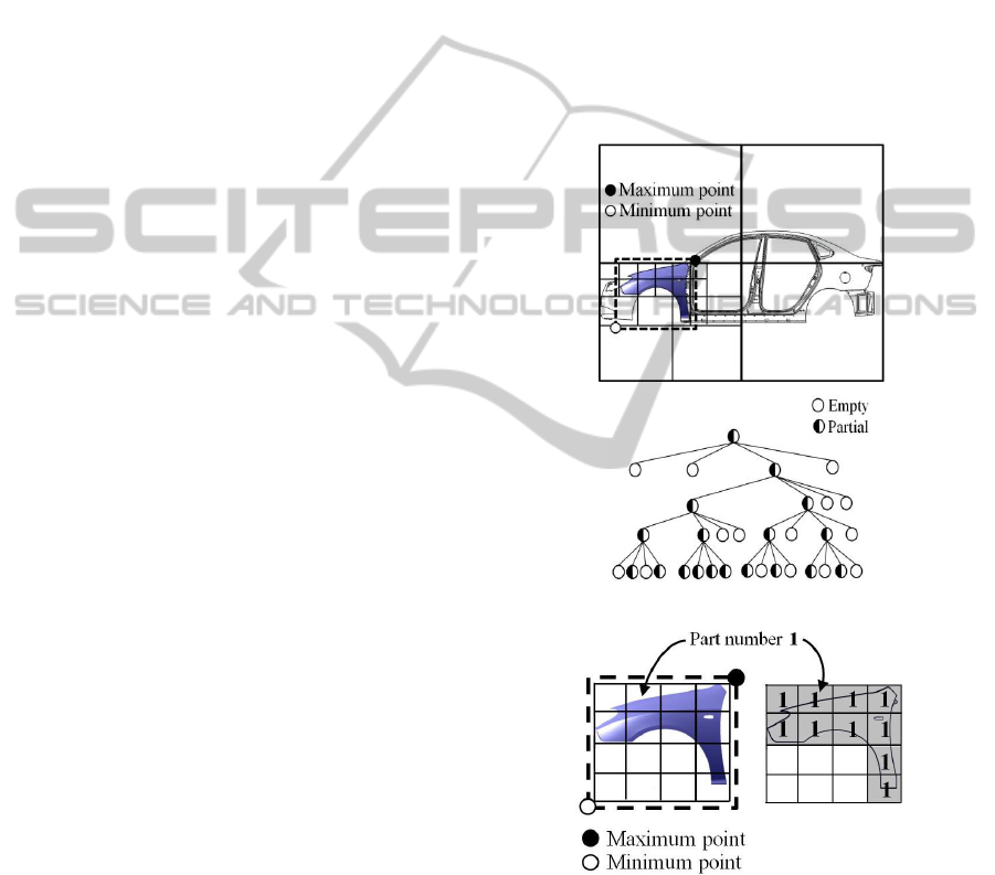
For understanding of the combined method, we
will explain using the two-dimensional illustration
shown in Figure 1. First, we represent each part as
an octree (quadtree in Figure 1(a)) of which the root
octant is a cube (the main box in Figure 1(a))
containing the main assembly, instead of making the
root octant the part itself, as shown in Figure 1(a).
Then, we divide the cube (the box in Figure 1(b))
containing all ‘partial’ octants of the octree into
voxels of the same size as the minimum octant of the
octree, as shown in Figure 1(b). This approach has
the following advantages. First, it is much faster
than the original voxel representation method.
Second, it is easier and faster to find neighbor
elements than in the original octree representation.
(a) Octree generation
(b) Voxel generation
Figure 1: Voxel generation from octree representation.
To generate the decomposition model of the
assembly, we combine the voxel models of each part
using Boolean operations, as shown in Figure 2,
which shows the process of generating the
decomposition assembly model of two parts in two
dimensions. When the voxel models for Part 1 and
SIMULTECH 2012 - 2nd International Conference on Simulation and Modeling Methodologies, Technologies and
Applications
352
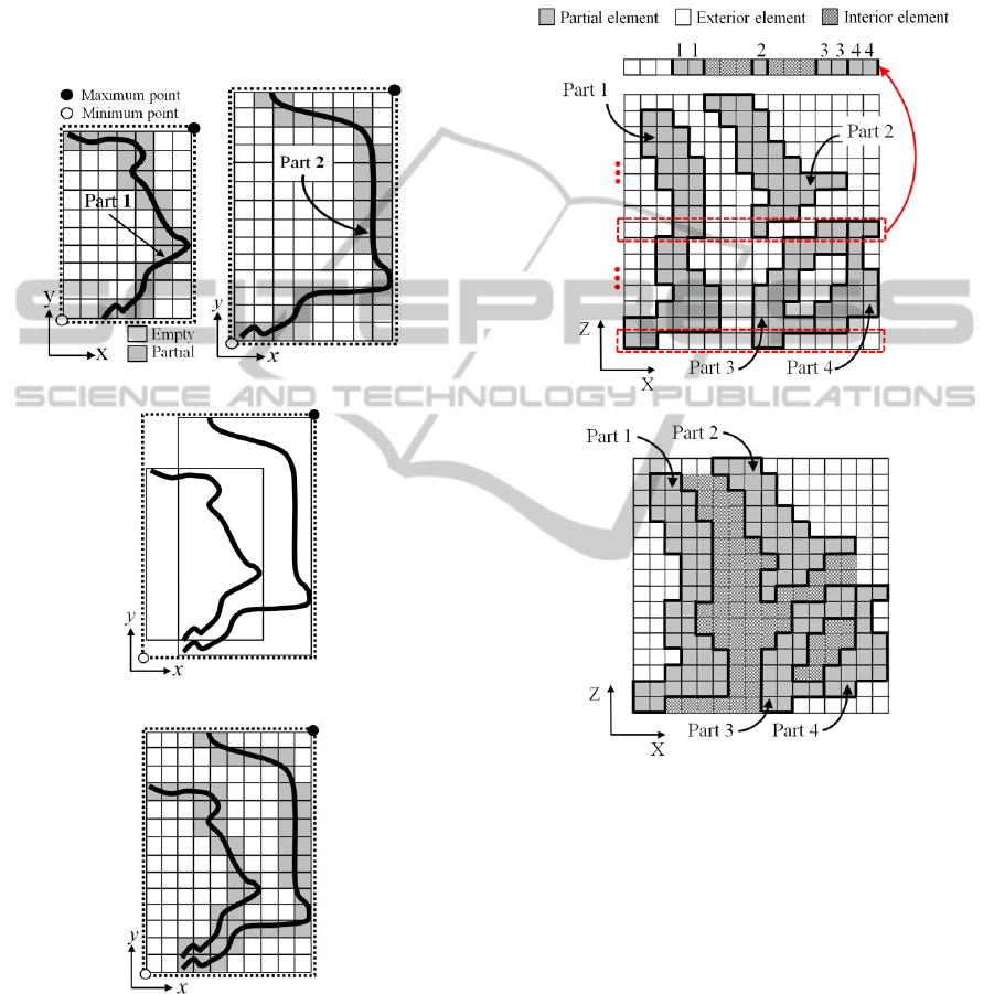
Part 2 are generated, as shown in Figure 2(a), we
calculate the minimum cube (the box in Figure 2) as
in Figure 2(b) to contain both voxel models. After
dividing the minimum cube into voxels of the same
size as the voxels of the parts, we map each voxel of
Part 1 and Part 2 onto the corresponding voxel of the
minimum cube, as shown in Figure 2(c). This
process continues for all parts to generate the
decomposition model of the whole assembly.
(a) Voxel model of each part
(b) Mapping
(c) Assembly decomposition model
Figure 2: Boolean operation for assembly model.
3.2 Searching for Interior Elements
When parts of free surfaces are assembled, it is
difficult to define the boundaries between gap spaces
between parts and exterior spaces of the assembly.
In this paper, we propose an algorithm to define the
boundary when each part is represented by a
decomposition model of voxels. To understand the
proposed algorithm, we will explain using two
dimensions as shown in Figure 3, in which the
model consists of four parts.
(a) Interior elements in X-axis direction
(b) Result of searching interior elements
Figure 3: Interior elements among parts.
With the decomposition assembly model of all
parts, the proposed method searches for every voxel
within the gap spaces as follows. Our method visits
each voxel of the decomposition assembly model in
the X-, Y-, and Z-axis directions, searching for
voxels that are between ‘partial’ voxels that belong
to different parts, to be classified as ‘interior
element’ (IE) voxels. For example, in Figure 3(a),
visiting voxels from left to right (the X-axis
direction) in the eighth row from the bottom, we
classify the voxels in the sixth, seventh, and eighth
columns as IEs, because they lie between partial
elements of Part 1 and Part 2. The voxels in the 10th,
11th, and 12th columns are also IEs because they lie
between partial elements of Part 2 and Part 3. We
Simulation of Backflow in Automotive Body Assemblies
353
continue the process from the bottom to the top row
to search for all interior elements in the X-axis
direction. In the same way, after searching in the Y-
axis direction, we can find all interior elements, as
shown in Figure 3(b). For the three-dimensional
case, we also search in the Z-axis direction.
4 BACKFLOW SIMULATION
ALGORITHM
In this section, we will describe the simulation
algorithm for backflow when fluid fills the interior
spaces between car body parts. For the purpose of
the algorithm, we will call a voxel that is being filled
with fluid ‘half occupied’ (HO), and a voxel that has
been completely filled ‘completely occupied’ (CO).
4.1 Backflow Simulation in the Vertical
Direction
First, the algorithm searches the voxel model for the
IEs that are on the lowest level or have an exterior
element (EE) below, to form a current layer (CL)
with all neighboring IEs. We will describe the
algorithm for forming the CL in the next subsection.
Next, when there is any IE below the CL during
the simulation process, the status of all elements of
the CL is set to HO, and the layer below the CL is
made a new CL with all neighboring IEs on the
same level. However, when there is no IE below the
CL while there is any IE or HO element above the
CL, the status of all elements of the CL is set to CO,
and the layer above the CL is made the new CL with
all neighboring IEs and HO elements on the same
level. All CO elements are regarded as filled with
fluid. This process continues until there are no IE or
HO elements above the CL. This approach allows us
to simulate forks into several streams as well as
joining of flows.
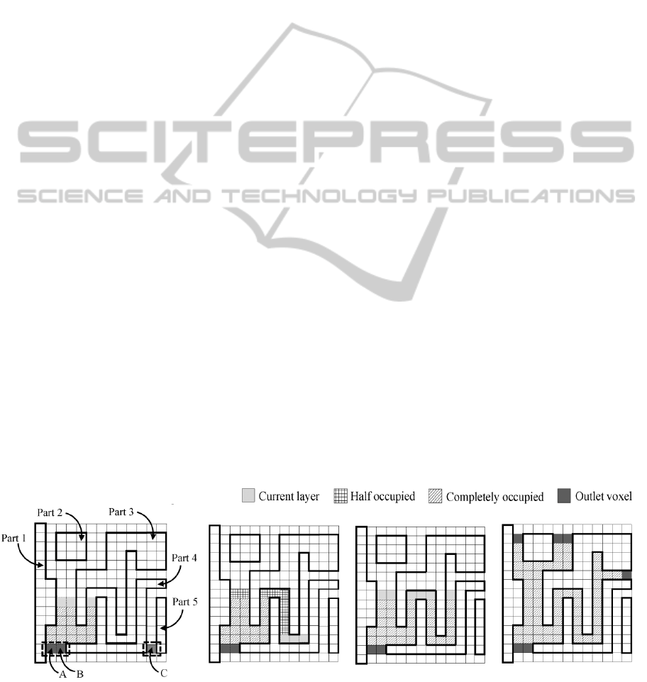
For understanding of the proposed backflow
algorithm, we will explain with the two-dimensional
illustration in Figure 4. The algorithm has five parts.
First, the algorithm searches from the lowest layer
for IEs that are above EEs, such as voxels ‘A’, ‘B’
and ‘C’ in Figure 4(a). When the user selects one of
these voxels, for example ‘A’ or ‘B’, the algorithm
forms a CL including the selected voxel. Because
there is no IE below the CL, the algorithm searches
for an IE above the CL and makes the layer
including the IE a new CL, while it changes the
status of all voxels of the previous CL to CO. This
process continues until the seventh layer from the
bottom in the case shown in Figure 4(a). At the
eighth layer, there are IEs below the CL, so the
algorithm searches downward layer by layer until it
reaches the bottom, as shown in Figure 4(b). Then,
because the CL at the bottom does not have any IEs
below, the process continues upward again, as
shown in Figure 4(c). When forming the CL,
separate HO elements at the same level as the CL
are included as CL elements. The algorithm
continues until there are no IE or HO elements
above the CL, as shown in Figure 4(d). The
proposed algorithm can simulate not only filling
enclosed spaces between parts, but can find
positions of outlet that can be passages of fluid into
the cabin. If the user selects voxel ‘C’ as the starting
CL, the algorithm will simulate a separate filling
process for the separate gap space.
4.2 Backflow Simulation in the
Horizontal Direction
We now describe the process of searching for all
elements of the CL that are on the same level and are
to be filled with fluid. When an IE in a layer is
(a) (b) (c) (d)
Figure 4: Algorithm for backflow simulation in the vertical direction.
SIMULTECH 2012 - 2nd International Conference on Simulation and Modeling Methodologies, Technologies and
Applications
354
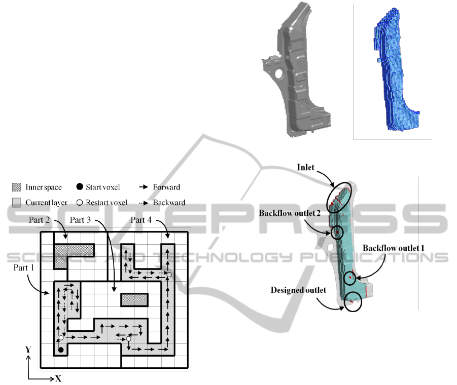
identified as a current IE, the algorithm searches for
neighbor IEs that are left, forward, right, and
backward from the current IE. When it finds a
neighbor IE, it makes that neighbor the current voxel
and changes the status of both elements to HO. The
process continues until the current voxel has no
unsearched neighbor IEs. The algorithm continues to
return to a previous voxel recursively while there is
an unsearched neighbor IE, to search again for
neighbor IEs. The solid arrows in Figure 5 show the
search direction while the dotted arrows represent
the returning process when the current voxel has no
unsearched neighbor IEs. The proposed algorithm
can find all voxels that are within an enclosed
boundary on the same level.
Figure 5: Algorithm for filling simulation in the horizontal
direction.
5 APPLICATION EXAMPLE
We have implemented the proposed algorithm using
Microsoft Visual Studio 2008 and applied it to
assemblies of real automotive parts. Figure 6(a)
shows the input STL models of an outer panel, front
pillar, and inner pillar, while Figure 6(b) represents
the result of searching for interior spaces between
the parts as voxels. Figure 6(c) shows the results of
the backflow simulation, which automatically found
several outlets for water from an inlet that was not
fully discharged at the designed outlet and thus filled
up the interior space between the parts. Our program
can simulate backflow dynamically and identify
outlet locations such as backflow outlets 1 and 2 in
Figure 6(b) that might be the result of design errors.
(a) Parts of STL file (b) Interior elements
(c) Backflow with outlets
Figure 6: Application example of backflow simulation.
6 CONCLUDING REMARKS
In this paper, we have suggested a method for
finding the spaces between automotive body parts
and searching for backflow paths to be visualized in
a decomposition model. The developed program
based on our method has the following advantages.
First, the developed program can simulate upward
and downward backflow in the enclosed spaces and
can also simulate forks into several streams as well
as join flows graphically. In addition, it can find the
positions of inflows to the vehicle cabin when there
are unexpected flow paths and gaps caused by
design errors. Therefore, with the developed
program, designers can find these design errors
before the manufacturing stage, which can reduce
the development period and cost. Second, the
proposed method is not limited by the complexity of
the given assembly because it represents the
assembly and gap spaces as a decomposition model.
Our method with combined octree and voxel
representation has the advantages of both methods
Simulation of Backflow in Automotive Body Assemblies
355

without increases in calculation time compared with
the octree or voxel methods alone. Finally, as well as
for developing automotive designs, it can be used for
aircraft and ships for which many plate-shaped parts
must be assembled.
ACKNOWLEDGEMENTS
This work was partially supported by NCRC
(National Core Research Centre) program through
the National Research Foundation of Korea funded
by the Ministry of Education, Science and
Technology (2011-000-6253) and by a grant from
the International Collaborative R&D Program
(0420-2011-0161) of Korea Institute of Energy
Technology Evaluation and Planning (KETEP),
funded by the Korean government’s Ministry of
Knowledge Economy.
REFERENCES
Broyer, E., Gutfinger, C. and Tadmor, Z. (1975). A
theoretical model for the cavity filling process in
injection molding. Transactions of the Society of
Rheology, 19(3), 423-444
Foster, N. and Metaxas, D. (1996). Realistic animation of
liquids. Graphics Models and Image Processing, 58(5),
471-483.
Frieder, G., Gordon D. and Reynolds, R. A. (1985). Back
to-front display of voxel based objects. IEEE
Computer Graphics and Applications, 5(1), 52-60.
Harlow, F. H. and Welch, J. E. (1965). Numerical
calculation of time-dependent viscous incompressible
flow of fluid with free surface. The Physics of Fluids,
8(12), 2182-2189.
Losasso, F., Gibou, F. and Fedkiw, R. (2004). Simulating
water and smoke with an octree data structure. ACM
Transactions on Graphics, 23(3), 457-462.
Premoze, S., Tasdizen, T., Bigler, J., Lefohn, A. and
Whitaker, R., T. (2003). Particle-based simulation of
fluids. Eurographics, 22(3), 401-410.
Ramaswamy, B. and Kawahara, M. (1987). Lagrangian
finite element analysis applied to viscous free surface
fluid flow. International Journal for Numerical
Methods in Fluids, 7, 953-984.
Rodriguez, A. (2009). Automatic extraction of the
topology of 3D electrical mock-ups using a mixed
octree-voxel method. Advances in Engineering
Software, 40, 570-582.
Tang, Z. (1992). Octree representation and its applications
in CAD. Journal of Computer Science and Technology,
7(1), 29-38.
SIMULTECH 2012 - 2nd International Conference on Simulation and Modeling Methodologies, Technologies and
Applications
356
