
Development of a Piezo-actuated Robot for Cell Injection
D. Chakarov, K. Kostadinov, A. Shulev and T. Tiankov
Institute of Mechanics, Bulgarian Academy of Sciences, Acad. G. Bonchev Str., bl. 4, 1113, Sofia, Bulgaria
Keywords: Parallel Micromanipulator, Piezo-actuator, Elastic Joint, Preliminary Tension, Cell Injection, Simulations,
Experimental Investigation.
Abstract: In the presented work model and experiments of compliant robots with piezo actuators are carried out. The
robot is designed to perform automatic injection of cells in the range of 10-30 μm. A kinematics model of
serial-parallel structures is presented. Pseudo rigid body approach is used, where the elastic joints are
modelled as revolute joints. Models for tension of parallel structures with elastic joints are developed in
order to eliminate backlashes, to diminish hysteresis, and to improve the performance of the piezo-actuators.
Two design approaches are proposed. First approach ensures preliminary tensioning by assembly translation
along the axes of the driving joints. Second approach ensures preliminary tensioning by assembly
deflections of the basic serial chain elastic joints. The design of new 3-degrees of freedom (DOF) piezo
actuated micro-manipulators with serial-parallel structure including elastic joints capable of performing cell
injection is presented. Numerical experiments are done for tensioning of the manipulator. An estimation of
the manipulator mechanical parameters for different approaches is carried out. Manipulator simulations
with elastic joints are performed using FEA based function of a CAD system. The real manipulator
prototype is experimentally investigated using digital image correlation technique.
1 INTRODUCTION
Micro- and nano- robots have emerged as an
important technological advancement in the last 15
years. The significance of this advancement is
highlighted in many applications where positioning
of components within micrometer or nanometre
accuracy is required. Micro- and nano- robots are
mostly used in biological and microelectronics
researches, cellular technology, chemistry, electro-
chemical impedance technique and investigation of
thin films, in atomic force microscopes and scanning
tunnelling microscopes.
The body of these micromanipulators is
constituted of a high-precision mechanical structure
which is free from backlash, friction and hysteresis
in order to obtain the required sub-micron accuracy
(Kasper, 2004; Pernette, 1997).
As well known, parallel kinematic mechanisms
possess inherent advantages over conventional serial
manipulators, such as high levels of rigidity, load
capacity, velocity, precision, etc. However,
traditional parallel manipulators suffer from errors
due to backlash, hysteresis, and manufacturing
defects in the joints, as for any mechanical systems
composed of conventional joint. Hence, it is a major
challenge to achieve ultrahigh precision with
conventional joints.
On the other hand, compliant mechanisms, i.e.,
flexure-based mechanisms can be utilized into
parallel mechanisms for high precision applications
(Yong, 2008) because the compliant mechanisms
have many advantages in terms of vacuum
compatibility, absence of backlash and non-linear
friction, simple structure and manufacturing
simplicity. Compliant mechanisms generate their
motions through elastic deformation. These
mechanisms use flexure hinges to replace the joints
in a rigid-link mechanisms, thus avoiding the use of
moving and sliding joints.
Many actuation principles have been applied to
drive the compliant mechanism in a micro and nano-
robots. Piezoelectric actuators, electrostatic, electro-
magnetic and shape memory alloy actuators have
been utilised to provide fine motions of the micro-
and nanorobots. Piezoelectric actuators are used
commonly to provide fine resolution of input
displacements in the sub-nanometre range (Chih-
Liang Chu, 2006), since their resolution is dependent
solely on the quality of applied voltage signal. As
21
Chakarov D., Kostadinov K., Shulev A. and Tiankov T..
Development of a Piezo-actuated Robot for Cell Injection.
DOI: 10.5220/0003984700210030
In Proceedings of the 9th International Conference on Informatics in Control, Automation and Robotics (ICINCO-2012), pages 21-30
ISBN: 978-989-8565-22-8
Copyright
c
2012 SCITEPRESS (Science and Technology Publications, Lda.)
the presence of unwanted transverse loads may
damage some types of motors such as piezoelectric
actuators, the concept of totally decoupling is
accepted to isolate/protect the actuators. To
eliminate the cross-axes coupling errors between the
axes translations in compliant parallel stages, design
of a totally decoupled parallel micro positioning
stages is proposed (
Li Y., 2011).
The pseudo-rigid-body-model is commonly used
(Zhang, 2002), in order to predict the displacements
of compliant mechanisms with elastic joints. As a
rule, it models an elastic joint as a revolute joint with
a torsion spring attached. The pseudo-rigid-body
method is effective and it simplifies the model of
compliant mechanisms. An analytical model is
created out taking into account compliances of
elastic joints in all axes to estimate the mechanism
stiffness with elastic joints. The analytical model
describes the relationship between input and output
displacements of the mechanism (Pham, 2005).
Different ways exist for the computation of the
stiffness of the elastic joints or of the whole
manipulator. One of them is Finite Element Analysis
(FEA) (Yong, 2008). The FEA method is provided
to be the most accurate and reliable, since the joints
are modelled with their true dimensions and shapes.
Disadvantage of this method is its high
computational expenses.
In recent years, many attempts have been made
to leverage robotic technologies to facilitate the
process of cell injection
(Lu, 2011). Large effort has
been made to integrate robotics technology into
micro-manipulation platform that has substantial
biological relevance (Tang, 2012).
The aim of this work is to create pseudo rigid
body model of closed structures with elastic joints
for micro- and nano- manipulations and to develop
approaches for tension of closed structures with
piezo-actuators. We designed a robot possessing
J
2
b
1
b
2
a
12
A
2
a
22
A
3
p
3
1
A
1
2
0
J
1
J
3
M
X
O
Z
a
21
a
11
p
3
Y
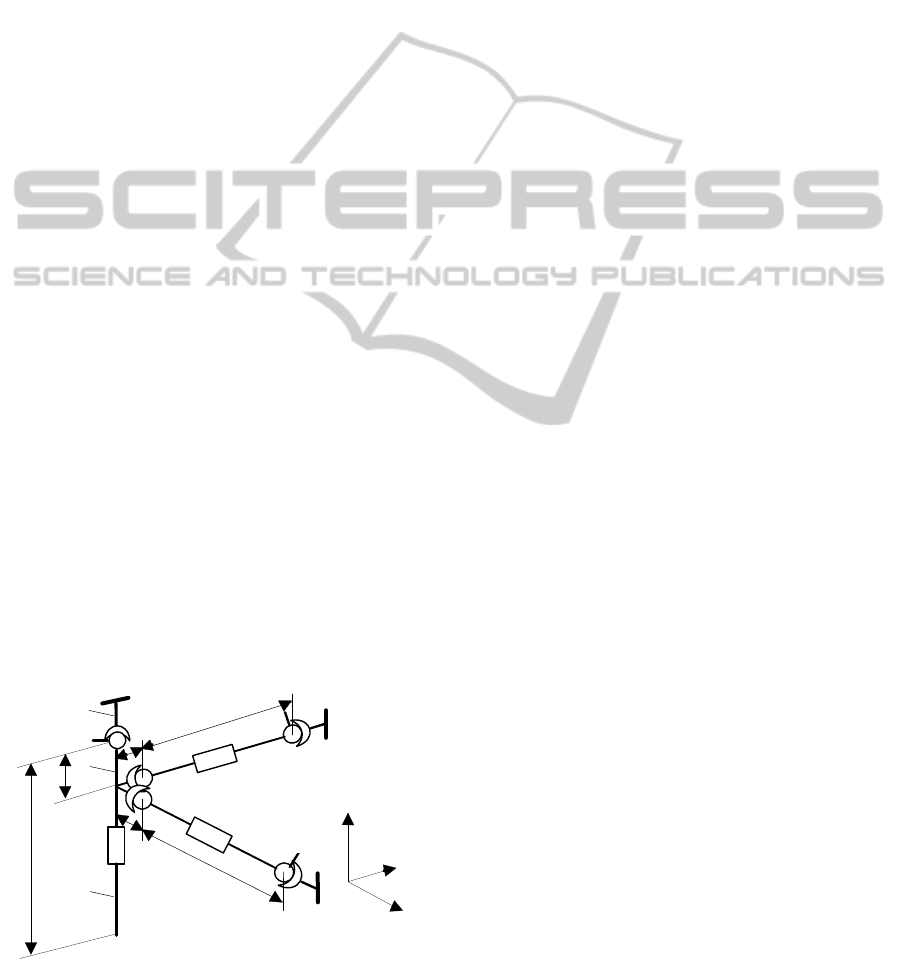
Figure 1: Kinematics scheme of serial-parallel manipulator
with 3 DOF.
serial-parallel structures capable of automatic cell
injection realization. We performed numeric
experimentation and estimation of the build up
models and approaches as well as experimental
investigation of the prototyped robotic system.
2 PSEUDO-RIGID-BODY MODEL
AND MODEL OF
PRELIMINARY TENSIONING
OF A PARALLEL STRUCTURE
WITH ELASTIC JOINTS
The studied micro-manipulator is a component of a
robot capable of performing automatic cell injection.
The aim of the micro-manipulator is to orientate and
to position the pipette according to the cells, as well
as to perform the necessary motions for cell
injection. The micro manipulator with a serial-
parallel structure is selected as shown in Fig. 1.
Here, pseudo rigid body model is used in order to
describe the compliant micromanipulator (Chakarov,
2009). It models all links as rigid bodies and the
elastic joints as revolute joints. Each 2 DOF elastic
joints are replaced by a 2 DOF universal joint with
torsion stiffness, as shown in Fig. 1.
Base 0, manipulator body 1, actuator А
3
with
working tool 2 and end- effector M form a serial
chain. The body 1 is linked with the base 0 by means
of 2 DOF universal joints J
3
. Actuators А
1
and А
2
are linked with the base 0 by means of 2 DOF
universal joints J
1
and J
2
, thus forming parallel
chains. The actuators are fixed to the body 1 via two
kinematics joints, which are 3 DOF spherical joints
(P3). Actuators А
1
and А
2
are modelled as 1 DOF
prismatic joints and the number DOF of the structure
come out to be h=3.
According to this model, generalized parameters
are accepted to be the parameters of the relative
motions in all joints of the structure - elastic and
non-elastic, presented by the vectors:
q = [q
1
, q
2
, q
3
]
T
,
(1)
a vector of the generalized coordinates in the joints
of the main serial chain with 3 DOF,
w = [w
11
, w
12
, w
21
, w
22
]
T
, (2)
a vector of coordinates in the passive universal joints
J
1
, J
2
of the parallel chains, and
l = [l
1
, l
2
, l
3
]
T
, (3)
a vector of coordinates in the actuator joints А
1
,А
2
,
and А
3
.
ICINCO2012-9thInternationalConferenceonInformaticsinControl,AutomationandRobotics
22

Let the linear coordinates of the end-effector M are
denoted as:
[]
T
321
X,X,XX =
.
(4)
The relation between the parameters of the basic
serial chain (1) and the parameters of the end-
effector (4) is known as a direct kinematics problem
for the serial chain
Ψ(q)X =
. This problem on the
level of velocities is presented by the equations:
qJX
&
&
=
,
(5)
where
[]
qXJ ∂∂=
is the (3 x 3) matrix of Jacoby.
In the parallel structure, each closed loop implies
the appearance of a connection between the
generalized parameters (1), (2), (3). These
connections are expressed by 6 scalar functions for
the structure including 2 parallel loops:
,0)l,w,q(
i
=Ψ
i=1,…,6. The differentiation of the
above equations, gives the matrix of partial
derivations
qwW ∂∂=
and
qlL ∂∂=
with size (4
x 3) and (3 x 3) and the relations between
generalized velocities:
qWw
&
&
=
(6)
qLl
&
&
= (7)
As the number of parameters (3) is equal to the DOF
h=3, these parameters can be selected as
independent ones. In equation (7) we have the
inverse relation:
lLq
1
&
&
−
=
.
(8)
Equations (5) and (8) allow determining the end-
effector velocities, while equations (6) and (8) - the
velocities of passive joints, as a function of the
velocities of the linear actuator joints
l
&
:
lJLX
1
&&
−
=
and (9)
lWLw
&
&
1−
=
. (10)
The displacements of the piezo-actuators are small
as compared to the link lengths. Therefore, the
micro-manipulator is almost configurationally
invariant and its matrix of partial derivations
J, L
and
W are assumed to be constants (Zhang, 2002).
The equations (8), (9), (10) give the relations
between the small displacements of the micro
actuators δl, the joints of the main serial chain
δq,
the end-effector δX and the passive joints δw:
lLq δ=δ
−1
, (11)
lJLX δ=δ
−1
and (12)
lWLw
1
δ=δ
−
.
(13)
A preliminary tensioning of the mechanical
micro-manipulation system is necessary in order to
eliminate the backlash of the kinematics joints and
to improve the performance of the piezo-actuators. It
is possible to use deformation in elastic joints to
achieve tension in closed structures resulting in
restoring forces. The following two approaches can
be used for tensioning of the manipulator:
1) Preliminary tensioning by means of assembly
translation along the axes of the linear driving joints,
which leads to deflection in all the system joints and
to tensioning of the actuators with a force
F
1
.
2) Preliminary tensioning by assembly deflections of
the basic serial chain elastic joints, which leads to
deflection only in these joints and to tensioning of
the actuators with a force
F
1
.
2.1 Model of Preliminary Tensioning
by Assembly Translation
along the Axes of the Driving Joints
The assembly displacement along the axes of the
driving joints denoted by the vector Δl
0
leads to
deflection in all the system joints, appearance of
resistant forces in the elastic joints and tensioning of
the actuators along their axis by force
F
1
. The
assembly displacement leads to elastic deformations
in the driving joints denoted by the vector
Δl
1.
The
assembly displacements
Δl
0
along the axes of the
drives and the working shifts of the drives
Δl
2
are
combined in the vector:
20
lll Δ
+
Δ
=
Δ
. (14)
The resultant displacement along the axes of the
driving joints after tensioning is equal to the sum:
1
lll Δ
−
Δ
=
δ
. (15)
This displacement is defined according to (11)
by means of deflections in the joins of the main
serial chain
q
δ
. The deflections of the end-effector
X
δ
according to (12) and the deflections in the
elastic joints of the parallel chains
wδ
according to
(13) are dependent on the resulting displacement
along the axes of the driving joints also (15).
The elastic deformations in the driving joints
Δl
1
define the resistant forces in them:
DevelopmentofaPiezo-actuatedRobotforCellInjection
23

1
lKF
ll
Δ
=
. (16)
The resulting displacements in the driving joints
(15) with the help of (13) define the resistant forces
in the elastic joins of the parallel chains:
wKF
ww
δ=
, (17)
and with the help of (11) define the resistant forces
in the elastic joints of the main chain:
qKF
qq
δ=
. (18)
K
l
, K
w
and K
q
above, are the matrixes of the axial
stiffness in the driving joints, in the elastic joints of
the parallel chains and in the elastic joints of the
main chain, respectively.
The elastic forces after system tensioning
establish static equilibrium:
F
q
+ W
T
F
w
= L
T
F
l
(19)
which according to (18), (17), (11), (13) and (15) is
defined by the equality:
l
T
w
T
q
FL]ll[WLKW]ll[LK =Δ−Δ+Δ−Δ
−−
1
1
1
1
(20)
After considering the inverse form of (16):
ll
FKl
1
1
−
=Δ
(21)
and modification of the above equality, the
displacements along the axes of the actuators are
defined as a function of the actuators forces:
ll
T
w
T
q
F]KL]WKWK[L[l
11 −−
++=Δ , (22)
where:
ll
T
w
T
q
BKL]WKWK[L =++
−− 11
(23)
is the adduced system compliance to actuator axes.
The desired tensioning force
F
l0
defines according to
(22) and (14) the necessary assembly displacement
along the axes of the driving joints
Δl
0
= Δl, when
the actuators are not
active (Δl
2
=0). The actuators
driving shifts Δl
2
after system tensioning with
displacement
Δl
0
lead to a force variation of the
actuators
F
l0
with the value of F
l2
defined by (22):
]FF[Bll
lll 2020
+
=
Δ+Δ
. (24)
The end-effector varies after manipulator tensioning
according to equalities (12), (15) and (14):
]lll[JLX
120
1
Δ−Δ+Δ=δ
−
, (25)
where
]FF[Kl
lll 20
1
1
+=Δ
−
. (26)
2.2 Model of Preliminary Tensioning
by Assembly Deflections of the
Basic Serial Chain Elastic Joints
The assembly displacement along the axes of the
elastic joints of the basic serial chain denoted by the
vector
Δq
0
leads to a deflection
in all the system
joints, appearance of resisting forces in the elastic
joints and tensioning of the actuators along their
axes with a force
F
1
. The raising elastic deformations
in the driving joints are denoted as in the previous
case with
Δl
1
, the working shifts of the actuators -
with Δl
2
and then the resultant displacements along
the axes of the driving joints are equal to the sum:
12
lll Δ−
Δ
=
δ
. (27)
These displacements lead to additional deformations
in the joints of the base chain according to (11).The
resultant joint displacements of the base chain after
their tensioning by the deformations
Δq
0
are:
qqq δ+
Δ
=
Δ
0
. (28)
The resistant torques which arise in the elastic joints
of the basic chain are defined by their stiffness
K
q
and deformations according to (28), (11) and (27):
]]ll[Lq[KF
qq 12
1
0
Δ−Δ+Δ=
−
. (29)
The resistant forces in the elastic joints of the
parallel chains are derived in the same way as in the
previous case according to equality (17) where the
equalities (13) and (27) are also valid. The static
system equilibrium (19) established after taking into
account (29) and (17) is defined by the value:
l
T
w
T
q
FL]ll[WLKW
]]ll[Lq[K
=Δ−Δ
+Δ−Δ+Δ
−
−
12
1
12
1
0
(30)
The upper equality allows definition of the pre-
tensioning in the basic joints, after taking into
account the dependence of the deformations in the
driving joints on the value of the driving forces (21):
]FKl[L
]FL]FKl[WLKW[K
q
ll
l
T
llw
T
q
1
2
1
1
2
11
0
−−
−−−
−Δ−
−−Δ−
=Δ
(31)
The desired tensioning force of the actuators F
l0
,
when they are not active (Δl
2
=0), defines according
to (31) the necessary assembly displacement along
the axes of the elastic joints of the basic serial chain
Δq
0.
The working actuator shifts Δl
2
after system
ICINCO2012-9thInternationalConferenceonInformaticsinControl,AutomationandRobotics
24
tensioning lead to force variation of the actuators
which according to (31) is defined by the equality:
]lL]WKWK[qK[
]LKL]WKWK[[F
w
T
qq
T
lw
T
ql
2
1
0
111
Δ++Δ∗
++=
−
−−−
.
(32)
The end-effector position varies at manipulator
tensioning and at performing of the work shift
according to the equalities (12), (27):
]ll[JLX
12
1
Δ−Δ=δ
−
. (33)
The raising elastic deformations in the driving joints
above are defined according to (21) and (32).
3 DESIGN AND NUMERICAL
EXPERIMENTATION OF THE
MICRO-MANIPULATOR
3.1 Design of a Robot System for Cell
Injection
A robot has been designed to perform automatic cell
injection (Kostadinov, 2009). The robot system
includes a macro-manipulator and a local micro-
manipulator. The macro-manipulator is scheduled to
insert the micro-manipulator with the injection
pipette in hand in the working zone. Here, the
biological cells on the range of 10-30 [μm] are
preliminary positioned in a matrix feeder. The aim
of the micro-manipulator is to orientate and to
position the pipette according to the cells, as well as
to perform the injection motions. The micro-
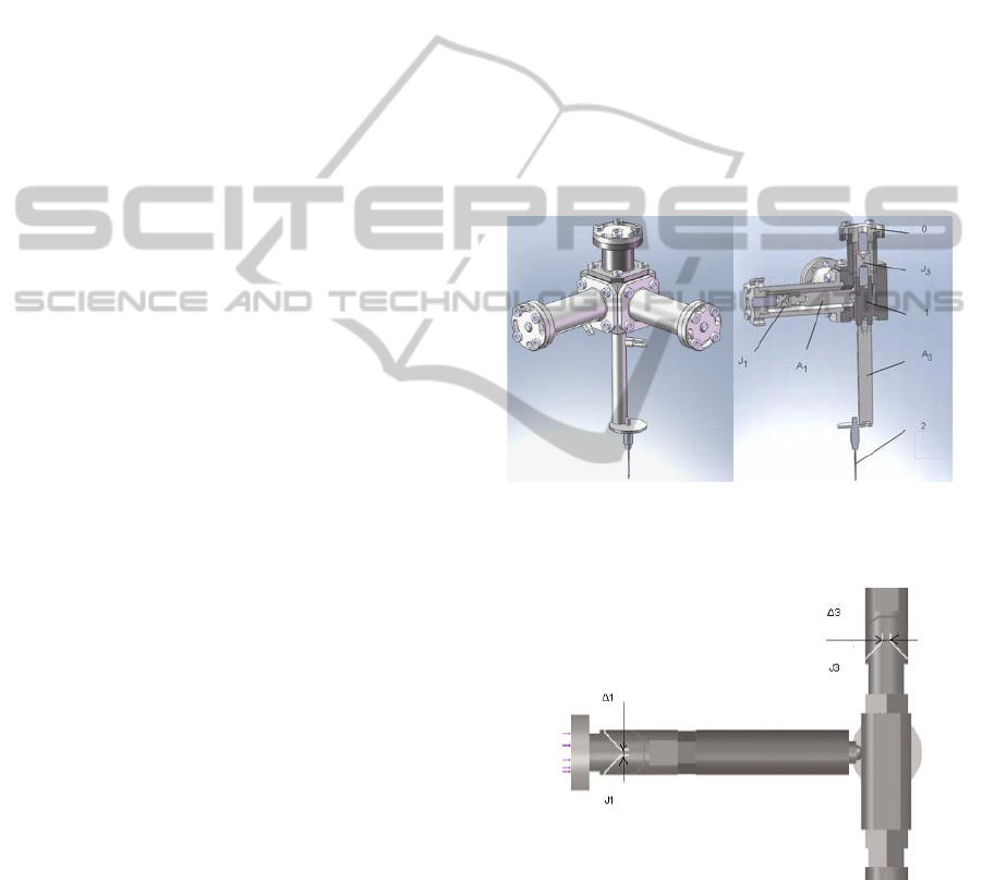
manipulator is designed as it is shown in the
simulation in Fig. 2. The manipulator body 1 is
linked to the base body 0 by means of an elastic joint
J
3
forming a serial chain. Actuators А
1
and А
2
are
located perpendicularly to the body 1 and they are
linked to the base 0 by means of elastic joints J
1
and
J
2
, thus forming parallel chains. The actuators are
fixed to the body 1 via spherical joints. Parallel
structure comprising actuators А
1
and А
2
performs
orientation motions, while the actuator А
3
performs
injection through the pipette 2 attached to it.
Piezoelectric stack actuators are chosen, hereafter
called piezo-actuators, for their smooth motion, high
accuracy, and fast response.
The joints J
1
, J
2
and J
3
are recognized as double
notched elastic beam joints. These joints allow by
means of a preliminary deformation to achieve pre-
tension of the piezo-actuators. The joint geometry
shown in Fig. 3 is accomplished with the help of
electro-discharge machining. This geometry allows
the desired low stiffness to be achieved in two
transverse mutually perpendicular directions of
bending and high stiffness in the rest non-motional
direction.
The main dimensions of the studied manipulator
according to Fig.1 are a
12
=a
22
=0.066[m],
a
11
=a
21
=0.007[m], b
1
=0.030[m], b
2
=0.180[m]. The
travel of the piezo-actuators used is as follow:
actuator A
3
:60 10
-6
[m]; actuators A
1
, A
2
: 30 10
-6
[m].
The actuators possess axial stiffness 27 10
6
[N/m]
and pushing force capacity 1000 [N]. The torque
limits of the actuators are 0.35 [N/m].
Forces
F
l
in the driving joints which tension
axially the actuators А
1
and А
2
are defined by the
stiffness of the elastic joints J
3
and J
1
, J
2
and by the
preliminary deflections according to the mentioned
above approaches.
Figure 2: Micro-manipulator: a) general view; b) cross
section. (0-base; 1 – coupling body; 2: glass pipette; A
1
-A
3
– piezo actuators; J
1
, J
3
– elastic joints).
Figure 3: Joints J
1
and J
3
performed as double notched
elastic beam joints.
The joint geometry presented in Fig. 3 allows the
desired angular stiffness to be achieved by means of
the width Δ variation of the most bending loaded
area. An assessment of the realized stiffness is
performed using FEA-based technique, applied to
the entire elastic system.
a)
b)
DevelopmentofaPiezo-actuatedRobotforCellInjection
25

The selected material of the elastic joint is
stainless steel (X2CrNi18-9) with Young’s modulus
E = 190 [GPa] and Yield strength σ=0.465 [GPa].
Joints J
1
, J
2
are selected with Δ
1
= Δ
2
= 0.0012 [m]
and joint J
3
with Δ
3
= 0.0020 [m] in developing
manipulator.
In result of the assessment, the value of join
angular stiffness is 91.3 [Nm/rad] for joints J
1
, J
2
and
340.3 [Nm/rad] for joint J
3
. The angular stiffness
matrices are defined as:
0][Nm/rad] 340.3; .3;340diagK
q
[=
; (34)
[Nm/rad] 91.3] 91.3; 91.3; diag[91.3;K
w
=
.
(35)
The linear stiffness matrix of actuators is defined as:
[N/m] 10 0] 27; diag[27;K
6
l
=
.
(36)
3.2 Numeric Experimentation
The matrix of partial derivations J, L and W, with
size (3x3), (3x3) and (4x3) are assumed to be
constant according the pseudo-rigid-body-model of
serial-parallel structures build up as presented in
chapter 2. A software application based on the
matrix equalities (11), (12), (13) and (19) is
developed to carry out numerical experiments.
Experiments are conducted of the preliminary joint
deflections for manipulator tensioning according to
the presented in chapter 2 approaches.
3.2.1 Mechanical Micro-manipulation
System Preliminary tensed According
to Approach 1
The value of forces in the driving joints is selected
to be 10% from the push force capacity of the
actuators used or 100 [N]. The vector of desired
actuator forces is defined as:
[N]0100100F
T
0l
];;[ −−=
.
(37)
Experiments are carried out when tension forces are
presented by vector (37), the stiffness of the elastic
joint J
3
is presented by matrix (34), the stiffness of
the elastic joints J
1
, J
2
-
by matrix (35) and the
stiffness of piezo-actuators A
1
, A
2
- by matrix (36).
Desired assembly deflection
in the driving joints,
which leads to deflection in all the system joints and
to tension of the actuators with a force 100
[N]
according to (22) is:
][];.;.[ m100707256704256l
6T
0
−
−−=Δ
.
(38)
Deformations
Δl
1
in the driving joints as a result
of the piezo-actuators’ compliance, shown by the
matrix (36), is defined by the equality (21):
][];.;.[ m10070337033l
6T
1
−
−−=Δ
.
(39)
Equation (15) allows determination of the
effective motion
in the driving joints, shown below:
][];.;.[ m100001253001253l
6T −
−−=δ
.
(40)
According to (12) and giving an account of (40),
the deflections of the end-effector are:
T
];.;.[
−
−−=Δ 000615180061518X
10
-6
[m]. (41)
For the effective motion
in the driving joints (40)
and selected angular stiffness, the torques of the
elastic joints J
3
and J
1
, J
2
according (11), (18) and
(13), (17) possess values:
T
q
086928692F ];.;.[−=
[Nm], (42)
T
w
0316003160F ];.;;.[ −= [Nm]. (43)
Torques (43) of the elastic joints J
1
, J
2
lead to
undesirable bending loading of the linear piezo-
actuators, but they are close to the torque limit of the
actuators 0.35 [N/m].
The tensioning force (37) varies at the working
shifts of the actuators in a manipulator tension state
according to (24). When maximal actuator shifts are
presented by the vector:
][];;[ m1003030l
6T
2
−
−−=Δ
.
(44)
Following (38) and (14), the actuator deflections are:
][];.;.[ m100704286704286l
6T −
−−=Δ
. (45)
The already changed tensioning force at maximal
actuator shifts according (24) is defined by the
vector:
][];.;.[ N0686111686111FF
T
2l0l
−−=+
. (46)
The effective shifts in the driving joints according to
(26) and (15) and the effective shift of the end-
effector according to (25) are:
][];.;.[ m100568282568282l
6T −
−−=δ
(47)
T
040816954081695X ];.;.[ −−=δ
10
-6
[m]. (48)
The difference
χ
between displacements (41) and
(48) forms the working range of the micro-
manipulator:
ICINCO2012-9thInternationalConferenceonInformaticsinControl,AutomationandRobotics
26
][];.;.[ m1060402177402177
6T −
=χ . (49)
3.2.2 Mechanical Micro-manipulation
System Preliminary tensed According
to Approach 2
Like the above case, experiments are carried out
when tension forces are presented by vector (37), the
stiffness of the elastic joint J
3
is presented by matrix
(34), the stiffness of the elastic joints J
1
, J
2
by matrix
(35) and the stiffness of piezo-actuators A
1
, A
2
by
matrix (36).
The preliminary displacements in the joints of
the basic chain, for actuator tensioning when they
are at starting position (Δl
2
=0), are defined by (31):
T
0
094489448q ];.;.[−=Δ
10
-3
[rad]. (50)
In the tensioned actuators elastic deformations arise
according as (21), which following (27) are equal to:
T
070337033l ];.;.[=δ
10
-6
[m]; (51)
and according as (12) define the deflections of the
end effector after tensioning of the actuators:
T
];.;.[
−
=δ 02182221822X
10
-6
[m]. (52)
The resistance torque in the elastic joint of the basic
chain after the system tensioning defined by (29) is:
T
q
000230023F ];.;.[−= [Nm]. (53)
When manipulator in a tensioned state performs the
maximal shifts of the actuator (44), the driving
forces change according to (32) and they are:
][];.;.[ N0686111686111F
T
l
−−=
. (54)
Elastic deformations of the actuators according to
(21) and (54) are:
][];.;.[ m10013641364l
6T
1
−
=Δ
. (55)
The resultant displacement along the axes of the
drives according to (27) is:
T
];.;.[l 08642586425 −−=δ
10
-6
[m] (56)
and the end-effector position according (12) is:
T−
−−=δ ]0;184.155;184.155[X
10
-6
[m]. (57)
The difference
χ
between positions (52) and (57)
forms the working range of the micro-manipulator:
][];.;.[ m1060402177402177
6T −
=χ
.
(58)
The performed experiments show that after
system tensioning deflections arise from the starting
position of the end-effector and at the first approach
these deflections are considerable (41), while at the
second one they are smaller (52). The end-effector
effective displacements at the same shifts of the
actuators in both approaches are equal (49 and 58).
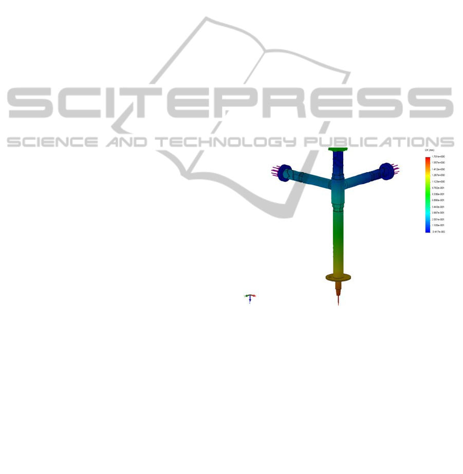
3.3 FEA Simulations
An additional experiment of the static load by
actuator tensioning was carried out using FEA
modelling as a function of a CAD system.
Simulations were conducted when tension forces are
attached at the end of motor loop A
1
, J
1
and A
2
, J
2,
respectively. Each motor loop is restricted at the end
as linear joints. All the system bodies are simulated
by means of the presented above material -
X2CrNi18-9, and the stack piezo-actuators are
modelled as an elastic joint possessing an axial
stiffness 27 10
6
[N/m]. The screen with the carried
out simulations is shown in Fig. 4.
Figure 4: Screen with effective displacements in X
direction.
3.3.1 Mechanical Micro-manipulation
System Preliminary tensed According
to Approach 1
The first experiment is carried out when the tension
forces have the values
F
11
=-100 [N] and F
12
=-100
[N]. Effective displacements at the end point of the
end-effector δx and δy
were reported by the CAD
system, respectively
in X and Y direction as it is
shown in Table 1.
The pointed out results are
averaged values from several simulations.
Effective
displacement δz in Z direction are very small (in
submicron range) and they are not object of the
present stuffy. Second experiment is carried out
when the tension forces have the values
F
11
=-
DevelopmentofaPiezo-actuatedRobotforCellInjection
27

111.686 [N] and F
12
=-111.686 [N].
The difference χ
between end-effector
displacements in the two shown above cases define
the working range of the micromanipulator in X and
Y direction χ
x
=184.10
-6
[m] and χ
y
=181.10
-6
[m]. In
the third experiment tension forces have the values
F
11
=-100 [N] and F
12
=-111.686[N]. Comparing the
last result with CAD results obtained one give
difference between end-effector displacements in X
and Y direction χ
x
=6.10
-6
[m] and χ
y
=175.10
-6
[m] as
it is shown in Table 1. The derived results show very
close parameter values to those calculated in chapter
3.2.1. We can conclude that because of axis
coupling, each of the actuators A
1
, A
2
influences the
displacements of both axes (X and Y). For example,
the displacement of X and Y direction in the second
experiment have a difference in the range of 3 μm
and displacement of Y direction and effective
displacement of X direction in the third experiment,
has a disturbance in a range of 6 μm.
Table 1: Effective displacements at the end-effector (1).
F
11
=-100[N
]
F
12
=-100 [N
]
F
11
=-111.686[N]
F
12
=-111.686 [N]
χ [m]
δx
[m]
-1517.10
-6
-1701.10
-6
184.10
-6
δy
[m]
-1518.10
-6
-1699.10
-6
181.10
-6
F
11
=-100
F
12
=-100
F
11
=-100
F
12
=-111
δx
[m]
-1517.10
-6
-1523 10
-6
6.10
-6
δy
[m]
-1518.10
-6
-1693 10
-6
175.10
-6
3.3.2 Mechanical Micro-manipulation
System Preliminary tensed According
to Approach 2
In this case the preliminary tensioning in the elastic
joints of the basic chain is presented with torques
(53) attached to the body 1 of the basic chain near to
the joint J
3
. Actuator loads are presented with forces
attached at the end of motor loop A
1
, J
1
and A
2
, J
2
,
respectively, similar to the experiments carried out
in the previous section, as shown in Fig. 4.
Simulations were conducted at values of the actuator
forces -100[N] or -111.686[N], similar to the
previous experiments. Effective displacements at
the end point of the end-effector δx and δy
in X and
Y direction and difference χ
between displacements
are shown in Table 2. The derived results show very
close parameter values with those calculated in
chapter 3.2.2. In this case, as well as in the previous
one, the simulations consider influence of each
actuator on the displacements along both axes (X
and Y), but this influence is smaller as the
deflections reach 2-3 μm.
Table 2: Effective displacements at the end-effector (2).
F
11
=-100
F
12
=-100
[N]
F
11
=-111.686
F
12
=-111.686
[N]
χ [m]
δx[m] 23.2 10
-6
-155.1 10
-6
178.3 10
-6
δy[m] 25.0 10
-6
-155.7 10
-6
180.7 10
-6
F
11
=-100
F
12
=-100
F
11
=-100
F
12
=-111
δx[m] 23.2 10
-6
25.4 10
-6
2.2 10
-6
δy[m] 25.0 10
-6
-154.7 10
-6
179.7 10
-6
4 EXPERIMENTAL SET-UP
& RESULTS
Some experiments proving the functionality of the
prototyped micromanipulator (Fig.5.) are performed.
An experimental set-up, consisting of an optical
system and a translational stage with 3 DOF, has
been built up (Fig. 6), to investigate the micro-
manipulator. The translational stage is used for
precise alignment of the micro-manipulator with
respect to the optical system and the image space
calibration. It contains 3 orthogonal translational
modules (M1÷M3) with integrated linear positioning
sensors possessing resolution of 0.1 µm. The micro-
manipulator is fixed to the translational stage
allowing precise positioning of its end-effector in the
image space of the optical system.
This optical system consists of a zoom imaging
lens with magnification of 2.5x - 10x at a constant
working distance of 35 mm. The camera sensor is
CMOS with 2592×1944 pixels and the pixel
dimensions are 2.2×2.2 µm
2
. The frame rate at full
resolution is 3 frames per second (fps) and at VGA –
30 fps. It defines how many times per second we can
inspect the system. This parameter together with the
computational power and the algorithm effectiveness
define the vision control speed (
Liu, 2006). If we
have efficient numerical algorithms and fast
computer system, the vision control is limited only
by the camera frame rate (Jin, 2005). The used
digital image correlation technique shows that the
minimal displacement resolution obtained
experimentally is 50 nm (Shulev, 2011).
The first approach for manipulator tensioning is
experimented. Each piezo-actuated axis of the
micromanipulator was tested separately, thus
investigating the working space of the manipulator.
The obtained result for axis X actuated by piezo-
actuators A1 is presented in Fig. 7. Results show the
motion range along the axes X and Y, i.e.: χ
x
= χ
y
=
226 μm. The result is determined by the used glass
pipette length. To measure repeatability, the piezo-
ICINCO2012-9thInternationalConferenceonInformaticsinControl,AutomationandRobotics
28
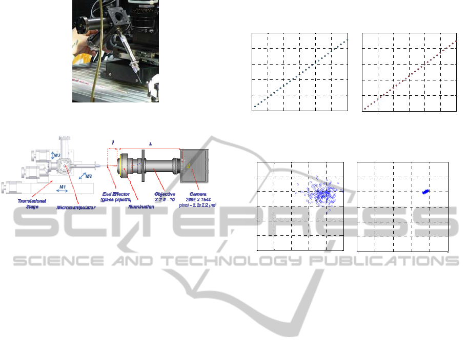
Figure 5: Prototype of micromanipulator with 3 DOF.
Figure 6: Scheme of the experimental set-up.
actuators with open loop control have been set at a
given position 200 times and the end-effector
position was measured. Experiments are conducted
separately for manipulator tensed according
approach 1 and approach 2 and without hysteresis
compensation. The obtained results for both
approaches are shown in Fig. 8 a) and b). The
working shifts of the actuators A1 and A2 are given
equal to 1
μm. It was found that end-effector
maximal positioning error is in a range of (3-5)
μm
for approach 1 and (0-1)
μm for approach 2.
5 CONCLUSIONS
In this paper a model and experiments of compliant
robots with piezo-actuators for micro- and nano-
manipulations are presented. A kinematics model of
serial-parallel structures is presented. Pseudo rigid
body approach is used, where the elastic joints are
modelled as revolute joints.
Methods for tension of serial-parallel structures
with elastic joints are developed in order to
eliminate backlashes, to diminish hysteresis, and to
improve the performance of the piezo-actuators.
Two design approaches are proposed. First
approach ensures preliminary tensioning by
assembly translation along the axes of the driving
joints. Second approach ensures preliminary
tensioning by assembly deflections of the basic
serial chain elastic joints.
The new 3 DOF piezo-actuated micro-
manipulator designed to perform cell injection is
presented. Numerical experiments are done for the
manipulator tensioning.
0 5 10 15 20 25 30
0
50
100
150
200
250
A1 [um]
X
[
um
]
0 5 10 15 20 25 30
0
50
100
150
200
250
A2 [um]
Y [um]
Figure 7: Experimental results of the range of motion for
axes: a) X actuated by actuator A1; b) Y actuated by A2.
0 2 4 6 8 10
0
2
4
6
8
10
12
X
[
um
]
Y
[
um
]
0 2 4 6 8 10
0
2
4
6
8
10
12
X [um]
Y [um]
Figure 8: End-effector repeatability measurement:
a) approach 1; b) approach 2.
An estimation of the manipulator mechanical
parameters for different approaches is carried out.
The performed experiments show that after system
tensioning deflections arise from the starting
position of the end-effector. At the first approach,
these deflections are considerable, and at the second
one they are smaller. At both approaches, the end-
effector effective displacements at the same shifts of
the actuators are equal.
Simulations of the manipulator with elastic joints
are carried out using FEA based function of a CAD
system. The simulations performed show that the
motion of one axis interferes with the other axis and
this influence is bigger at the first approach for pre-
tensioning and smaller at the second one.
The proposed approaches for manipulator
tensioning are experimented on the real manipulator
prototype. Experimental investigation of the
prototyped robotic system is realized by a digital
image correlation technique. Obtained results of
experiments testing of the prototyped micro-
manipulator on the range of motion along the axes X
and Y is χ
x
= χ
y
= 226 μm. The repeatability of the
end-effector position is obtained for the case with
open loop control system and without compensation
of hysteresis. It was found for this case that maximal
positioning error for the first approach is (3-5)
μm
and for the second one - (0-1)
μm.
Further investigations and experiments are under
a)
b)
a)
b)
DevelopmentofaPiezo-actuatedRobotforCellInjection
29

consideration for closed loop control of the X and Y
axes including hysteresis compensation method for
piezo-actuators based on the discrete Preisach model
(Marinov, 2009), as well as for injector pipette in Z-
axis in order to realize the successful cell injection.
ACKNOWLEDGEMENTS
The authors gratefully acknowledge the support for
this work through the project SpeSy-MiNT funded
by the Bulgarian National Science Foundation under
the Contract Nr. DO 0171/16.12.2008.
REFERENCES
Kasper, R. M.Al-Wahab, 2004. Mechanically Structured
Piezoelectric Actuators, 9
th
Int. Conf. on New
Actuators, Bremen, Germany, pp.68-71.
Pernette, E, S. Henein, I. Magnani and R. Clavel, 1997.
Design of Parallel Robots in Microrobotics, Robotica,
vol.15, pp.417-420.
Yong, Y. K., Tien-Fu Lu, 2008. The Effect of the
Accuracies of Flexure Hinge Equation on the Output
Compliances of Planar Micro- motion Stages,
Mechanism and Machine Theory 43, pp.347-363.
Chih-Liang Chu, Sheng-Hao Fan, 2006. A Novel Long-
travel Piezoelectric- driven Linear Nanopositioning
Stage, Precision Engineering 30, pp. 85-95.
Li Y. and Q. Xu, 2011. A Totally Decoupled Piezo-Driven
XYZ Flexure Parallel Micropositioning Stage for
Micro/Nanomanipulation, IEEE Transactions On
Automation Science And Engineering, Vol. 8, No. 2.
Zhang, W., Zou, J., Watson, L., Zhao, W., 2002. The
constant- jacobian method for kinematics of a three
DOF planar micro-motion stage, Journal of Robotic
Systems 19(2), pp.63–72.
Pham, H., Chen, I., 2005. Stiffness modeling of flexure
parallel mechanism, Precision Engineering 29, pp.
467–478.
Lu Z., X. Zhang, C. Leung, N. Esfandiari, R. Casper, Yu
Sun, 2011. Robotic ICSI (Intracytoplasmic Sperm
Injection), IEEE Transactions on Biomedical
Engineering, vol. 58, No. 7, pp.2102-2108.
Tang, H., Y. Li, J. Huang, Q. Yang, 2012. Design and
Assessment of a Flexure-Based 2-DOF
Micromanipulator for Automatic Cell Micro-Injection,
Advanced Materials Res., vol. 457-458, pp. 445-448.
Chakarov, D., K. Kostadinov, T. Tiankov, 2009. Model
and approaches for tension of parallel structures with
elastic joints for micro and nano manipulators, Int.
Conf. on Informatics in Control, Automation and
Robotics, Milan, Italy, 2-5 July, Vol.2, pp.135-140.
Kostadinov, K., D. Chakarov, T. Tiankov, Fl. Ionescu,
2009. Robot for Micro and Nano Manipulations, BG
Patent, Reg. No 110432/28.07.2009.
Liu, C., W. T. Freeman, R. Szleski, and S. B. Kang, 2006.
“Noise Estimation from a single image”, IEEE
Computer Vision and Pattern Recognition, vol. 1, pp.
901-908.
Jin, H. and H. A. Bruck, 2005. Theoretical development
for point wise digital image correlation, Optical
Engineering, vol. 44, no. 1, pp. 1-14.
Shulev A., K. Kostadinov, T. Tiankov, and I. Roussev,
2011. Optical Positioning Control of a 3D Micro-
manipulator, Proceedings of 3M-NANO International
Conference on Manipulation, Manufacturing and
Measurement on the Nanoscale, Changchun, China,
29.08-02.09.2011, paper 108, p.4.
Marinov M., 2009. “Method for Hysteresis Compensation
in Piezo-actuators Using Discrete Preisah Model”
Journal Mechanics of the Machines, year XVII, vol.
80, ISSN, 0861-9727.
ICINCO2012-9thInternationalConferenceonInformaticsinControl,AutomationandRobotics
30
