
Contact-free Magnetic Clutch Applied
for Flywheel Cell System
Nan-Chyuan Tsai and Hong-Seng Aw
Department of Mechanical Engineering, National Cheng Kung University, 70101, Tainan City, Taiwan
Keywords: Servo Gap-Retained Mechanism, Hybrid Magnetic Actuator, Feedback-Linearized Sliding Mode Control.
Abstract: A TDOF (Two Degrees of Freedom) Servo Gap-Retained Mechanism (SGRM) is proposed and verified by
experiments. It consists of a flywheel and an Intelligent Posture Tracking System (IPTS). The flywheel is
regarded as the tracking objective of the IPTS. The IPTS is mainly composed by an intelligent disc and two
pairs of Hybrid Magnetic Actuators (HMAs). The posture of the intelligent disc is controlled by the
magnetic forces induced by the HMAs to retain a constant gap with respect to the eccentric flywheel. Since
the HMA is highly nonlinear, a Feedback-Linearized Sliding Mode Control (FLSMC) is synthesized to
account for system parameter nonlinearities. The proposed SGRM is part of the flywheel cell system. When
the MGU (Motor/Generator Unit) in flywheel cell operates at idle mode, the shaft of flywheel will be
separated from MGU in order to avoid the energy loss of the flywheel by the back EMF induced by the
magnetic field of MGU. The shaft of flywheel and MGU still need to maintain synchronous power
transmission so that a contact-free clutch has to be equipped. The role of SGRM in a flywheel cell is to
ensure the centerline of the flywheel properly is aligned with the magnetic clutch. Intensive experimental
simulations are undertaken to verify the feasibility of the proposed SGRM and FLSMC.
1 INTRODUCTION
Recently, due to the green and diverse types of
energy gradually emphasized, Flywheel Energy
Storage System (FESS) has become a popular choice
because of its inherent properties of free pollution
and fairly short rise time. In general, the flywheel
cell is equipped with a Motor-Generator Unit
(MGU) in a vacuum chamber. However, the kinetic
energy loss due to the interaction (i.e., back EMF
effect) between flywheel shaft and MGU is the most
serious issue and has to be avoided. This problem
can be solved by separating the MGU from the
flywheel via a non-contact electromagnetic clutch
which can transmit required torque, without physical
contact, between MGU and flywheel. Most
importantly, for high-efficient power transmission,
the gap between the active rotor, connected to the
MGU, and the counter-part, passively driven by the
active rotor, at the electromagnetic clutch has to be
retained as constant all the time (Li, 2009). In other
words, the SGRM is the key to the electromagnetic
clutch being able to align the shaft of flywheel with
the centerline of MGU.
A SGRM with two pairs of Hybrid Magnetic
Actuators (HMAs) is proposed and verified by
experiments. In order to achieve high-precision
motion, a control strategy with superior servo
capability to incorporate with the nature of magnetic
actuators is synthesized. Each individual HMA
consists of a permanent magnet to counterbalance the
gravity of the intelligent disc and an electromagnet to
control the posture of the intelligent disc. Since the
electromagnetic system is highly nonlinear, a
Feedback-Linearized Sliding Mode Control (FLSMC)
is proposed to account for the system nonlinearities,
uncertainties and unmodeled dynamics. Finally,
intensive computer and experimental simulations are
undertaken to validate the feasibility of the proposed
SGRM and FLSMC.
2 OPERATION PRINCIPLE
The schematic diagram of the proposed Servo Gap-
Retained Mechanism (SGRM) IS shown in Fig. 1.
The SGRM mainly consists of an induction motor, a
flywheel, an intelligent disc and four identical
Hybrid Magnetic Actuators (HMAs). The intelligent
disc can be adjusted to keep constant gap with
368
Tsai N. and Aw H..
Contact-free Magnetic Clutch Applied for Flywheel Cell System.
DOI: 10.5220/0003994903680376
In Proceedings of the 9th International Conference on Informatics in Control, Automation and Robotics (ICINCO-2012), pages 368-376
ISBN: 978-989-8565-21-1
Copyright
c
2012 SCITEPRESS (Science and Technology Publications, Lda.)

respect to the spinning eccentric flywheel which can
tilt both about X- and Y-axes and whose center of
mass can translate along X-, Y- and Z-axes. The
flywheel, which is assumed as a rigid body, is
connected to the induction motor by a flexible
coupling. The spinning speed of the flywheel is
governed by the induction motor. The intelligent
disc, which is also a rigid body, is equipped beneath
the flywheel with a nominal gap. The universal joint
is employed as the pivot of the intelligent disc such
that the intelligent disc can conduct 3-DOFs
rotations, i.e., yaw, pitch and spin. All the centroids
of the induction motor, the flywheel, the intelligent
disc and the universal joint are aligned vertically
before the flywheel starts to spin. In addition, the
flywheel is eccentric so that the tilting about X- and
Y- axes occurs. Four identical HMAs are located
ninety degrees apart under the intelligent disc to
control its posture. Each individual HMA unit
consists of a Permanent Magnet (PM) and an
Electromagnet (EM) to cooperate to generate a
resultant magnetic force to adjust the posture of the
intelligent disc, as shown in Fig. 2. It is noted that
the merits of employing HMAs, in which the same
wire is wound around the same pair, not only reduce
the number of power amplifiers but also
considerably enhance the system stiffness of the
SGRM. Significantly, adequate system stiffness can
improve the bandwidth such that superior transient
performance and servo capability of gap retaining by
the intelligent disc can be, to some extent, ensured.
On the other hand, four gap sensors, two for the
flywheel and the others for intelligent disc, are used
to acquire the real-time data of tilting of the flywheel
and the intelligent disc.
The dynamics of the SGRM can be divided into
two parts. One is the flywheel system, which consists
of the flywheel itself and the flexible coupling. The
other is the Intelligent Posture Tracking System
(IPTS), which consists of the intelligent disc and the
HMAs. The posture of the flywheel, in fact, is the
target of tracking by the intelligent disc. Therefore,
for the purpose of posture tracking, the dynamics of
the flywheel system has to be modeled on the base of
the displacements in X- and Y-axes.
The reference frames of the flywheel are shown
in Fig. 3. The coordinate
},,{ ZYX denotes the
inertial reference frame and
},,{ CBA the frame
attached on the flywheel.
S is the centroid of the
flywheel,
P the center of mass of the flywheel, e
the eccentricity and
θ
the argument of the eccentric
mass.
f
γ
,
f
β
and
φ
are the yaw angle, pitch angle
and spin angle of the flywheel about X-, Y- and Z-
axes respectively. Since the vertically translational
stiffness of the flexible coupling is relatively high,
the translational displacement of the flywheel in Z-
axis direction is relatively insignificant and can be
neglected. The superscript “f ” is referred to the
flywheel.
f
m is the mass of the flywheel.
f
R
I and
f
P
I are the transverse mass moment of inertia and
the polar mass moment of inertia of the flywheel
respectively.
φ
&
=Ω is the rotational speed of the
flywheel.
θξ
sine
f
= and
θη
cose
f
= are the
projections of the eccentricity onto A- and B-axes
respectively. By Lagrange’s method, the equations
of motion of the flywheel can be obtained as
follows:
f
f
P
f
f
R
II
γβ
&
&&
Ω=
(1a)
f
f
P
f
f
R
II
βγ
&
&&
Ω−= (1b)
tmtmvm
ffffff
ΩΩ+ΩΩ= cossin
22
ζη
&&
(1c)
tmtmwm
ffffff
ΩΩ−ΩΩ= sincos
22
ζη
&&
(1d)
Because the dynamics of the flywheel system is
directly influenced by the flexible coupling, the
dynamics of the flexible coupling is analyzed by
Timoshenko beam theory and modeled by Finite
Element Method (FEM). A finite element of the
flexible coupling is shown in Fig. 4. An element of
the flexible coupling consists of two nodes. Each
node has four DOFs. The translational
displacements of an element of the flexible coupling
can be described as
),( tsw and ),( tsv in X- and Y-
axes directions respectively and the rotational
displacements are
),( ts
γ
and ),( ts
β
respectively.
The displacements of an element of the flexible
coupling can be constructed as follows:
)()(
),(
),(
ts
tsv
tsw
T
e
qΨ=
⎥
⎦
⎤
⎢
⎣
⎡
(2a)
)()(
),(
),(
ts
ts
ts
T
e
qΦ=
⎥
⎦
⎤
⎢
⎣
⎡
β
γ
(2b)
where the superscript “
T
” denotes transpose
operator.
s
is the axial position along an element, t
the time instant and
],,,[
821
qqq
e
L=q the element
displacement vector of the flexible coupling.
Ψ and
Φ are the mode shape functions.
Eventually, the equations of motion of the flywheel
system with flexible coupling can be constructed by
combining Eq. (1) with Eq. (2) as follows:
tt
cs
Ω+Ω=+Ω++ cossin)( hhqKqGqNΜ
&&&
(3)
where
M , N , G and K are the translational mass
Contact-freeMagneticClutchAppliedforFlywheelCellSystem
369

matrix, the rotational mass matrix, the gyroscopic
matrix and the system stiffness matrix of the
flywheel system respectively.
s
h and
c
h are the
eccentric forces induced by eccentricity. Details of
matrices
f
M ,
f
N ,
f
G ,
f
s
h and
f
c
h are defined in
the Appendix.
The intelligent disk has to follow the motion of
the flywheel in the directions of pitch and yaw. To
sum up, the equations of motion of the intelligent
disc can be described as follows:
()
()
γ
γγβ
γγβγ
MI
II
dddd
P
dddd
R
dd
R
=−
+
cossin
cossin
2
2
&
&
&&
(4a)
β
γγγβ
γγγβ
γβγβ
MI
I
II
ddddd
P
ddddd
R
ddd
P
ddd
R
=+
−
+
cossin2
cossin2
sincos
22
&
&
&
&
&&&&
(4b)
where
γ
M and
β
M are the torques induced by
the HMAs in the
γ
- and
β
-axes ( i.e., yaw and
pitch) respectively. The superscript “
d ” is referred
to the intelligent disk.
The physical parameters of the flywheel system
and the IPTS are listed in Tables 1 and 2
respectively. In order to reveal the nature of the
flywheel dynamics, the open-loop of the gap-
retained mechanism is examined at first. The time
response and frequency response of the yaw angle of
the flywheel are shown in Figs. 5 and 6 respectively.
As shown in Fig. 6, the first natural frequency of the
flywheel system, 13.73 Hz, is the fundamental
frequency due to the flexible coupling, and the
second, 16.79 Hz, is the first natural frequency of the
rotational motion of the flywheel. It is evident that
the first two frequencies of the flywheel system are
very close to each other. Therefore, the amplitude of
the time response, shown in Fig. 5, is slowly varying
as time is running. The frequency of the time
response is simplythe average of those two
frequencies. That is, it is the so-called beat
phenomenon (Thomson, 1997) which is inherently
embedded in the flywheel system.
It is evident from Eq. (3) that the HMA is a
highly nonlinear system. Theoretically, the magnetic
force of the HMA is proportional to the square of the
applied current and inverse square of the air gap. In
addition, an electromagnetic actuator is inherently an
unstable system (Tsai, 2010). Therefore, a closed-
loop control is absolutely necessary to stabilize the
unstable system.
3 CONTROL STRATEGY
The proposed control strategy is based on feedback
linearization theory (Matas, 2008) and synthesized
via sliding mode approach (Shankar, 1999). The
main concept of feedback linearization is to simplify
the nonlinear system by means of feedback so that
an approximate linear relation between the inputs
and outputs of the closed-loop system can be
constructed. Finally, a Sliding Mode Control (SMC)
loop is synthesized to ensure the desired
performances.
The dynamics of the IPTS can be rewritten as
follows:
uxκxχx ))(())(( tt +=
&
(5a)
))(( tx
ϑ
=y
(5b)
where
[]
[]
T
dddd
T
xxxx
ββγγ
&
&
=
=
4321
x
(6a)
[]
T
4321
χχχχ
=χ
(6b)
⎥
⎥
⎥
⎥
⎦
⎤
⎢
⎢
⎢
⎢
⎣
⎡
+
=
1
2
1
2
sincos
1
0
0
1
xIxI
I
d
P
d
R
d
R
κ
(6c)
[]
T
MM
βγ
=u (6d)
[]
T
yy
21
=y (6e)
[]
T
xx
31
=
ϑ
(6f)
21
x=
χ
(6g)
()
11
2
42
cossin xxx
I
II
d
R
d
R
d
P
−
=
χ
(6h)
43
x=
χ
(6i)
]cossin)(2[
sincos
1
1124
1
2
1
2
4
xxxxII
xIxI
d
P
d
R
d
P
d
R
−•
+
=
χ
(6j)
where
1
x and
3
x are the pitch and yaw of the
intelligent disk respectively while
2
x and
4
x are the
pitch rate and yaw rate respectively.
x denotes the
state vector of the intelligent disk dynamics,
χ the
nonlinear system dynamics,
κ
the input matrix, u
the system input vector,
y
the measurement vector
and
ϑ
the output vector. By input-output
linearization, the system output has to be
differentiated, with respect to time, until it is
explicitly related to the system input (Matas, 2008),
ICINCO2012-9thInternationalConferenceonInformaticsinControl,AutomationandRobotics
370

i.e.,
uxΓxΛy )()(
)(
+=
δ
(7)
where
[]
T
yy
21
)(
&&&&
=
δ
y
(8a)
⎥
⎥
⎥
⎥
⎥
⎦
⎤
⎢
⎢
⎢
⎢
⎢
⎣
⎡
−•
+
−
=
]cossin)(2[
)sincos/(1
cossin
)(
)(
1124
1
2
1
2
11
2
4
xxxxII
xIxI
xxx
I
II
d
P
d
R
d
P
d
R
d
R
d
R
d
P
xΛ (8b)
⎥
⎥
⎥
⎥
⎦
⎤
⎢
⎢
⎢
⎢
⎣
⎡
+
=
1
2
1
2
sincos
1
0
0
1
)(
xIxI
I
d
P
d
R
d
R
xΓ (8c)
δ
is the order of the differential Eq. (6). Because
the target of the SGRM is to adjust the yaw angle
and pitch angle of the intelligent disc to track those
of the flywheel, the sliding hyperplane can be
defined as follows:
][)(
31
ΣΣ=tΣ (9)
where
0
11011111
=
∫
++=Σ dteee
α
α
&
(10a)
0
33033133
=
∫
++=Σ dteee
α
α
&
(10b)
where
f
xe
γ
−=
11
and
f
xe
β
−=
33
. The coefficients
11
α
,
10
α
,
31
α
and
30
α
are the design parameters
and all positive. Based on the sliding hyperplane, the
composite control can be constructed as follows:
()
()
⎟
⎟
⎠
⎞
⎜
⎜
⎝
⎛
⎥
⎥
⎦
⎤
⎢
⎢
⎣
⎡
Σ
Σ
−
⎥
⎥
⎦
⎤
⎢
⎢
⎣
⎡
Λ
Λ
−
⎥
⎥
⎦
⎤
⎢
⎢
⎣
⎡
−−
−−
=
⎥
⎥
⎦
⎤
⎢
⎢
⎣
⎡
−
33
11
3
1
330331
110111
1
Sat
Sat
ee
ee
M
M
d
d
ρ
ρ
ααβ
ααγ
β
γ
&
&&
&
&&
Γ
(11)
where
⎥
⎥
⎥
⎥
⎥
⎥
⎥
⎦
⎤
⎢
⎢
⎢
⎢
⎢
⎢
⎢
⎣
⎡
−•
+
−
=
⎥
⎥
⎦
⎤
⎢
⎢
⎣
⎡
Λ
Λ
]cossin)(2[
sincos
1
cossin
)(
1124
1
2
1
2
11
2
4
3
1
xxxxII
xIxI
xxx
I
II
d
P
d
R
d
P
d
R
d
R
d
R
d
P
(12)
1
ρ
and
3
ρ
are the reaching factors and both
positive. “
Sat ” is the saturation function.
It is noted that since the proposed control
strategy is based on feedback linearization
technique, the uncontrolled states of the system,
which are referred to as the internal dynamics or
zero dynamics consistent with the constraint
0)( =ty , must be ensured to be bounded (Matas,
2008). If the eigenvalues of the linearization of
internal dynamics lie in left half plane of the
complex plane, the system is locally exponentially
minimum phase. That is, the internal dynamics is
bounded. In other words, the stability of controlled
states, i.e.,
1
x and
3
x , can be ensured by Eq. (11)
and Eq. (12). Once the eigenvalues of the
linearization of internal dynamics all lie in left half
plane of the complex plane, the stability of entire
system can be ensured.
4 EXPERIMENTAL RESULTS
The test rig of the SGRM is shown in Fig. 7. The
experiments are undertaken under the interface
module DS1104 by dSPACE and the environment by
Matlab/Simulink. The proposed FLSMC is
implemented using TMS320F240 DSP with 10 kHz
sampling frequency. Two gap sensors, Model KD-
2300 by KAMAN Instrumentation Corporation, are
employed to acquire the angular displacements of
the flywheel at the top side about X- and Y-axes.
The other two are used to measure the angular
displacements of intelligent disc below the
intelligent disc about X- and Y-axes. Two sets of
power amplifiers are also employed to implement
the control commands for the intelligent disc to
retain constant gap with respect to the eccentric
flywheel. The commands at digital controller are
processed by D/A (Digital to Analog) converter at
first. Since the power amplifiers are of the
transconductance type, it becomes simpler to just
control the applied current at magnetic actuators
directly. The power amplifier, Chip PA12A by
APEX, has wide bandwidth and superior linearity
and is employed as the voltage-current converter in
this work. The output current of PA12A is allowed
up to 15 A, which is large enough to energize the
electromagnets at HMAs.
Under FLSMC law, the time response of tilt
displacement (i.e., yaw angle) of the proposed
SGRM is shown in Fig. 8. The rotational speed of
the induction motor is preset at 2400 RPM and the
wobbled frequency of the flywheel is about 80 Hz.
After 0.07 sec, the tracking error, shown in Fig. 9, is
reduced to below 5% of the amplitude of the tilt
displacement. It is observed that the proposed
SGRM possesses superior transient response and
servo capability upon tracking of the eccentric
flywheel. In addition, the applied current at HMAs
is shown in Fig. 10. Because the HMA is designed
to include PM (Permanent Magnet), the bias current
for the HMA to counterbalance the gravity of the
intelligent disc is almost negligible. Therefore, the
amplitude of applied current for EMs
(Electromagnets) is only about 0.6 A. The
Contact-freeMagneticClutchAppliedforFlywheelCellSystem
371

experimental setup and result for the flywheel
discharge ( i.e., from kinetic energy to electric
energy) are shown in Fig. 11 and Fig. 12
respectively.
5 CONCLUSIONS
An innovative intelligent disc, with magnetic
actuators, to retain a constant gap with respect to a
spinning eccentric flywheel which spins, tilts and
wobbles. The magnetic actuators are designed to
include both EMs (Electromagnets) and PMs
(Permanent Magnets) so that most of the gravity of
the intelligent disc is counterbalanced by PMs. A
Feedback-Linearized Sliding Mode Control
(FLSMC) is synthesized to account for system
nonlinearities or unmodeled dynamics. The entire
mechanism, excluding the flywheel, is named as a
SGRM (Servo Gap-Retained Mechanism). The
SGRM is verified both by computer simulations and
experiments. Not only is the system stiffness greatly
enhanced, but also the number of power amplifiers
and energy consumption are both reduced. It is
shown that the gap between the flywheel and the
intelligent disc can be retained. The corresponding
settling time is less than 0.07 sec and the worse
tracking error is below 5%. The required control
current at the EMs is always less than 0.75 A. From
the experimental result, even though the upper
bound of system parameters uncertainty is up to
15%, FLSMC is capable to stabilize the gap-retain
dynamics and sustain excellent performance.
ACKNOWLEDGEMENTS
This research was partially supported by National
Science Council (Taiwan) with 3-year Grant 98-
2221-E-006-184-MY3. The authors would like to
express their appreciation.
REFERENCES
Li, Y., Xing, J., Han, S., Lu, Y., 2009. Principle and
simulation analysis of a novel structure non-contact
electromagnetic clutch, The 12th Int. Conf. Electr.
Mach. Syst.
Matas, J., Castilla, M., Guerrero, J. M. de Vicuña, L. G.
Miret, J., 2008. Feedback linearization of direct-drive
synchronous wind-turbines via a sliding mode
approach, IEEE Trans. Power Electron. 23(3)
pp.1093-1103.
Shankar, S., 1999. Nonlinear Systems: Analysis, Stability,
and Control, Springer, New York.
Thomson, W. T., Dahleh, M. D., 1997. Theory of vibration
with applications, Prentice Hall, 1997.
Tsai, N.-C., Chiang, C.-W., 2010. Spindle position
regulation for wind power generators, Mech. Syst.
Signal Process. 24(3) pp. 873-889.
ICINCO2012-9thInternationalConferenceonInformaticsinControl,AutomationandRobotics
372

APPENDIX
Table 1: Parameters of Gap-Retained Mechanism.
Parameter Notation Numerical Value Unit
Mass of Flywheel
d
m 0.9861 kg
Eccentric Angle
θ
0.7854 rad
Eccentric Distance e 12e-3 m
Polar Mass Moment of Inertia
(Flywheel)
dp
I
0.0111
2
kgm
Transverse Mass Moment of
Inertia (Flywheel)
dR
I 0.0080
2
kgm
Cross-Section Area of Coupling
A
3.2673e-4
2
m
Length of Coupling
L
50e-3 m
Density of Coupling
ρ
1280
3
m
Kg
Young’s Modulus
E
1e6
2
m
N
Shear Modulus
s
G 1250e3
2
m
N
Shear Factor
s
K
0.9 Dimensionless
Polar Mass Moment of Inertia
(Coupling)
ep
I
ˆ
1.4156e-4
2
kgm
Transverse Mass Moment of
Inertia (Coupling)
eR
I
ˆ
8.1660e-5
2
kgm
Area Moment of Inertia
(Coupling)
em
I 1.1060e-7
4
m
Rotational Speed of Motor Ω 1000 rpm
Table 2: Parameters of IPTS.
Parameters Notations Numerical Values Unit
Transverse Mass Moment of Inertia of
Intelligent Disc
d
R
I
0155.0
2
mKg −
Polar Mass Moment of Inertia of Intelligent Disc
d
P
I 0078.0
2
mKg −
Lengths from Pivot of Intelligent Disc to HMAs
β
γ
ll , 092.0 m
Area of Air Gap
G
A
4
108
−
×
2
m
Area of PM
P
A
4
105.4
−
×
2
m
Air Gap
A
G
3
103
−
× m
Width of PM
W 02.0 m
Flux Density of PM
P
B
3.1 Tesla
Turns of Wound Coil
c
N 300 −
Correction Factor
λ
71.0 −
Contact-freeMagneticClutchAppliedforFlywheelCellSystem
373

The matrices
f
M
,
f
N ,
f
G ,
f
s
h
and
f
c
h
are
defined as follows:
⎥
⎥
⎥
⎥
⎥
⎦
⎤
⎢
⎢
⎢
⎢
⎢
⎣
⎡
=
0000
0000
000
000
f
f
f
m
m
M
(A1)
⎥
⎥
⎥
⎥
⎥
⎦
⎤
⎢
⎢
⎢
⎢
⎢
⎣
⎡
=
f
P
f
R
f
I
I
000
000
0000
0000
N
(A2)
⎥
⎥
⎥
⎥
⎥
⎦
⎤
⎢
⎢
⎢
⎢
⎢
⎣
⎡
−
=
000
000
0000
0000
f
P
f
R
f
I
I
G
(A3)
[]
T
ffff
s
m 00
2
ηξ
−Ω=h
(A4)
[]
T
ffff
c
m 00
2
ξη
Ω=h (A5)
The detail descriptions of the mode shape
functions are expressed as follows:
⎥
⎦
⎤
⎢
⎣
⎡
=
0000
0000
)(
4321
4321
ψψψψ
ψψψψ
sΨ (A6)
⎥
⎥
⎦
⎤
⎢
⎢
⎣
⎡
=
4321
4321
0000
0000
)(
φφφφ
φφφφ
sΦ
(A7)
where
)]1(132[
1
1
23
1
aaa −Θ++−
Θ+
=
ψ
(A8)
)]
22
(2[
1
2
23
2
aa
aaa
L
+−Θ++−
Θ+
=
ψ
(A9)
]32[
1
1
23
3
aaa Θ++−
Θ+
=
ψ
(A10)
)]
22
([
1
2
23
4
aa
aa
L
−Θ+−
Θ+
=
ψ
(A11)
)]66(
1
[
1
1
2
1
aa
L
−
Θ+
=
φ
(A12)
)]1(143[
1
1
2
2
+−Θ++−
Θ+
= aaa
φ
(A13)
)]66(
1
[
1
1
2
3
aa
L
+−
Θ+
=
φ
(A14)
)23(
1
1
2
4
aaa Θ+−
Θ+
=
φ
(A15)
2
12
LAGK
IE
ss
c
e
=Θ (A16)
L
s
a =
(A17)
It is noted that the shear effect has been taken into
consideration for mode shape functions.
The matrices
M
, N , G ,
K
,
s
h
and
c
h
are
defined as follows:
∑
+=
f
e
MMM (A18)
∑
+=
f
e
NNN (A19)
f
e
GGG +
∑
= (A20)
∑
=
e
KK (A21)
f
sess
hhh +
∑
= (A22)
f
cecc
hhh +
∑
= (A23)
dsA
v
T
v
L
w
T
we
)(
0
ψψψψρ
∫
+=M
(A24)
dsI
TT
L
Re
)(
ˆ
0
ββ
φφφφ
+
∫
=
ΓΓ
N (A25)
∫
−=
ΓΓ
L
TT
Pe
dsI
0
)(
ˆ
φφφφ
ββ
G (A26)
){(
)(
ˆ
0
0
Γ
ΓΓ
′
∫
−
′′
+
′′
+
′
∫
′
=
φψψψ
φφφφ
ββ
T
v
L
v
T
vss
TT
L
e
AGK
dsIEK
(A27)
ds
T
w
T
T
ww
T
w
T
v
T
)}
(
βββ
β
φφψφ
φψψψφφψφ
+
′
−
′
−
′′
++
′
−
ΓΓ
ds
s
s
A
L
T
es
⎥
⎦
⎤
⎢
⎣
⎡
−
∫
ΨΩ=
)(
)(
0
2
η
ξ
ρ
h (A28)
ds
s
s
A
L
T
ec
⎥
⎦
⎤
⎢
⎣
⎡
∫
ΨΩ=
)(
)(
0
2
ξ
η
ρ
h (A29)
where
)()1()(
0
L
s
L
s
s
L
ηηη
+−=
(A30)
)()1()(
0
L
s
L
s
s
L
ξξξ
+−=
(A31)
),(
00
ξη
and
),(
LL
ξη
indicate that the
eccentricity at
0=s and Ls = respectively.
Figure 1: Diagram of Servo Gap-Retained Mechanism.
ICINCO2012-9thInternationalConferenceonInformaticsinControl,AutomationandRobotics
374

Figure 2: Magnetic Flux Path and Mechanism of HMAs.
Figure 3: Reference Frames of Flywheel.
Figure 4: Finite Element of Flexible Coupling.
Figure 5: Time Response of Yaw of Flywheel.
Figure 6: Frequency Response of Yaw of Flywheel.
Figure 7: Test Rig of SGRM.
Contact-freeMagneticClutchAppliedforFlywheelCellSystem
375
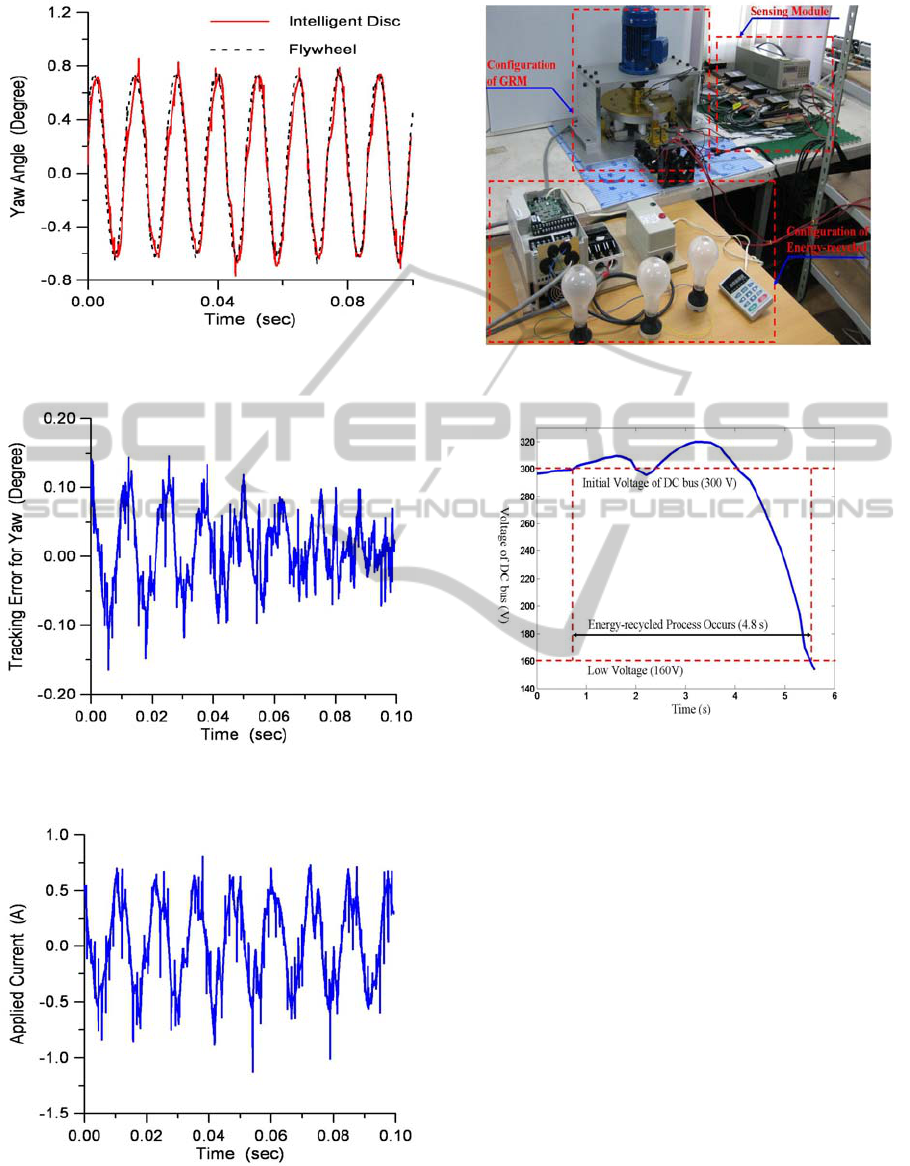
Figure 8: Time Response of Yaw of SGRM under FLSMC
Law by Experiment.
Figure 9: Tracking Error of Yaw of SGRM under FLSMC
Law by Experiment.
Figure 10: Applied Current for Yaw Tracking by
Experiment.
Figure 11: Experimental Setup for Flywheel Cell
Discharge.
Figure 12: Discharge Curve for Flywheel Cell by
Experiment.
ICINCO2012-9thInternationalConferenceonInformaticsinControl,AutomationandRobotics
376
