
A Service-based Integration for an improved Product Lifecycle
Management
Stefan Silcher
1
, Max Dinkelmann
2
, Jorge Minguez
1
and Bernhard Mitschang
1
1
Graduate School advanced Manufacturing Engineering (GSaME), University of Stuttgart, Stuttgart, Germany
2
Institute of Industrial Manufacturing and Management (IFF), University of Stuttgart, Stuttgart, Germany
Keywords:
Product Lifecycle Management, Service-oriented Architecture, Modular IT Integration.
Abstract:
The continuously changing environment is nowadays a major challenge for companies. The tough compe-
tition, growing customization of products and environmental regulations forces companies to continuously
adapt their business processes. In order to manage the complexity and reduce the effort for developing prod-
ucts and production, many IT systems are indispensable. Despite Product Lifecycle Management Technology
(PLM) the growing heterogeneous IT landscapes lack of a continuous support for business processes and get
quickly unmanageable. In this paper PLM technology is extended by a service-based integration approach.
Therefore, a modular service-based architecture was developed which will be presented in detail. The archi-
tecture describes how the whole product life cycle can be integrated more efficiently. The characteristics and
findings of our approach are presented as well as a first prototype covering the production planning.
1 INTRODUCTION
Manufacturing companies face several challenges
nowadays. Firstly, in some industry sectors there ex-
ists an overcapacity of produced goods, like in the au-
tomobile industry. There is a tough competition be-
tween companies for market share, price and qual-
ity of products. Secondly, the trend for customiza-
tion is growing. Companies deliver highly individu-
alized products to customers in order to increase their
competitiveness. This results in an increasing com-
plexity when developing the products and planning
their production. Thirdly, environmental regulations,
like reducing energy consumption and greenhouse gas
or replacement of harmful materials, force producing
companies to be highly innovative in developing new
technologies, materials and processes.
These challenges lead together with a highly vola-
tile market to new requirements for manufacturing
companies. To consolidate or increase the market
share, they have to enhance the adaptability of their
company in many ways. Their production has to be
as flexible as possible to produce highly customizable
products in the same production line. Changes of the
factory layout have to be performed in a very short
time and often with increasing frequency in order to
get shorter production times. Therefore, the exchange
of data between the digital and physical factory has to
be improved. This means, the actual state of the phys-
ical factory should be reflected in the model of the
digital factory at any time. This enables a faster reac-
tion on appearing problems or failures in the physical
factory. Additionally, the organization has to be adap-
tive as well. Hence, changes in the business processes
have to be smoothly performed (Jovane et al., 2009).
The first approaches to organize and provide the
product data over their whole life cycle came with the
Product Data Management (PDM). Introducing PDM
systems enormously reduces the effort to handle prod-
uct data, but the systems do not consider the processes
in the product life cycle. Therefore, the concept of
PDM was extended to monitor and manage these pro-
cesses and Product Lifecycle Management was intro-
duced (PLM). The goal is to optimize and standardize
the processes to execute them efficiently and there-
fore save time and money (Saaksvuori and Immonen,
2008), (Stark, 2004).
Additionally, the tasks within a process are sup-
ported by software applications. This leads to a faster
execution of single tasks and consequently reduces
the execution time of the process. However, several
problems arise when a high number of applications
are installed. One of these problems is the emergence
of information silos. The characteristic of such an
IT landscape is often distributed, heterogeneous and
proprietary. Coupling applications by implementing
38
Silcher S., Dinkelmann M., Minguez J. and Mitschang B..
A Service-based Integration for an improved Product Lifecycle Management.
DOI: 10.5220/0003996100380047
In Proceedings of the 14th International Conference on Enterprise Information Systems (ICEIS-2012), pages 38-47
ISBN: 978-989-8565-10-5
Copyright
c
2012 SCITEPRESS (Science and Technology Publications, Lda.)

point-to-point interfaces reduces the problem of in-
formation silos, but such solutions get quickly very
complex and hard to manage and maintain.
The motivation of our work is to build an archi-
tecture, which provides the needed flexibility in the
IT landscape of manufacturing companies. The pro-
cesses within PLM have to be continuously supported
by IT systems, these systems have to be loosely cou-
pled to provide the needed flexibility. Existing ap-
plications should be integrated into the new architec-
ture. Additionally, the management and maintainance
effort of the infrastructure has to be reduced and the
availability of data within the product life cycle im-
proved.
To realize such an architecture, a flexible solu-
tion is needed to flexibly integrate the applications of
the product life cycle. A commonly used paradigm
today is the Service-oriented Architecture (SOA).
SOA provides a flexible integration of applications
by loose coupling and reusing services, which are
self-contained, platform-independent and discover-
able (Erl, 2005). The use of standardized technology
like Web services to implement services allows easily
maintaining, extending or exchanging of an interface.
Moreover, Web services can be composed to work-
flows, which are modeled in standardized languages
like Business Process Execution Language (BPEL)
(OASIS, 2007) or Business Process Model and Nota-
tion (BPMN) (OMG, 2011). These workflows can be
executed by corresponding workflow engines to sup-
port the business processes.
The flexible composition of Web services within
workflows enables a flexible IT support of business
processes, which is necessary to quickly adapt the
business processes in a highly volatile environment.
The platform-independence of Web services allows
exchanging data and information between heteroge-
neous applications. Relying on standards and loosely-
coupled applications simplify maintaining, changing
and extending the IT infrastructure (Weerawarana
et al., 2005).
A common middleware solution to integrate Web
services is the Enterprise Service Bus (ESB) (Chap-
pell, 2004). The ESB handles the routing of messages
to enable a loose coupling of applications. Most ESB
solutions possess a BPEL engine, which is able to ex-
ecute BPEL workflows. Additionally, the ESB can
offer functionality such as message queuing capabili-
ties or monitoring services.
This paper presents a service-based integration ap-
proach for PLM. The developed architecture is based
on an ESB hierarchy to integrate the product life cycle
in a modular way. The results of the implemented pro-
totype for the digital factory demonstrate the benefits
of the service-based solution. The benefits include the
flexible composition of IT tasks, implemented as Web
services, in workflows. The workflows support the
planner of the factory by automating recurring tasks
and saves therefore time and money. Additionally,
the management and extensibility effort of the imple-
mented prototype is enormously enhanced compared
to the previous solution with customized scripts.
The remainder of the paper is structured as fol-
lows: In Section 2, the challenges in PLM and the
problems of inadequate integration of applications are
discussed. Furthermore, the service-based approach
for PLM integration is presented and the current so-
lutions in application integration are described. The
implemented prototype for the integration of produc-
tion planning tools is depicted in Section 3 and ben-
efits and problems as well as further extensions are
discussed. In Section 4, related work is presented be-
fore summary and outlook are given in Section 5.
2 SERVICE-ORIENTED PLM
ARCHITECTURE
An efficient and effective IT support of PLM pro-
cesses is one of the major challenges in today’s man-
ufacturing companies. Using IT systems, especially
in the product development and production planning
phase, can reduce the time-to-market of new products
tremendously. At the same time failures and ramp-up-
time of production are reduced as well as the quality
of products is improved. Today, the time between de-
ciding to develop a new product and its production
start can be further reduced by a seamless integration
of the various tools in the product life cycle. These IT
systems are often legacy applications or information
silos difficult to integrate. In order to enhance the ef-
ficiency of production, the challenge is to enable an
efficient exchange of information within the plethora
of heterogeneous and distributed IT systems used dur-
ing the product life cycle.
The adoption of the SOA paradigm eases the
needed information exchange between heterogeneous
applications by using standardized interfaces like
Web services and decoupling service functionality
from its implementation. Hence, a modular integra-
tion of the various product life cycle phases is pre-
sented in Subsection 2.2. Modularity reduces the im-
plementation and maintenance effort of the IT infras-
tructure. Data exchange between the Web service
as well as their compositions is accomplished by an
ESB. Workflows are capable of automatically execut-
ing recurring tasks within PLM and therefore save
valuable time, as well as reducing errors.
AService-basedIntegrationforanimprovedProductLifecycleManagement
39
Distribution
& Support
Concept
Design &
Development
Production-
planning
Production
Retire &
Dispose
Phase 1 Phase 2 Phase 3 Phase 4 Phase 5 Phase 6
CAD
Wiki
PDM Machine
Control
Unit
CRM …
Simulation PDA… …
Digital Factory
Tools
MESBlog
…
Figure 1: Phases and Tools of the Product Life Cycle.
In Subsection 2.1, the separation of the product
life cycle in six phases, which is used in this paper,
is presented. The service-based PLM architecture is
described in Subsection 2.2. The ideas of a service-
based PLM integration to production networks are ex-
tended in Subsection 2.3. Subsequently, the motiva-
tion for an improved data exchange between the dig-
ital and physical factory and the current state of the
production planning are introduced in Subsection 2.4
and 2.5.
The first implementations within the Learning
Factory’s digital learning shell of the Institute of In-
dustrial Manufacturing and Management (IFF) are
presented in Section 3. This prototype realizes a
seamless service-based integration of systems in the
production planning and eases the data management
thanks to automating the data exchange between the
applications by implementing the process in a BPEL
workflow.
2.1 Product Life Cycle
The product life cycle is heterogeneous in many ways.
Therefore, it is split in different phases, each of them
represent a characteristic activity. In Figure 1, the dif-
ferent phases of the product life cycle can be seen.
The separation of the product life cycle considers not
only the different activities in each phase, but also the
support with tools and the management of data.
In the first phase, the ’concept’ phase (C), ideas
for new products are generated and market analyses
are prepared. Therefore, wikis, blogs or social net-
works are used and often unstructured data has to be
handled and interpreted.
The ’design & development’ phase (DD) is de-
termined by developing and designing the various
parts of the products. Tools like Computer-aided De-
sign (CAD) and Product Data Management systems
(PDM) manage the high volume of data within this
phase.
In the next phase, the ’production planning’ (PP)
is carried out, where process and resource data are
added to the product data and linked among each
other. This data is linked into Digital Factory Tools,
which generate a plan for the factory. The planned
production processes are simulated with simulation
tools to verify the sequence. The data volume, which
has to be handled, increases enormously in this phase
compared to the design and development phase.
Having the product development and production
planning completed, the production can start in phase
four, the ’production’ phase (P). Here, Manufactur-
ing Execution Systems (MES) are responsible for ap-
plying the production orders in the production. The
control unit provides a real-time control of the man-
ufacturing facilities. Feedback of the manufacturing
facilities is gathered and stored by the production data
acquisition unit (PDA) for later analysis.
Selling the products, their maintenance and the
customers comprise are the main tasks of phase five,
the ’distribution & support’ phase (DS). Customer
Relationship Management Systems (CRM) are used
for the linking of sold products and customers for any
kind of complaints or warranty issues.
The ’retire & dispose’ phase (RD) deals with the
disposal of the product. Information about assembly
and material composition of the product can help re-
gain valuable material or simplify the separation of
material for recycling.
2.2 Service-oriented Integration
PLM extends the concept of PDM by adding man-
agement and control of business processes for the
whole life cycle. The problem today is that IT sys-
tems poorly support business processes. Especially
the flexible IT support of business processes is of
great importance (Papazoglou et al., 2007). There-
fore, a service-based architecture is needed, which al-
lows to implement a continuous IT support along the
whole product life cycle. Additionally, business pro-
cesses must be adapted in an easy manner as part of
the IT infrastructure.
Therefore, a modular service-based architecture
ICEIS2012-14thInternationalConferenceonEnterpriseInformationSystems
40
© GSaME, Universität Stuttgart
17
Ergänzungsprogramm Technik
Stefan Silcher
0
1
2
3
4
Product Lifecycle Management
App
PLM
1
App
PLM
2
WS
PLM
1
WS
PLM
2
BS
PLM
1
BS
PLM
2
PLM-Bus
Layered PLM Architecture
App
C
2
App
C
1
WS
C
2
WS
C
1
BS
C
2
BS
C
1
ESB
C
App
DD
2
App
DD
1
WS
DD
2
WS
DD
1
BS
DD
2
BS
DD
1
ESB
DD
App
PP
2
App
PP
1
WS
PP
2
WS
PP
1
BS
PP
2
BS
PP
1
ESB
PP
App
P
2
App
P
1
WS
P
2
WS
P
1
BS
P
2
BS
P
1
ESB
P
App
DS
2
App
DS
1
WS
DS
2
WS
DS
1
BS
DS
2
BS
DS
1
ESB
DS
App
RD
2
App
RD
1
WS
RD
2
WS
RD
1
BS
RD
2
BS
RD
1
ESB
RD
0
1
2
3
4
Phase 1
Phase 2
Phase 3
Phase 4
Phase 5
Phase 6
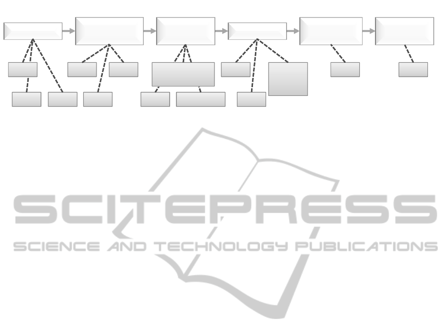
Figure 2: Service-based Integration Architecture for Product Lifecycle Management.
was developed with different integration layers, to ef-
ficiently integrate the plethora of applications, used in
the product life cycle, as well as to flexibly support
the business processes. The developed architecture,
which is presented in Figure 2, uses a pillar for every
phase of the product life cycle. Furthermore, the six
phases are integrated with an additional pillar for the
overall PLM (Silcher et al., 2011).
Each pillar is represented by a phase-specific ESB
that integrates all the applications of the correspond-
ing phase. These phase-specific characteristics can
be supported directly. A distinction is made between
phase-specific ESBs and the phase-overlapping PLM-
Bus. This solution with multiple ESBs builds a hier-
archy to efficiently manage all the processes in the
whole product life cycle.
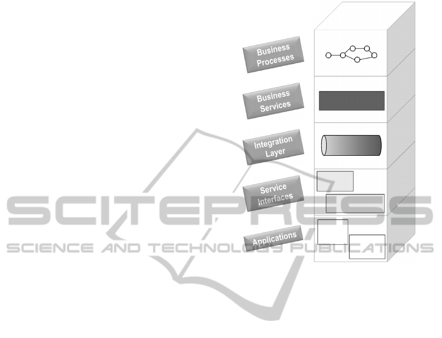
The vertical integration of each product life cy-
cle phase is clearly structured by distinguishing dif-
ferent levels of abstraction (Minguez et al., 2010).
Hence, the functionality and data, provided by each
application, is exposed as Web service in small, func-
tional units. These units can be composed to work-
flows, which support the execution of business pro-
cesses. The five layers are explained in Subsection
2.5 in more details.
The horizontal, phase-overlapping integration is
performed by the PLM-Bus, which connects the
phase-specific ESB’s as a central backbone. The sep-
aration of phase-specific integration and holistic PLM
integration contains several advantages (Silcher et al.,
2011). Particularly, the possibility of adapting the
ESB to the requirements of each phase like availabil-
ity, data throughput and time requirements are of great
importance.
The PLM-Bus is responsible to manage the phase-
overlapping data exchange, tasks and processes. The
PLM-Bus should provide information about available
Web services of all phases as well as authorization
and authentication as a single sign-on service. Pro-
cesses like change and failure management have to
be coordinated by the PLM-Bus. Additionally, En-
terprise Resource Planning systems and other appli-
cations, which cannot be assigned to a specific phase,
should be directly integrated by the PLM-Bus.
2.3 SOA for Production Networks
Previously not considered was the fact, that most
companies are not involved in the whole product life
cycle. Only the Original Equipment Manufacturers
(OEM’s) treat the product life cycle from the devel-
opment to the recycling of the product. Small and
Medium-sized Enterprises (SMEs), in particular sup-
pliers of OEMs, focus their work on one or two phases
of the presented product life cycle. Therefore, a
phase-specific integration is often sufficient to cover
their whole business area. This is not only profitable
for the SMEs, which benefit from the advantages of
a service-based IT infrastructure. Especially for the
OEM’s, the change of the SMEs IT landscape to an
SOA can be valuable.
A service-based communication improves the
quality of the data exchange, due to standardized Web
service interfaces, workflow definition or data ex-
change formats. Additional, asynchronous commu-
nication eases the loose coupling systems of the com-
AService-basedIntegrationforanimprovedProductLifecycleManagement
41
panies.
Therefore, the integration of SMEs in the business
process of an OEM is useful to have a defined way of
communication between the companies. E.g. changes
in the design of a product, made by an SME, can be
necessary due to inconsistencies in assembly tests of
the OEM. The OEM can describe the problems and
send them to the SME, where automatically an ex-
posed process is triggered to solve the resulting prob-
lem.
Therefore, the presented architecture can be easily
extended to manage data and processes in production
networks covering all involved companies, e.g., from
OEM to all suppliers. The challenge would be to con-
vince all suppliers and customers of a company to mi-
grate their IT infrastructure to SOA. Beside the tech-
nical challenge it poses an organizational challenge.
2.4 Digital and Physical Factory
Today, one key to a more efficient factory is the cou-
pling of the digital and physical factory. The vision
is to have available an up-to-date digital copy of the
physical factory at any time. Based on the current
state, different simulations could be executed to fore-
cast the short and medium term development of the
factory and its production.
The problem is to provide status information of
the production environment in real-time to the digi-
tal factory in order to automatically run a simulation
model out of that data (K
´
ad
´
ar et al., 2010). The pre-
sented architecture improves the availability of data
in the production environment by exposing Web ser-
vice interfaces and loosely coupling of applications in
the infrastructure, which allows a faster data exchange
between the digital and physical factory.
The IFF at the University of Stuttgart has built a
Learning Factory, which contains a digital learning
shell and a physical factory. The digital learning shell
contains many tools for planning and optimizing the
digital model of the factory. The central application
is a database to store product, process and resource
(PPR) data, also called PPR-Hub. Around this PPR-
Hub, there are several tools for the factory optimiza-
tion. Amongst others, there is a layout planning table,
where a group of people can cooperatively optimize
the factory layout (Kapp et al., 2005). The most im-
portant tool in a digital factory is a simulation applica-
tion. Additionally, a logistic simulation tool is used to
verify the planned production processes and various
simulated scenarios (Kapp et al., 2003).
The presented tools and others can exchange data
with the PPR-Hub by executing (Visual Basic) scripts.
These scripts are customized point-to-point connec-
0
1
2
3
4
Digital
Factory
Tools
Layout Planning
Table Service
PPR-Hub
Service
ESB
PP
Layout Planning
Service
Layout
Planning
Table
Production
Planning
Figure 3: Integration Pillar for the Production Planning
Phase.
tions. Therefore, the inclusion of new tools or sub-
stitution of an existent tool is associated with a great
effort. Substituting a tool leads to a complete reim-
plementation of the script.
The physical factory of the IFF, called iTRAME,
consists of modular manufacturing units, which are
connected with a universal plug-and-play mechanism
and can be easily exchanged (Dinkelmann et al.,
2011).
Currently, the factory layout of the physical fac-
tory can be automatically detected and copied with a
script to the digital planning environment. Due to the
high effort for implementing these scripts, no further
information is used in the planning environment, e.g.
process data and time information of the production.
This information would help to understand the cur-
rent situation in the production, when planning and
real data are compared, and thus would enhance the
planning accuracy, but also increases the planning ef-
fort.
The goal of implementing an SOA is to replace the
tight coupling of the applications with scripts by Web
service interfaces, which can be flexibly composed
into workflows. The workflows can support the plan-
ner by automatically or semi-automatically executing
recurring tasks in the product life cycle, e.g. when
new products are introduced, changes in the product
mix are detected, or machine failures appear.
ICEIS2012-14thInternationalConferenceonEnterpriseInformationSystems
42
PPSB
Access-DB
Planning
Table
PPR-
Hub
Workflow
Engine
MSMQMSMQ
Content-
based
Router
MSMQ
Workflow Management Portal Layout Planning Table
Figure 4: Architecture of Integrated IT systems.
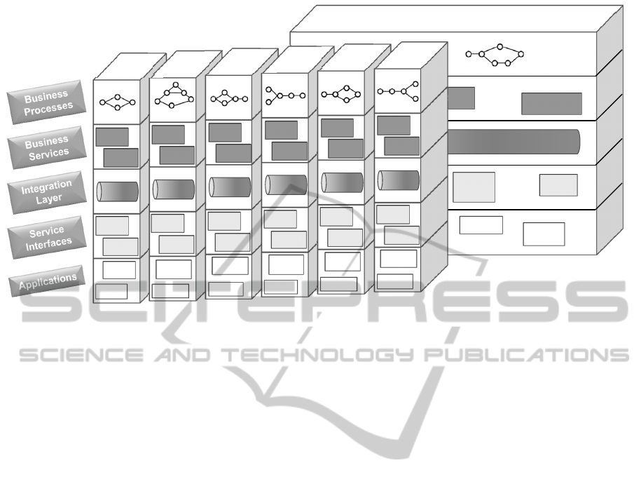
2.5 Production Planning
Implementing the presented service-based architec-
ture for PLM in the production planning is figured out
in Figure 3.
Layer 0 contains the various applications of the
production planning, e.g. digital factory tools, layout
planning table, simulation tools. The data and func-
tionality of the applications is exposed to other tools
by means of Web service interfaces, which are placed
in Layer 1. The ESB in the integration layer (Layer 2)
routes the messages sent and received by the Web ser-
vice interfaces to the desired destination. Addition-
ally, it performs the data transformations from propri-
etary data formats to a canonical data format of the
ESB, which is described in Subsection 3.3. The busi-
ness services in Layer 3 compose the Web services to
small processes, which manage the data exchange be-
tween two applications. The business process layer at
the top of the pillar (Layer 4) represents the IT imple-
mentation of the business processes.
Web service technologies are platform indepen-
dent, which is a great advantage when integrating pro-
prietary heterogeneous systems like the current IT in-
frastructure at the IFF. In the implemented prototype,
the messages are exchanged over Message Queues
(MQ), which allow a reliable, asynchronous commu-
nication between the participating applications and
improve the loose coupling of applications (Hohpe
and Woolf, 2003). More details on our prototype im-
plementation will be given in the subsequent chapter.
3 IMPLEMENTATION OF
SERVICE-BASED
INTEGRATION FOR
PRODUCTION PLANNING
To show the benefits of the service-based approach,
some applications of the Learning Factory’s digital
learning shell were integrated by the presented ap-
proach and architecture. Therefore, the databases of
each application were equipped with Web service in-
terfaces and a web-based portal was developed to con-
trol and manage workflows executed in the production
planning environment.
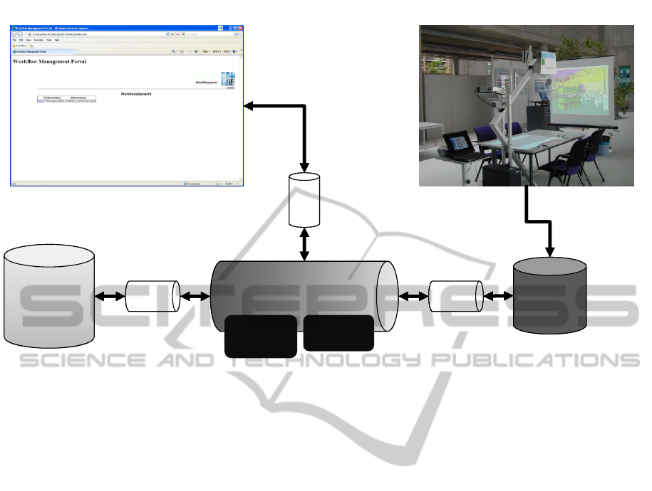
3.1 Prototype of Service-based
Production Planning
In the first phase of the implementation, the central
data hub, which stores the PPR data, should be inte-
grated with a layout planning tool (Kapp et al., 2005).
The developed architecture is shown in Figure 4.
The core of this architecture is the Production
Planning Service Bus (PPSB), which is based on the
OpenESB, an open source implementation of an ESB
(OpenESB, 2010). BPEL workflows can be executed
AService-basedIntegrationforanimprovedProductLifecycleManagement
43
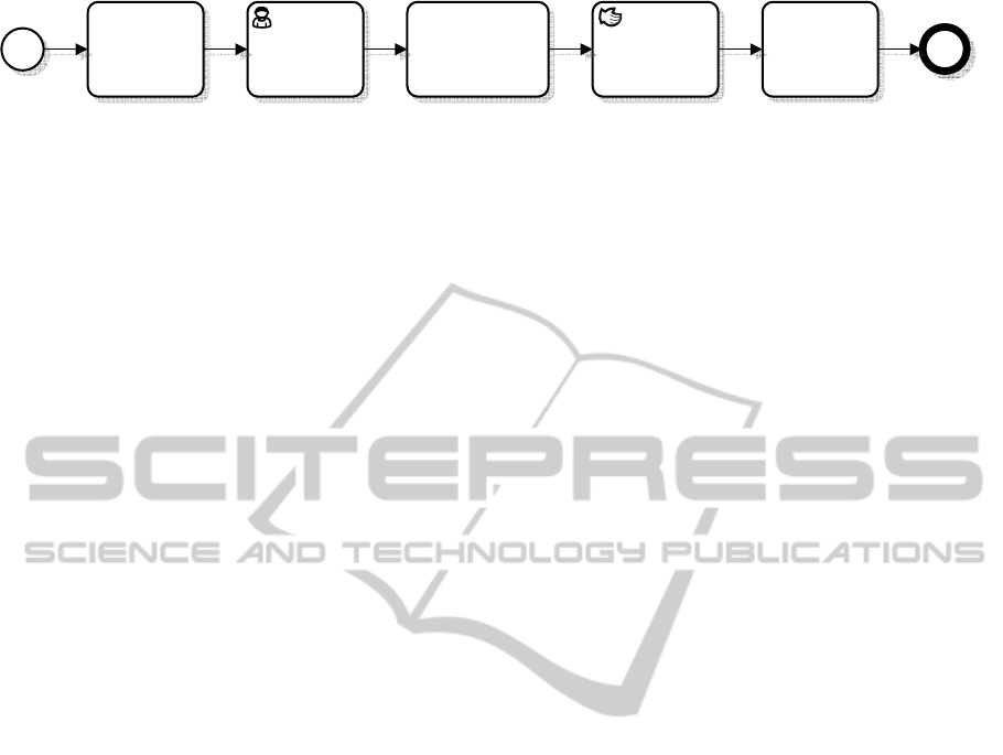
Load
Projects
Select
Project
Load Resource
Data to
Planning Table
Perform
Layout
Planning
Store
Resource
Data in
PPR-Hub
Load Projects Select Project
Load Resource Data
to Planning Table
Perform Layout
Planning
Store Resource
Data in PPR-Hub
Figure 5: BPMN Workflow for Layout Planning.
in the workflow engine of the OpenESB. To adminis-
trate the workflows, the Workflow Management Por-
tal was developed, where the production planner can
start, control and if necessary restart or stop the avail-
able workflows. The usage of the implemented plan-
ning workflow is described in Section 3.2.
Using asynchronous communication improves the
loose coupling between the applications. They don’t
communicate directly with each other; instead the
messages are sent over MQs. A MQ enables a reliable
communication between the participants by receiving
messages and storing them persistently until the MQ
has successfully delivered the message to the receiver.
This means, the receiver can be temporarily unavail-
able without disrupting the whole system or blocking
the sender of a message. Therefore, the usage of MQs
makes the system more robust against network or ap-
plication failures and improves the loose coupling of
the applications.
In the presented prototype, Microsoft Message
Queuing (MSMQ) is used to connect the systems with
the OpenESB. To enable the OpenESB to communi-
cate with the MSMQs, a MSMQ Binding Component
is provided by the developers of the OpenESB.
To integrate the applications within the architec-
ture, Web service interfaces were developed to en-
able the exchange of messages with other applica-
tions. For the Workflow Management Portal, PPR-
Hub and Layout Planning Table a Web service inter-
face was implemented for each. Due to the fact, that
no source code was available for the Layout Planning
Table, the only way to exchange data with this tool
was an interface to its access database.
All the messages exchanged in the system rely on
the same canonical data format. Thus, all the mes-
sages have the same structure and don’t have to be
transformed between the different systems. The only
effort is to generate a correct message, including the
data provided by the database. To reduce the effort, a
common library that automatically generates the mes-
sages in the correct format is implemented to be used
by all Web services.
The loose coupling of the integrated applications
is ensured by using a content-based router (Hohpe and
Woolf, 2003). This means, an application must not
know the network address or endpoint of the desti-
nation system of a message. The message can just be
sent to the ESB, where the content-based router deter-
mines the destination by inspecting the content of the
message. Therefore, the endpoint can be looked up
in a database, when the destination system is known.
This allows transferring applications to other servers
or changing their endpoints without affecting other
applications. The only thing to do is to change the
corresponding endpoint in the database of the content-
based router and all other applications can communi-
cate again with the changed application. The purpose
of the content-based router is to decouple applications
and to enhance adaptability.
3.2 Layout Planning Workflow
The workflow implemented for the prototype controls
the data flow between the systems presented in the
previous subsection. A BPMN model of this work-
flow is presented in Figure 5.
The first task ”Load Projects” of the workflow
sends all projects, which are stored in the PPR-Hub,
in a message to the Workflow Management Portal.
The message is extracted and the projects are pre-
sented in the portal.
The user is asked in the second task ”Select
Project”, to select the project he wants to modify in
the Layout Planning Table. The human icon in the
top left corner of the task indicates that a human in-
teraction is necessary in this task.
After selecting a project, the third task ”Load Re-
source Data to Planning Table” is started, which sends
a message containing the selected project to the PPR-
Hub. The resource information of this project is there-
upon sent over the ESB to the Layout Planning Table
and stored in its database.
In the fourth task ”Perform Layout Planning”, the
user can perform the layout planning to optimize the
material flow, the logistic processes, and so forth. The
hand icon in the top left corner of the task indicates
that this task has to be performed manually by the
user.
When the user finished the layout planning, the
last task ”Store Resource Data in PPR-Hub” is exe-
cuted. This task generates a message to send the op-
timized planning data over the ESB back to the PPR-
Hub, where they are stored and are now available for
other systems in the production planning.
ICEIS2012-14thInternationalConferenceonEnterpriseInformationSystems
44

3.3 Message Format
To efficiently exchange messages between the differ-
ent applications, an application-independent canoni-
cal data format was defined. Using a canonical data
format is best practice in integration, because it re-
duces the complexity of data formats when integrat-
ing new applications into the infrastructure (Chappell,
2004). Thus, the data of each application has to be
transformed to and from the canonical format, instead
of one transformation from each to every application.
This reduces the complexity of integration and im-
proves the extensibility and scalability of the integra-
tion approach.
The defined message format consists of two parts
and is based on XML. The first part contains infor-
mation about the message type and the routing. The
content-based router derives the destination of the
message from the message type and writes them in
the routing information part of the message.
The second part of the message contains the data
of a project. Currently, this part entails information
about the production resources, but can be easily ex-
tended with product, process and order information in
the future, when more applications are integrated into
the architecture.
<?xml version="1.0" encoding="utf-8"?>
<ProjectMessage xmlns:xsi="...>
<CommonInfos xmlns="http://tempuri.org/ESB">
<RoutingInfos>
<OriginSystem>PPR-Hub</OriginSystem>
<DestinationSystem>
<SystemID>WP</SystemID>
<SystemURI>http://localhost:9007/
PortalService/</SystemURI>
</DestinationSystem>
</RoutingInfos>
<MessageType>0</MessageType>
. . .
</CommonInfos>
<Projects xmlns="http://tempuri.org/ESB">
<Resources>
<ModuleTypes>
<ModuleID>1</ModuleID>
<Modulename>modulename</Modulename>
<Type>1</Type>
<FileName>test.cad</FileName>
<BitmapName>test.bmp</BitmapName>
<Module>
<ObjectID>1</ObjectID>
<Objectname>objectname</Objectname>
<Position>
<Position_X>300</Position_X>
<Position_Y>80</Position_Y>
<Position_Z>0</Position_Z>
<Rotation_X>0</Rotation_X>
<Rotation_Y>0</Rotation_Y>
<Rotation_Z>0</Rotation_Z>
</Position>
</Module>
<Module>
. . .
</Module>
</ModuleTypes>
</Resources>
<ProjectID>1</ProjectID>
<Projectname>test project</Projectname>
</Projects>
</ProjectMessage>
The messages are generated by the Web services,
which read the data from the database of the source
system and fill them into the XML schema. After
completing the message, it is sent to the router of the
PPSB, where the destination is derived from the mes-
sage content and forwarded to the destination Web
service interface. After receiving the message, the
information is extracted from the XML message and
stored in the database of the destination system.
3.4 Review and Extension of the
Prototype
For the manageability of our IT infrastructure ap-
proach, this prototype demonstrates great advantages
compared to the previously implemented point-to-
point interfaces between the applications:
• The ESB as central integration backbone eases the
connection of the heterogeneous applications to
this prototype.
• The use of a canonical data format reduces the
number of different transformations, which leads
to a better extensibility and scalability of the in-
frastructure.
• The content-based router enables the loose cou-
pling of the applications to the ESB by introduc-
ing a central database for the registration of appli-
cation endpoints.
• The implementation of MQs boosts the loose cou-
pling at the connectivity layer. Additionally, the
robustness of the complete infrastructure is im-
proved due to temporarily failures of networks or
applications.
• Changing from a synchronous to an asynchronous
communication increases the performance by
reducing unnecessary blocking of applications
when waiting till a message is send or is available
to receive.
The presented prototype allows the production
planner to manage the data of the integrated appli-
cations at a single point, the Workflow Management
AService-basedIntegrationforanimprovedProductLifecycleManagement
45

Portal. In the portal, the planner can see the available
workflows and start, stop or restart them.
Proprietary applications can be integrated in var-
ious ways into an SOA. To access the functionality
of a program, an available interface can be used or a
new one can be implemented, provided that the source
code is available. If neither is available, the func-
tionality of a program cannot be easily integrated in
a workflow, as in our case. Nevertheless, the data can
be accessed by an interface over the program logic or
directly over the database of a program. In the pro-
totype the databases of the integrated programs were
equipped with an Web service interface which lead to
an enhances data exchange between the applications.
To fully automate the planning processes, functional-
ity has to be exposed as Web services to be able to
execute them within a workflow activity.
Extending the prototype with a simulation tool
like the logistic simulation tool would make sense.
The optimized layout could be verified by simulating
the production processes and the throughput can be
measured. Therefore, the simulation tool has to be
equipped with a Web service interface to receive the
necessary data for the simulation.
The canonical message format has to be extended
to include beside the resource data also product and
process data. In the currently used data format, this
extension is already provided and can be easily per-
formed. Additionally, the Web service interface of
the PPR-Hub has to be extended to read and write
the product and process data. On the other hand, the
Web service interface of the Layout Planning Table
remains unchanged. Now, there are two alternatives
to integrate the simulation tool in a workflow. The
presented layout planning workflow can be extended
to include the simulation tool or a new simulation
workflow can be implemented to control the data ex-
change between the PPR-Hub and the simulation tool.
In the second case, the layout planning workflow and
the new simulation workflow have to be executed con-
secutively.
4 RELATED WORK
In the last few years, the main PLM vendors like Das-
sault Syst
`
emes, PTC and Siemens PLM Software ex-
tended their PLM solutions with a service-based ap-
proach to get the desired continuous integration of
the product life cycle (CIMdata, 2006). However,
they adopt their proprietary integration middleware
and thus resulted in restricted interoperability prop-
erties: lacking to integrate systems of other vendors,
missing flexibility in business process support, and
applications are not loosely coupled to the integration
middleware. Furthermore, the interfaces are not open,
so it is hard or impossible for other software vendors
to connect their applications to these middleware sys-
tems.
Rantzau et al. implemented a Data Change Prop-
agation System called CHAMPAGNE for heteroge-
neous information systems (Rantzau et al., 2002).
The CHAMPAGNE platform manages dependencies
between the schemas of different distributed applica-
tions. Compared to the presented prototype in this pa-
per, CHAMPAGNE implements a tight coupling to the
participating applications. Hence, changes in a sys-
tem can only be made when the propagation scripts
are changed accordingly, which my become quite
some hassle.
5 CONCLUSIONS AND
OUTLOOK
Highly volatile markets and growing competition
force companies to continuously increase their effec-
tiveness. Their flexibility has to be improved to adapt
to the constantly changing environment. This can be
achieved by a more flexible support of business pro-
cesses and the IT infrastructure. Additionally, the
applications, which support a business process task,
have to be better integrated to improve the data and
information flow. The vision is a continuous integra-
tion of all applications used in the product life cycle
to accelerate the data exchange.
The paper presents a service-based architecture to
integrate the different phases of the product life cy-
cle. The phase-overlapping integration is performed
by the PLM-Bus, which allows exchanging data and
coordinating processes between the phases. The ben-
efits of this architecture are a clear separation between
different levels of abstraction as well as the possibility
to adapt each ESB to the requirements of each phase
like availability, data throughput and time require-
ments. Possible extensions to integrate customers and
suppliers in this infrastructure to get a consistent in-
formation exchange in the production network were
discussed.
Furthermore, the developed prototype based on
the Production Planning Service Bus performs a
service-based integration of the production planning
environment at the IFF. The benefits and problems of
the prototype and the integration of proprietary appli-
cations are discussed and an outlook on useful exten-
sions of the implementation in the production plan-
ning is given.
The next step in the service-based integration of
ICEIS2012-14thInternationalConferenceonEnterpriseInformationSystems
46

PLM is the implementation of the PLM-Bus to effi-
ciently couple the production planning and produc-
tion phase. The goal is to establish a bidirectional
communication between the digital and physical fac-
tory to automatically adopt the current production sta-
tus for the planning and to accomplish an optimized
planning in the production environment.
ACKNOWLEDGEMENTS
The authors extend their sincere thanks to Fabian
Laux, who contributed in developing and implement-
ing the prototype of the service-based production
planning integration.
Furthermore, the authors would like to thank the
German Research Foundation (DFG) for financial
support of this project as part of the Graduate School
of Excellence advanced Manufacturing Engineering
(GSaME) at the University of Stuttgart.
REFERENCES
Chappell, D. A. (2004). Enterprise Service Bus: Theory in
Practice. O’Reilly Media, 1st edition.
CIMdata (2006). Service-oriented architecture for plm - an
overview of ugs soa approach. Technical report, CIM-
data, Inc.
Dinkelmann, M., Riffelmacher, P., and Westkmper, E.
(2011). Training concept and structure of the learn-
ing factory advanced industrial engineering. In
ElMaraghy, H. A., editor, Enabling Manufactur-
ing Competitiveness and Economic Sustainability,
Proceedings of the 4th International Conference
on Changeable, Agile, Reconfigurable and Virtual
Production (CARV2011), pages 624–629. Springer
Berlin Heidelberg.
Erl, T. (2005). Service-Oriented Architecture: Concepts,
Technology, and Design. Prentice Hall International,
illustrated edition edition.
Hohpe, G. and Woolf, B. (2003). Enterprise Integration
Patterns: Designing, Building, and Deploying Mes-
saging Solutions. Addison-Wesley Longman, Ams-
terdam.
Jovane, F., Westk
¨
amper, E., and Williams, D. (2009). The
ManuFuture Road: Towards Competitive and Sus-
tainable High-adding-value Manufacturing. Springer,
Berlin, 1st edition.
K
´
ad
´
ar, B., Lengyel, A., Monostori, L., Suginishi, Y., Pfeif-
fer, A., and Nonaka, Y. (2010). Enhanced control of
complex production structures by tight coupling of the
digital and the physical worlds. CIRP Annals - Manu-
facturing Technology, vol. 59(1):437–440.
Kapp, R., Le Blond, J., and Westk
¨
amper, E. (2005). Fab-
rikstruktur und logistik integriert planen: Erweiterung
eines kommerziellen werkzeugs der digitalen fabrik fr
den mittelstand. wt Werkstattstechnik online, vol. 95
(2005), No. 4:191–196 (german).
Kapp, R., L
¨
offler, B., Wiendahl, H.-H., and Westk
¨
amper, E.
(2003). Der logistik-pr
¨
ufstand: Skalierbare logistik-
simulation von der lieferkette bis zum arbeitsgang. wt
Werkstattstechnik online, vol. 93 (2003), No. 1/2:31–
38 (german).
Minguez, J., Ruthardt, F., Riffelmacher, P., Scheibler, T.,
and Mitschang, B. (2010). Service-based integration
in event-driven manufacturing environments. In WISE
2010 Workshops, volume 6724 of Lecture Notes in
Computer Science, pages 295–308. Springer.
OASIS (2007). Web services business process execution
language version 2.0.
OMG (2011). Business process model and notation
(BPMN) version 2.0.
OpenESB (2010). http://www.logicoy.com/esb.php (last
visited: November 2011).
Papazoglou, M., Traverso, P., Dustdar, S., and Leymann, F.
(2007). Service-oriented computing: State of the art
and research challenges. Computer, vol. 40(11):38–
45.
Rantzau, R., Constantinescu, C., Heinkel, U., and Mei-
necke, H. (2002). Champagne: data change prop-
agation for heterogeneous information systems. In
Proceedings of the 28th international conference on
Very Large Data Bases, VLDB ’02, pages 1099–1102.
VLDB Endowment.
Saaksvuori, A. and Immonen, A. (2008). Product Lifecycle
Management. Springer, Berlin, 3rd edition.
Silcher, S., Minguez, J., and Mitschang, B. (2011). Adopt-
ing the manufacturing service bus in a service-based
product lifecycle management architecture. In Pro-
ceedings of the 44th International CIRP Conference
on Manufacturing Systems: ICMS ’11; Madison, Wis-
consin, USA, pages 1–6. Online.
Stark, J. (2004). Product Lifecycle Management: 21st Cen-
tury Paradigm for Product Realisation (Decision En-
gineering). Springer, Berlin, 1st edition.
Weerawarana, S., Curbera, F., Leymann, F., Ferguson, D. F.,
and Storey, T. (2005). Web Services Platform Ar-
chitecture: Soap, WSDL, WS-Policy, WS-Addressing,
WS-Bpel, WS-Reliable Messaging and More. Prentice
Hall International, USA.
AService-basedIntegrationforanimprovedProductLifecycleManagement
47
