Solving the Indoor SLAM Problem for a Low-Cost Robot using
Sensor Data Fusion and Autonomous Feature-based Exploration
Luciano Buonocore
1
, Cairo Lúcio Nascimento Júnior
2
and Areolino de Almeida Neto
1
1
Universidade Federal do Maranhão, Av. dos Portugueses S/N, São Luis, Maranhão, Brazil
2
Instituto Tecnológico de Aeronáutica, São José dos Campos, Brazil
Keywords: Sensor Data Fusion, Feature-based Autonomous Exploration, Visual Sensor, Low-Cost Robot, SLAM.
Abstract: This article is concerned with the solution of the SLAM (Simultaneous Localization And Mapping) problem
in an indoor environment using a low-cost mobile robot that autonomously explores the environment. The
robot was constructed with a distance measurement subsystem composed of three types of sensors: a
wireless webcam with a laser pointer (a visual sensor), two infrared sensors and an ultrasonic TOF (time-of-
flight) sensor. Firstly, an algorithm that requires a small computational load is used to fuse the noisy raw
data acquired by these sensors and generate the environment features. These features are then used by a
particle filter to solve the SLAM problem. An autonomous feature-based exploration algorithm was
implemented and is also presented. The results obtained in the experiments carried out in two small indoor
environments show that the estimated environment map generated when the robot uses the autonomous
exploration algorithm is very similar to the one generated when the robot poses were manually chosen.
1 INTRODUCTION
Nowadays it is highly desirable that a mobile robot
is able to navigate in an unknown environment
autonomously, which means that the robot needs to
construct a map of the environment and at the same
time locate itself within this map, a problem
commonly referred as SLAM (Simultaneous
Localization And Mapping) in the robotics literature.
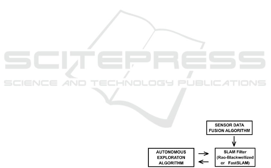
Three software modules, which run in a
cooperative form, were used (Figure 1): a) a sensor
data fusion algorithm; b) an autonomous feature-
based exploration algorithm; and c) a version of
particle filter (Rao-Blackwellized). The two first
modules were developed by the authors and are the
main contributions of this article.
The robot, which was designed and built by the
authors of this article, named SLAMVITA (final
cost around US $ 2,100.00) employs three types of
sensors: a wireless webcam with a laser pointer (a
visual sensor), two infrared sensors and an ultrasonic
TOF (time-of-flight) sensor or sonar. An algorithm
was developed to transform the noisy data acquired
by these sensors into features that geometrically
represent the environment (walls).
A particle filter algorithm, known as Rao-
Figure 1: Algorithm modules to solve the indoor SLAM
problem.
Blackwellized or FastSLAM (Huge and Bailey,
2006), was implemented based on a proposal by
(Thrun et al., 2005) which was modified to use the
odometry motion model, such that the outputs of the
encoders were computed as control information.
This algorithm simultaneously estimate the robot
poses and the environment map in solution of
SLAM problem.
The autonomous exploration algorithm is
structured as rules to perform two basic tasks: a) to
decide the best target to explore in the environment
in an incremental way; and b) to decide when to
finish the exploration task.
This article is organized as follows. Section 2
introduces the SLAM problem and the approaches
used to solve it. In Section 3 the proposed sensor
data fusion algorithm is presented and shows the
407
Buonocore L., Lúcio Nascimento Júnior C. and de Almeida Neto A..
Solving the Indoor SLAM Problem for a Low-Cost Robot using Sensor Data Fusion and Autonomous Feature-based Exploration.
DOI: 10.5220/0004000504070414
In Proceedings of the 9th International Conference on Informatics in Control, Automation and Robotics (ICINCO-2012), pages 407-414
ISBN: 978-989-8565-22-8
Copyright
c
2012 SCITEPRESS (Science and Technology Publications, Lda.)
results of a simple experiment which was designed
to measure its accuracy for environment mapping.
Section 4 explains the autonomous exploration
algorithm. Section 5 presents the experiment results
obtained by the solution for the SLAM problem with
and without using the proposed autonomous
exploration algorithm in a small indoor environment.
The same Section shows that the proposed solution
fails if the raw data of any two SLAMVITA robot
sensors are used by the fusion algorithm.
2 SLAM PROBLEM OVERVIEW
Some approaches employed to solve the SLAM
problem were obtained using different techniques,
such as fuzzy logic (Huge, 2001; Aguirre and
Ganzález, 2002), artificial neural networks (Thrun,
1993), and the Dempster-Shafer theory
(Milisavljević, Bloch and Acheroy, 2008). However,
most of the literature employs the so-called
probabilistic SLAM solutions (Thrun, Burgard and
Fox, 2005), using different combinations of sensors,
such as laser scanner and CCD camera (Castellanos,
et al., 1998) or two sonars and six infrared sensors
(Vazquez and Malcolm, 2005). Many other sensor
combinations may be found in the literature.
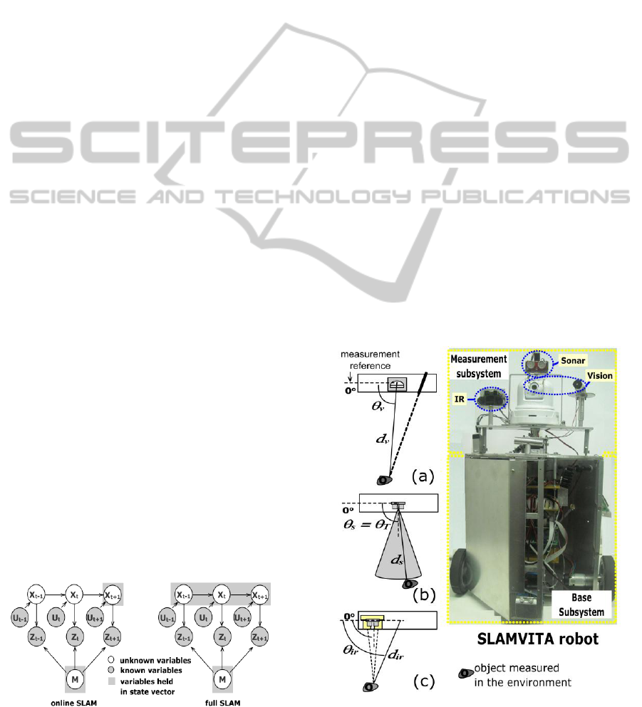
Figure 2 shows a graphic representation of the
two main forms of probabilistic SLAM problems
(Thrun et al., 2005): online SLAM and full SLAM.
In the solution of the SLAM problem the robot poses
and environment map are unknown estimated
variables (X and m, respectively) that must be
computed at every time step t, and the accuracy of
one variable is important to best estimate the other.
This fact is referred in the literature as the “chicken
and egg” problem.
This article uses a version of a particle filter
known as Rao-Blackwellized or FastSLAM, where
samples (particles) are employed to hold hypothesis
of the robot poses along the EKF (Extended Kalman
Filter) to estimate each feature extracted by the
proposed sensor data fusion algorithm. Moreover,
the choice for FastSLAM version 1.0, instead of
version 2.0, is due to the high quality odometry
Figure 2: Forms of SLAM problems.
(Thrun et al., 2005) shown by the SLAMVITA robot
in the experiments.
3 PROPOSED SENSOR DATA
FUSION ALGORITHM
A single sensor hardly ever can provide enough
information about the environment because of its
limited field-of-view. The solution to overcome such
shortcomings requires the use of two or more
sensors whose information must be fused. Three-
level architecture for robot sensor data fusion is
presented by (Visser, 1999) in which three methods
of data fusion may be applied: a) cooperative; b)
competitive; and c) complementary.
The proposed sensor data fusion algorithm only
uses competitive and complementary methods. In a
competitive fusion each sensor produces its own
estimated parameters, which are combined to
generate a single set of parameters (in this case, the
distance and the angle of the measured object). An
example of competitive fusion occurs when the
visual and infrared sensors measure the same object
in the environment. Complementary fusion is
applied when each sensor has only partial
information about the environment. It aims to
overcome the incompleteness of sensors being a
classical example the array of several sonars
attached around a mobile robot.
Figure 3: Measurement parameters (d, Ɵ) provided by the
SLAMVITA sensors: (a) visual, (b) sonar and (c) infrared.
ICINCO 2012 - 9th International Conference on Informatics in Control, Automation and Robotics
408
The SLAMVITA sensors are assembled on a
panning turret located at top of the robot (Figure 3).
The turret and the robot vertical axis are aligned and
the turret can be turned around its axis to execute an
180° scan procedure.
The parameters supplied by the sensors are the
distance (d) and angle (Ɵ) of the object measured
(details in Figure 3). These sensors were chosen in
function of the complementary information provided
by them. Due to their operating principles, the visual
and infrared sensors provide reliable directional
information (angle of the object), while the sonar is
mainly a distance sensor, because of its accuracy in
distance measurement (Ivanjko et al., 2009; Vazques
and Malcolm, 2005).
The visual sensor employed in SLAMVITA
robot uses active triangulation with calibration
targets proposed by (Nguyen and Blackburn, 1995)
and has never been used in the robotic literature for
mapping purpose. The operating principle (laser
center on image calculated in subpixel resolutions)
and experimental results performed in distance
measurements by the visual sensor are presented in
(Buonocore et al., 2010).
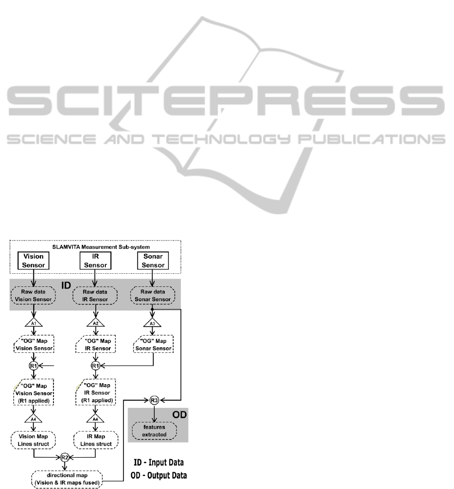
The proposed sensor data fusion algorithm is
informally described next to facilitate its
comprehension, which flowchart is shown in Figure
4. It is based on the following considerations:
It is assumed that the robot environment is
composed of walls (they are always orthogonal
Figure 4: Flowchart of the proposed sensor data fusion
algorithm.
to the floor but not necessarily to each other),
and these walls can have openings (such as
doors). Most structured indoor environments are
composed by walls, doors, etc. that may be used
as line segments into a compact map
representation (Yap and Shelton, 2009).
The occupancy grid (OG) and feature-based
mapping techniques are employed to represent
the environment in two dimensions.
The RANSAC algorithm (Zuliani, 2009) is used
to extract straight line segments from the
directional (visual and IR) maps.
The sonar measurements available in OG map
(OGs) and in its vector raw data are used to
eliminate noises in the directional OG maps and
to adjust the feature distances in the directional
fused feature-base map, respectively.
The distance parameters in the visual and IR
sensors are considered to have the same weights
to compute the straight line segments to be fused.
The input data (ID) shown in Figure 4 are the
distance/angle contained in each sensor raw data
acquired in an 180
o
scan, at each robot pose, with
1.8
o
angular resolution. The algorithm generates the
features extracted (output data, OD) as parameter-
zed lines. The proposed fusion algorithm is com-
posed by 4 specific algorithms and 3 fusion rules.
These rules (R1, R2 and R3) implement the data
fusion method while the specific algorithms (A1 to
A4) prepare the data to feed the rules. The pseudo-
codes for these procedures are available at ftp:
//labattmot.ele.ita.br/ele/luciano/My_Publications.
The basic concept in R1 rule is as follows: no
object detected by the sonar cone must be perceived
by the other two directional sensors. The application
of R1 rule justifies the use of the OG representation,
where the inverse sonar model is employed (Thrun
et al., 2005). Due to the surface reflection that is not
normal to the sonar acoustic wave, the sonar raw
data must be pre-processed before being employed
to remove these wrong data, keeping only those ones
that mainly reveal the true RCD (Region of Constant
Depth), reporting for walls in the environment
(Pandey et al., 2007).
To extract line segments from directional maps,
the proposed algorithm converts the OGv and OGir
internal representation (after applying R1 rule) to x-y
coordinates, which are held in separated vectors.
Then, the RANSAC method is used in A4 algorithm
to extract straight line segments (features) from
those vectors, one map at a time. For each
directional map, the A4 algorithm performs an
interpretation on the data vector to break it in
Solving the Indoor SLAM Problem for a Low-Cost Robot using Sensor Data Fusion and Autonomous Feature-based
Exploration
409
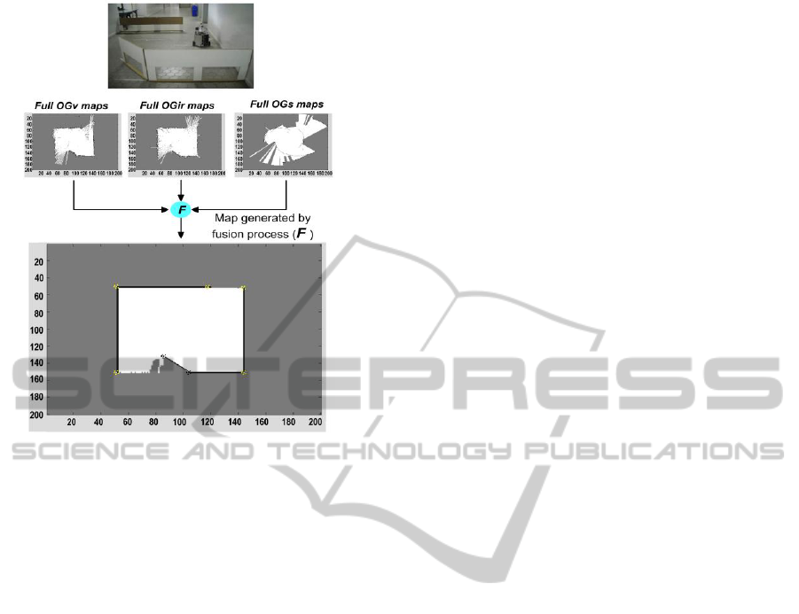
Figure 5: Comparison between OG maps computed from
each sensor raw data and one generated by the proposed
fusion algorithm.
segments that have significant variance in its data
that point to different straight line slope or also gaps
that may appear between line segments
(environment openings). All vector segments are
submitted to RANSAC trying to extract straight
lines that represent the section features of the
processing directional map.
The line segments extracted for each map are
combined in R2 rule, applying competitive or
complementary method. The competitive fusion is
selected if both sensors have data at specific angular
area. Otherwise, the complementary fusion takes
place, such as the case in which the visual sensor is
unable to define the laser spot at the camera image.
The R3 rule adjusts, if possible, the feature
distances of the fused directional map (after
applying R2 rule), searching for RCD in the angular
area that contains the normal straight line of each
feature in the map. Whenever the RCD is found, the
feature distance is adjusted using the sonar
measurement (RCD distance).
Figure 5 shows the geometrical representation of
the actual environment (photo), which in comparison
with each OG sensor map is more consistent and
noise free. The error obtained in this mapping
experiment was less than 1.5%. It is important to
notice that the map constructed in this experiment is
represented as full OG maps, instead of feature-base
ones. However, in SLAM applications, the features
for each robot pose must be processed and the
environment representation outputted by the
algorithm changed to feature-based map because of
its computational cost in the particle filter.
4 AUTONOMOUS
EXPLORATION ALGORITHM
The robot ability to explore an environment without
human intervention ensures its real autonomy. The
proposed sensor data fusion algorithm is nicely
complemented by an autonomous exploration
algorithm that uses the same environment map
representation. The autonomous exploration
algorithm developed in this article, from now on
denoted by AEA, is based on concepts presented by
(Newman, Bosse and Leonard, 2003) where
hallways were mapped using two basic action
criteria: a) goal generation and b) goal selection.
Other concepts, such as visibility evaluation, were
regarded in the AEA implementation.
It is important to note if no feature is extracted
for a specific robot pose, the uncertainty in the
estimated robot pose by the particle filter increases.
The AEA deals with this case by using incremental
exploration, avoiding the space-free analysis
approach (e.g., Voronoi diagrams).
Figure 6 shows the flowchart of the proposed
AEA. In the proposal presented in this article, only
local context is relevant for the goal chosen, while in
(Newman, Bosse and Leonard, 2003) local and
global context are considered to goal selection. In
the proposed AEA switching from local to global
context is necessary only to define the goal that is
located in the environment opening, which allows
the robot to reach the selected global goal. This
modification is necessary because the SLAMVITA
robot must acquire the sensor measurements when it
is stopped, after executing the movements between
consecutive poses. Local to global context switches,
such as presented in (Newman, Bosse and Leonard,
2003) would cause a large increase in the time
necessary to finish the exploration task. In other
words, the goals reached by the SLAMVITA robot
are localized either locally (local context) or in an
environment opening (global context evaluated).
Besides the definition of the best goal to explore
in the environment, another important resource that
the AEA performs is the decision of finishing the
mapping task.
ICINCO 2012 - 9th International Conference on Informatics in Control, Automation and Robotics
410

5 EXPERIMENTS AND RESULTS
Several experiments in distinct small environments
were carried out, with or without AEA. In this
Section, two of the experiments that use the same
environment are presented, differing in the
exploration forms (manual or autonomous). Figure 7
shows the environment (8.8 m x 2.80 m or 24.64m
2
),
where the two loops show the trajectory traveled by
the robot when the exploration was manually
planned. In this environment and with the robot
starting at same pose, the second experiment was
performed using AEA.
Figure 6: Flowchart of the proposed featured-based
Autonomous Exploration Algorithm (AEA).
Figure 7: Indoor environment for the SLAM experiments.
Figure 8(a) shows the estimated map with the
robot poses manually planned, while Figure 8(b)
shows the estimated map using AEA. Table I
informs the quantitative absolute difference between
the estimated and real robot poses relative to both
experiments. Some important considerations that can
be mentioned in the experiment results, shown in
Figure 8(a, b) and Table I are:
Figure 8: SLAM experiments with the robot using: (a)
manually planned movements; and (b) autonomous
exploration.
a) The absolute differences between the estimated
and real robot poses (ΔX, ΔY and ΔƟ) in both
experiments are kept small, less than 2%.
However, in some robot poses, mainly in the
experiment with AEA, the difference increased
up to 3.5% (e.g., poses 32 and 33). The reason
for this is the accuracy of the features acquired
in some estimated poses where the robot made
its measurements, that is, they were not
associated with the proposed AEA.
b) The number of poses where the measures were
taken is more than 50%, when using AEA (36
poses). Six robot poses (from 26 to 31 in Figure
8(b)) can be avoided, just evaluating the
opening that has potential exploration to justify
the movement of the robot to them. It is the
case of two goals selected at environment
opening in the experiment with AEA that led
the robot to move in their directions.
c) The path followed by the robot in the
experiment with AEA is not based in loop
closing. The criterion in AEA is based just in
goal scoring (locally and environment opening,
the last using a global context).
d) The estimated maps for both experiments are
consistent with the real environment contour for
navigation purposes. Some segments are out of
Solving the Indoor SLAM Problem for a Low-Cost Robot using Sensor Data Fusion and Autonomous Feature-based
Exploration
411
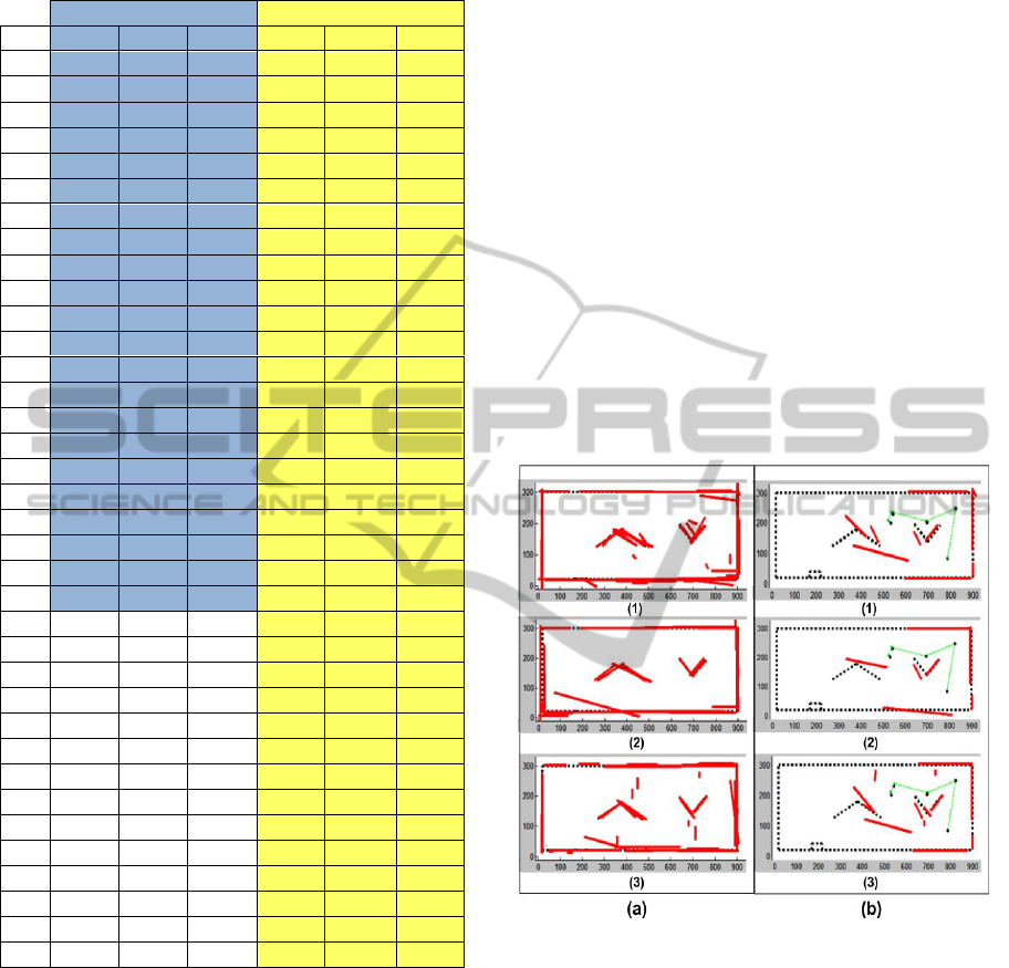
Table I: Absolute differences between estimated and real
robot poses (ΔX and ΔY in cm, ΔƟ in degree).
Without AEA
With AEA
POS
ΔX
ΔY
ΔƟ
ΔX
ΔY
ΔƟ
01
0.00
0.00
0.00
0.00
0.00
0.00
02
0.00
0.00
0.00
0.00
0.00
0.00
03
-1.00
-0.32
-2.00
0.51
0.15
1.85
04
-2.48
4.52
0.00
0.84
-2.72
1.47
05
-1.01
1.36
0.00
0.84
-2.72
1.42
06
-1.65
0.44
0.00
-3.29
-5.23
1.00
07
-3.33
0.81
-2.00
-0.21
0.85
2.98
08
1.85
-1.51
-3.04
-0.21
0.85
3.58
09
6.69
-1.63
0.00
-0.51
3.83
-1.85
10
2.86
-2.26
0.00
1.94
1.97
0.24
11
2.53
-0.20
-2.00
0.94
2.97
-0.24
12
2.94
1.92
3.00
0.28
2.96
-2.15
13
0.00
0.01
0.00
0.64
2.47
0.00
14
-0.67
1.99
0.00
0.64
2.47
0.00
15
-0.19
-0.70
-2.00
0.56
2.57
0.71
16
0.97
-4.01
0.00
0.56
2.57
0.10
17
2.86
-3.73
0.00
0.92
0.17
0.00
18
4.72
-2.97
0.00
0.92
0.17
1.00
19
4.50
-2.43
-1.00
2.36
3.77
3.03
20
0.07
0.05
0.43
2.36
3.77
1.77
21
-1.09
-0.04
-2.00
-1.76
4.84
2.99
22
1.36
-3.61
-1.84
-1.76
4.84
2.93
23
-2.39
2.91
3.12
24
-2.39
2.91
0.27
25
5.02
-1.83
0.99
26
6.35
-1.50
-0.06
27
4.44
-0.79
0.80
28
3.51
-2.20
-0.80
29
4.07
-4.05
3.39
30
1.62
3.22
3.13
31
-0.58
1.86
4.97
32
2.19
10.89
2.34
33
2.19
10.89
0.91
34
0.94
9.74
0.00
35
-1.43
7.67
0.99
36
-1.43
7.67
0.72
the actual environment area and others can be
viewed more length than the respective walls
inside the environment (Figure 8(b)). Once
again, this is not associated to employing AEA
and a possible solution to remove this mistakes
is evaluating feature crossing (inside and on
borders of the environment) based on the
estimated robot poses. If the segment
augmented in the feature crossing cannot be
perceived in any estimated robot pose (border
situations) or even if it occludes the previous
ones that were viewed in other estimated robot
poses (feature inside the environment), the
feature excess may be removed accordingly.
Although the estimated map without AEA
(Figure 8(a)) presents to be closer to the actual
environment than the one with AEA (Figure8(b)),
the fundamental reason to use the SLAM solution
with AEA approach is the robot´s autonomy,
avoiding human interventions as much as possible.
With some data produced in the experiment
without AEA (robot commands and sensor raw data
acquired in 22 position), one of the three sensors
available in SLAMVITA was “withdrawn”, just not
involving its data in the fusion algorithm. So, the
data (commands and raw data of the two “remained”
sensors) are used to verify if it is possible to validate
the solution to SLAM problem.
The experiments conducted for all combinations
of two SLAMVITA sensors with the total features
extracted by the proposed fusion algorithm
considering the robot real poses are shown in Figure
9(a), while the estimated map outputted by the
particle filter after the first six poses are presented in
Figure 9: (a) The total feature acquired by two
SLAMVITA sensors for all real robot poses; and (b) the
estimated map by the filter until robot pose #6 (1-visual
and sonar; 2- visual and infrared; and 3-infrared and
sonar). (b) Just few poses were sufficient to show that the
filter diverge for all cases.
When using the infrared and visual sensors (case
2, and so, not applying R1 and R3 rules) the overall
features appears with some distortions of the real
environment (Figure 9(a)), but with less feature
mistakes related to the others sensors combinations.
However, in all cases tested, the estimated map
(Figure 9(b)) is not consistent with the real one. In
the seventh robot pose the estimated and real ones
presented larger difference, leading the filter to
ICINCO 2012 - 9th International Conference on Informatics in Control, Automation and Robotics
412

begin diverge for all tested cases. These experiments
cannot be made using AEA, because it is based in an
incremental way which would lead the robot to
collide with the walls in the environment.
These experiments were important to show that
the SLAMVITA sensors disposition in the panning
turret and its simple types (visual, infrared and
sonar) allow solving the SLAM problem using a
low-cost mobile robot.
The proposed solution presented in this article in
comparison to others works that deal with indoor
SLAM using low-cost mobile robot, such as
presented by (Vazquez and Malcolm, 2005), does
not have restriction to navigate the robot nearby the
environment walls in function of the short
measurement range of the infrared sensors to build
the mapping environment. Moreover, only 4 sensors
are employed in SLAMVITA robot, and due to
theirs different principle of operations, the measure
noises can be solved by the proposed sensor data
fusion algorithm, mainly considering the
complementary fusion method. This is the case were
one of two directional sensor (vision or infrared) has
not measures at a specific angular area of the scan.
6 CONCLUSIONS
The environment mapping is an important task for
many purposes that the mobile robots might
perform, normally requiring sensor data fusion. A
mobile robot was constructed employing three
different sensor types: visual (wireless camera and
laser pointer), infrared (two units) and sonar.
This paper presents the tests of three software
modules that run in a cooperative way to solve the
indoor SLAM problem: a) a sensor data fusion
algorithm; b) a version of particle filter (FastSLAM
1.0); and c) an autonomous featured-based
exploration algorithm.
The results experiments presented show that
there are no significant differences when the
environment exploration task is performed with or
without autonomous exploration. In other word,
choose better positions to acquire the environment
measures are solved by proposed autonomous
algorithm. The estimated maps constructed by the
filter, which represent the environment, are
consistent for robot navigation purpose.
Currently the solution for a larger environment,
around 80 meters in length with some loop situations
is under development with satisfactory partial
results. The experiments in larger environments aim
to consistently validate all software modules
developed in this research. Both the estimated poses
and map must hold the consistency obtained in the
experiments presented in this article.
The main contribution of this research is to solve
the indoor SLAM problem using a low-cost mobile
platform that requires low computational load using
the overall system intelligence running in a PC
computer and embedded in the robot constructed
with simplified hardware and software.
REFERENCES
Aguirre, E., González, A., 2002. Integrating fuzzy
topological maps and fuzzy geometric maps for
behavior-based robots. International Journal of
Intelligent Systems, no. 17, pp. 333–368.
Buonocore, L., Nascimento Jr., C. L., Almeida Neto, A.,
2010. Sistema de baixo custo para medição de
distância em duas dimensões usando câmera IP sem
fio. 18º. Congresso Brasileiro de Automática, Bonito,
MS, Brazil, pp. 2239 – 2246.
Castellanos, J. A., Martínez, J. M., Neira, J., Tardós, J. D.,
1998. Simultaneous map building and localization for
mobile robots: a multisensor fusion approach.
International Conference on Robotics & Automation,
vol. 2, pp. 1244–1249.
Huge, D-W., 2001. Multi sensor data fusion. [e-book]
Available at: < http://www.acfr.usyd.edu.au/pdfs/ trai
ning/multiSensorDataFusion/dataFusionNotes.pdf>
[Acessed 12 September 2009].
Huge, D-W., Bailey, T., 2006. Simultaneous localization
and mapping: Part I. Tutorial. Robotics & Automation
Magazine, vol. 13, no. 3, pp. 99–108.
Ivanjko, E., Petrović, I., Brezak, M., 2009. Experimental
comparison of sonar based occupancy grid mapping
methods. AUTOMATIKA: Journal for Control,
Measurement, Electronics, Computing and
Communications, vol. 50, no. 1-2, pp. 65–79.
Milisavljević, N., Bloch, I., Acheroy, M., 2008. Multi-
sensor data fusion based on belief functions and
possibility theory: close range antipersonnel mine
detection and remote sensing mined area reduction. I-
Tech Education and Publishing, pp. 95–120.
Nguyen, H. G., Blackburn, M. R. (1995). A simple
method for range finding via laser triangulation,
Technical Document 2734, Naval Command, Control
and Ocean Surveillance Center RDT&E Division, San
Diego, CA.
Newman, P., Bosse, M., Leonard, J, 2003. Autonomous
feature-based exploration. International Conference
on Robotics and Automation, vol. 1, pp. 1234–1240.
Pandey, A. K., Krishna, K. M., Nath, M., 2007. Feature
based grid maps for sonar based safe-mapping.
International Joint Conferences on Artificial
Intelligence, pp. 2172–2177.
Thrun, S. B., 1993. Exploration and model building in
mobile robot domains. International Neural Networks,
vol. 1, pp. 175–180.
Solving the Indoor SLAM Problem for a Low-Cost Robot using Sensor Data Fusion and Autonomous Feature-based
Exploration
413

Thrun, S. B., Burgard, W., Fox, D., 2005. Probabilistic
Robotics. Cambridge, USA: MIT Press.
Vazquez, J., Malcolm, C., 2005. Fusion of triangulated
sonar plus infrared sensing for localization and
mapping. International Conference on Control and
Automation, vol. 2, pp. 1097–1102.
Visser, A., 1999. Chapter 9 - Sensor Data Fusion. [pdf]
Available at: < http://www.science.uva.nl/~arnoud/edu
cation/OOAS/fwi/Chap9.pdf> [Acessed 12 September
2009].
Yap Jr., T. N., Shelton, C. R., 2009. SLAM in large indoor
environments with low-cost, noisy and sparse sonars.
IEEE International Conference on Robotics and
Automation, Kobe, Japan, pp. 1395 – 1401.
Zuliani, M., 2009. RANSAC for Dummies-Draft. [pdf]
Available at: < http://vision.ece.ucsb.edu/~zuliani/Res
earch/RANSAC/docs/RANSAC4Dummies.pdf >
[Accessed 15 August 2009].
ICINCO 2012 - 9th International Conference on Informatics in Control, Automation and Robotics
414
