
Substations Optimization
Foundations of a Decision Making System
Luiz Biondi Neto
1
, Pedro H. G. Coelho
1
, Francisco Soeiro
1
, Osvaldo Cruz
1
and
David Targueta
2
1
State University of Rio de Janeiro, Av. Maracanã, 524, Rio de Janeiro, RJ, Brazil
2
São Simão M. S. Ltda, Mal Camara 160, Sala 1808, Rio de Janeiro, RJ, Brazil
Keywords: Decision Support System, Substations Optimization.
Abstract: The optimization of building processes for a power substation is based on the adopted configuration
structure and includes a simulation of the methods for the mechanical, civil and electrical processes. Thus it
is necessary to know the scope of the service area, the substation load and its connected transmission lines,
the terrain topography, and the environmental impact, issues that will be only known after the choice of the
area and the project details. The purpose of this work was to bring the foundations of a decision support
system regarding the reduction of the structure weight and its concrete volume. A laboratory reduction
model validated the work.
1 INTRODUCTION
For an electric utility, changes in legislation and
the growth of energy use require the need for new
tools and techniques, to achieve the highest level of
quality of power supply to the consumer at the
lowest cost and always preserving the environment.
For this reason, the research carried out, combines
mechanical civil and electrical engineering, and
therefore makes use of different methodologies,
depending on the area in which one seeks to
optimize envisioning a decision support system
(D’Ajuz, 1985).
The main objectives of this research aimed to
develop possible solutions for optimization of
construction of substations and consisted of:
1. Model and simulate the investigated metallic or
composite structures by estimating their weights,
aiming their reduction in the optimized Electrical
System (ES).
2. Shape the foundations of the pillars concerned to
the investigated metal or composite structures in
order to .reduce the concrete volume.
3. Model, simulate and test the Electrical System on
a reduced scale.
2 METHODOLOGY
2.1 Reducing the Weight Structure
Studies were undertaken in order to minimize the
weight of the structure with three different
situations, from the most traditional to the most
innovative on the market with technical
characteristics that meet the preliminary optimized
substation. Three structures were investigated:
1. Lattice-like structures (traditionally used).
2. Tubular structures (used in our proposal).
3. Centrifuged Concrete Structures (steel and
concrete).
These structures must be sized appropriately in order
to resist traction forces, self weight, weight of
equipment and wind acting on them.
For the calculations is necessary to know precisely
the topography of the region adjacent to the land and
own land for the construction, the angular
distribution lines related to the substation, and the
climatic characteristics of the region, especially in
relation to the wind, which at this stage project are
not yet defined.
The computational tool (Bhati, 2005) used to
model, simulate, analyze and estimate parameters in
the three cases studied, was the Finite Element
Method (FEM).
330
Biondi Neto L., H. G. Coelho P., Soeiro F., Cruz O. and Targueta D..
Substations Optimization - Foundations of a Decision Making System.
DOI: 10.5220/0004001603300333
In Proceedings of the 14th International Conference on Enterprise Information Systems (ICEIS-2012), pages 330-333
ISBN: 978-989-8565-10-5
Copyright
c
2012 SCITEPRESS (Science and Technology Publications, Lda.)
2.1.1 Lattice-like Structures
Lattice Systems are those consisting of
undeformable elements joined together by hinges,
considered perfect, and subject only to loads applied
to the joints or nodes. Thus the elements or bars are
only subject to normal efforts, traction or
compression. In the plane lattice, the set of
construction elements, e.g. round bars, flat or angles,
are interconnected under triangular form geometry,
by pins, welding, rivets or bolts, designed to form a
rigid structure in order to withstand only the normal
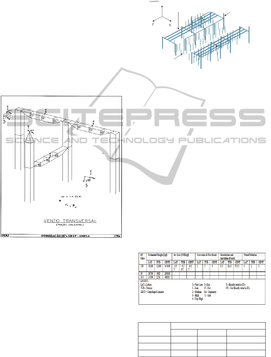
efforts. Figure 1 shows part of the plant that was
used for calculating the unilateral drift due to
crosswind for a 138 kV Electrical Substation.
Figure 1: Unilateral drift due to crosswind for a 138 kV
SE.
2.1.2 Tubular Structures
Tubular profiles can have three different geometries:
circular, rectangular and square. The geometry of
these profiles is their main advantage, because its
closed section allows a significant increase in
resistance. Besides, the effective reduction of the
foundations structure yields huge savings for these
buildings, and shows good integration to the
environment.
The circular profiles provide a better distribution
of stresses on the tube due to their geometry, in
which all cross-sectional points are equidistant and
therefore were investigated in our research. Figure 2
shows the FEM used in the 138 kV ES having
tubular structure.
Figure 2: FEM modelling used for tubular structure.
2.1.3 Centrifuged Concrete Structures
The excellent visual integration with the urban
environment, given the texture of the concrete and
the elegance of the structure, allows the installation
of centrifuged reinforced concrete in any area,
minimizing the impact on the environment and
landscape. Throughout this work simulations using
FEM were performed indicating that the weight of
the centrifuged reinforced concrete structure is much
larger than that of the tubular steel and the same
occurred with the lattice one. Consequently, the
amount spent on concrete foundations using
centrifuged concrete is much larger than the
structures used in tubular steel and the same
occurred with the lattice structure. Figure 3 shows a
brief view of a 138 kV Electrical Substation with
centrifuged concrete.
Tables I and II summarize some specifications,
technical and economic characteristics and important
peculiarities in these types of structures.
Table 1: Structures operational characteristics.
Table 2: Costs of the investigated structures.
kV Class
Structure Cost (US $)
Lattice Tubular Centrifuged
138 94935 54000 80556
69 72214 26910 111112
34.5 27559 10125 22223
Aluminum bus
φ
141,3 mm Larger columns φ 141,3 mm
Smaller columns
φ 60.3mm
Beams
φ 73 mm
SubstationsOptimization-FoundationsofaDecisionMakingSystem
331
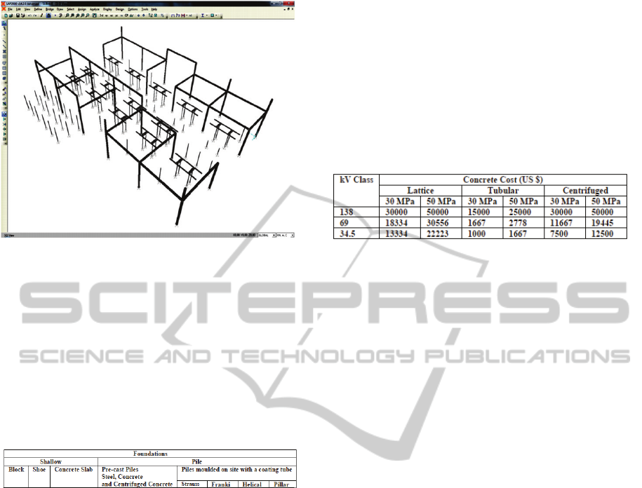
Figure 3: Centrifuged concrete structure for a 138 kV ES.
As far as the cost is concerned, the tubular
structure is also very attractive, as evidenced in
Table 2.
2.2 Simulation of the Concrete Volume
Generally, the foundations of substations can be
classified as shown in Table 3
Table 3: Foundations of substations types.
To accurately estimate the type and volume of
concrete foundations it is basically required to know
the loads to be transferred to the foundations of the
investigated structures, and evaluate the reports of
the land survey for the construction of the ES. It is
undeniable that there is an inevitable link between
the geological conditions and the design of the
foundations (Groenewald, 2009). Mentioned below
are some needs which must be fully met during the
detailed design of the project.
1. Definition of the loads to be transferred to
foundations;
2. Important developments in geomorphology;
3. Geotechnical local site;
4. Data on slopes and hillsides on the ground;
5. Data on erosion, occurrence of soft soil on the
surface;
6. Need to make cuts and embankments on the
ground;
7. Compressibility and resistance in the survey;
8. The level of groundwater;
9. Executive feasibility;
10. Economic viability.
It can be seen, through simulation, that the tubular
steel frame weighs less than 10% of the centrifuged
concrete structure and less than 25% of the lattice
structure, fact which would lead directly to its
choice. The lighter the structure, the lower the
concrete volume to be used, resulting in lower cost,
as shown in Table 4.
Table 4: Cost of concrete.
2.3 Reduced Model Testing
The choice of the reduction coefficient of the
reduced model was based taking into account not
only the physical limitations found in the Laboratory
of Structures and Materials (LEM) at PUC-Rio,
where tests were performed, but also the equipment
and instrumentation required to the tests, which
followed a high technical accuracy required in these
experiments and available on the LEM.
For the tests of the prototype scale model were
considered reductions in the dimensions of the parts,
taking into account the equivalence of physical
resistance to the tubes easily available for purchase
on the market. The height of the prototype is
decisive for the calculation of the reduction
coefficient under the penalty of exceeding the limits
permitted in the laboratory tests, which led to the
ratio of 1:6 (one to six).
The calculations of the reduced model were
based on the original study design. The values of the
geometric properties of the prototype, such as
length, width and height of the structure, and
external diameter and wall thickness of tubular
profiles were taken from the design of the 69 kV ES
performed using the structural analysis program
SAP2000. Figure 4 shows the model with the actual
dimensions.
All profiles are circular tubes with the following
dimensions:
Columns
• - outside diameter of 219.1 mm and 12.7 mm
thickness;
• - crossbeams - outside diameter of 219.1 mm and
12.7 mm thickness.
Longitudinal Beams
• - outside diameter of 101.6 mm and thickness 5.7
mm.
ICEIS2012-14thInternationalConferenceonEnterpriseInformationSystems
332
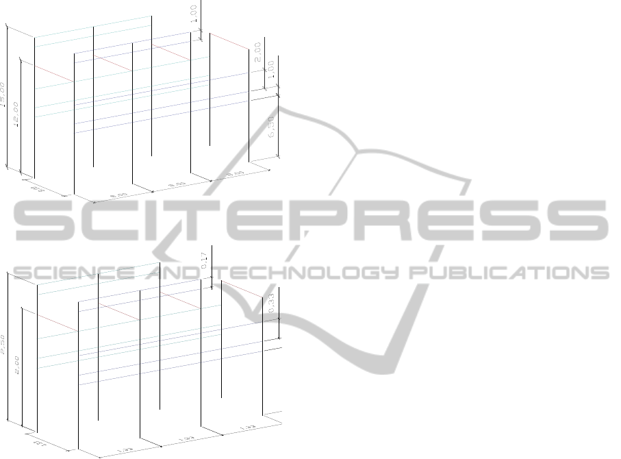
As explained earlier, the reduced model was
constructed using a reduction factor of 1:6. Figure 5
shows a schematic drawing of the dimensions of the
reduced model.
Figure 4: Actual dimensions of the 69 kV ES in meters.
Figure 5: Reduced Model Dimensions of the 69 kV ES
3 CONCLUSIONS
Under the specific viewpoint of optimization of
power substations, object of this research, the
obtained results seem very promising. For future
work it is intended to give more depth to the tubular
steel structures and their respective founding,
simulating more cases using finite element software,
in addition to those already made in this research.
The test results of the reduced model indicate
that the integrity of the structure was confirmed,
considering the details of the boundary conditions of
the investigated structures, loading and material,
where there was no need for any reinforcement or
modification of the original structure.
Finally, it was found that the optimized SEs were
actually efficient from the studied viewpoint.
REFERENCES
D’Ajuz, A., 1985. Electrical Equipments – Specifications
and Applications in High Voltage Substations,
Furnas/UFF Ed., in Portuguese.
Bayliss, C. and Hardy, B., 2007. Transmission and
Distribution Electrical Engineering, Newness Ed.
Bhatti, M. A., 2005. Fundamental Finite Element Analysis
and Applications with Mathematica and Matlab
Computations, John Wiley & Sons.
Groenewald, A., J., S., 2009. The Use of Tubular
Conductors in the Design of High Voltage
Substations. In CIBRE 6
th
S. Africa Regional Conf.,
2009.
Carneiro, F., L., 1996. Dimensional Analysis and
Similarity and Physical Models Theory, UFRJ Ed., in
Portuguese.
SubstationsOptimization-FoundationsofaDecisionMakingSystem
333
