
A Formal Compositional Verification Approach for Safety–Critical
Systems Correctness
Model–Checking based Methodological Approach to Automatically Verify Safety
Critical Systems Software
Manuel I. Capel
1
and Luis E. Mendoza Morales
2
1
Department of Software Engineering, University of Granada, Informatics & Telecommunications, 18071 Granada, Spain
2
Processes and Systems Department, Sim´on Bol´ıvar University, P.O. box 89000, Baruta, Caracas 1080-A, Venezuela
Keywords:
Safety–Critical Systems, Compositional Verification, Model–Checking, Software Specification, Software
Verification, Methodological Approach.
Abstract:
The complexity of modern Safety–Critical Systems (SCS) together with the absence of appropriate software
verification tools is one reason for the large number of errors in the design and implementation of these sys-
tems. Moreover, exhaustive testing is hard and highly complex because of the combinatorial explosion in the
great number of states that an SCS can reach when it executes. A methodological approach named FCVA that
uses Model–Checking (MC) techniques to automatically verify SCS software is presented here. This approach
facilitates decomposition of complex SCS software into independently verified individual components, and
establishes a compositional method to verify these systems using state–of–the–art MC tools. Our objective
in this paper is to facilitate the description of an SCS as a collection of verified components, allowing com-
plete complex SCS software verification. An application on a real–life project in the field of mobile phone
communication is discussed to demonstrate the applicability of FCVA.
1 INTRODUCTION
The ever increasing complexity of current software
systems has reached application areas where the trust-
worthiness of a computing system must guarantee the
reliance on the service it delivers. Safety–Critical Sys-
tems (SCS), including energy production, automotive,
medical systems, avionics and modern telecommu-
nications are typical industrial systems where avail-
ability, performance, safety, integrity, maintainabil-
ity, real–time response are crucial. All the above fea-
tures are included in the computer systems concept of
dependability
1
. New verification methods and soft-
ware tools for “design prediction” of dependabilityat-
tributes of SCS are being intensely investigated now.
Thus, this paper proposes a compositional scheme
that can be applied to the verification of properties
that express the certainty of a future event or system
action (safety), or to verify that the system is not un-
dergoing a deadlock situation or to affirm that every
needed state of the system must eventually entered in
1
See IEC IEV 191-02-03, IFIP 10.4 Working Group on
Dependable Computing and Fault Tolerance.
an infinite computation (fairness).
Deductive techniques combined with advanced
Model–Checking (MC) techniques are seen as the sil-
ver bullet to face the enormous complexity of SCS
verification (Hooman, 1991; de Roever et al., 2001).
However, it is not a simple task to export local ver-
ification results using a formal deductive language,
such as Predicate Logic, including conjunctivepropo-
sitional logic operators and, at the same time, to pre-
serve the semantic correctness of the automatically
performed proofs of verified system’s components.
Formal Compositional Verification Approach
(FCVA) is proposed here to verify a SCS from in-
dividual components (Mendoza and Capel, 2009),
based on a conceptual framework that transforms
a graphical oriented model of the system and its
properties into a specific process calculus. FCVA
offers a methodological infrastructure for composi-
tional verification made up of: (1) a formal speci-
fication/modelling notation supported by CSP–based
(Schneider, 2000) compositional reasoning that en-
ables the preservation of the component properties,
and (2) “conceptual hooks” that facilitate the integra-
tion of CSP–based model–checkers into the verifica-
105
I. Capel M. and E. Mendoza Morales L..
A Formal Compositional Verification Approach for Safety–Critical Systems Correctness - Model–Checking based Methodological Approach to
Automatically Verify Safety Critical Systems Software.
DOI: 10.5220/0004003801050112
In Proceedings of the 14th International Conference on Enterprise Information Systems (ICEIS-2012), pages 105-112
ISBN: 978-989-8565-11-2
Copyright
c
2012 SCITEPRESS (Science and Technology Publications, Lda.)

tion process of the entire system. FCVA variants can
be applied to modelling timed and untimed systems.
The untimed infinite traces is used for the analysis of
liveness properties, which may contain failures.
In the following section, the formal background to
our approach is described. Afterwards, the conceptual
framework behind the FCVA is presented. Thereafter,
a real–life project regarding mobile phone communi-
cations that has to meet critical time requirements. Fi-
nally, our conclusions and future work are discussed.
2 FORMAL BACKGROUND
The essence of safety–critical processes behaviour
and the sequence and communication synchroniza-
tion that it should represent are described by CSP and
CSP+T models in our proposed method.
SKIP :≡ success (successful termination)
STOP :≡ deadlock
t
a
.a → P :≡ t
a
.a then P (prefix)
t0.⋆ →
e
P :≡ (⋆ ∧ s(⋆) = t0) then
e
P
(process instantiation)
t
a
.a ⋊⋉ v → P :≡ (t
a
.a∧ s(a) = t
a
) then P
(marker variable)
P#Q :≡ P (successfully) followed by Q
(sequential composition)
P⊓ Q :≡ P or Q
(non–deterministic)
PQ :≡ P choice Q
(deterministic or external choice)
P\A :≡ P without A
(hidding)
P△Q :≡ P interrupted by Q
I(T,t
1
).a → P :≡ (t
a
.a∧t
a
∈ [rel(t
1
,v),
rel(t
1
+ T,v)]) then P
(event–enabling interval)
I(T,t
1
) →
e
P :≡ t > rel(t
1
+ T,v) then
e
P (delay)
PkQ :≡ P in parallel with Q
(parallel composition)
P|[A]|Q :≡ P in parallel with Q in alphabet A
(alphabetized composition)
P9Q :≡ P interleave Q (interleaving)
I(T
a
,t
a
).a → P|[A]| :≡ PkQ
if (a = b) ∧ (I(T
a
,t
a
) ∩ I(T
b
,t
b
) 6=
/
0)
I(T
b
,t
b
).b → Q P9Q
if (a 6= b) ∧ (I(T
a
,t
a
) ∩ I(T
b
,t
b
) 6=
/
0)
STOP if I(T
a
,t
a
) ∩ I(T
b
,t
b
) =
/
0
µX@P :≡ the process X such that X = P(X)
(recursion)
e
m
i=1
: N • P(i) :≡ i : N → P(i)
(external choice indexed)
d
m
i=1
: N • P(i) :≡ P((τ−)action)
(internal choice indexed)
g
m
i=1
: N • P(i) :≡ i : N →
g
m
i=1
P(i)
(indexed interleaving)
f
m
i=1
[A] : N • P(i) :≡ i : N →
f
m
i=1
P(i)
(partial interleaving)
f
m
i=1
: N • A(i) ◦ P(i) :≡ i : N →
f
m
i=1
A(i) ◦ P(i)
(parallel combination of processes)
CSP+T Syntax Rules
{ϕ,¬ψ}
S
1
{ψ}
S
2
[a+1,b]
{}
S
0
[a,b-1]
[a+1,b-1]
[a+2,b]
Figure 1: CCTL formula.
2.1 Specification of the System Model
CSP+T (Zic, 1994) is a real–time specification lan-
guage which extends Communicating Sequential Pro-
cesses (CSP) allowing the description of complex
event timings, within a single sequential process.
A CSP+T process term P is defined as a tu-
ple (αP, P), where αP = Comm act(P) ∪ Inter f ace(P)
is called the communication alphabet of P. These
communications represent the events that process P
receives from its environment or those that occur in-
ternally. CSP+T is a superset of CSP, the latter being
changed by the fact that traces of events become pairs
denoted as t.a, where t is the time at which event a is
observed. where a, ⋆ ∈ Σ (communication alphabet);
A,N ⊆ Σ; v ∈ M (marker variables); I ∈ I (time in-
tervals); P,Q,X,
e
P ∈ P (process names); t
0
,t
a
,t
1
∈ T ;
and T ∈ N (time instants), and the function s(t
a
.a)
which return the occurrence time of symbol a.
The event enabling interval I(T,t
a
) = {t ∈
T |rel(t
a
,v) ≤ t ≤ rel(t
a
+ T,v)} indicates the time
span where any event is accepted. rel(x,v) = x +
v − t
0
, t
0
corresponds to the preceding instantiation
event (⋆), occurred at some absolute time t
0
, and x
is the value held in the marker variable v at that
time. The time interval expression can be simplified
to I(T,t
a
) = [t
a
,t
a
+ T] if the instantiation event, after
which the event a can occur, corresponds to the origin
(t
0
= 0) of the real–time clock.
2.2 Abstract Specification of the
Properties
Property specification languages are used to obtain a
formal specification of the expected SCS behaviour
according to the user requirements. CCTL (Ruf and
Kropf, 1997) is a temporal interval logic that ex-
tends Computation Tree Logic (CTL) (Clarke et al.,
2000) with quantitative bounded temporal operators,
i.e., temporal operators interpreted over time inter-
vals. CCTL includes CTL with the operators until
(U) and the operator next (X) and other derived op-
erators in LTL, such as release (R), weak until (W),
cancel (C) and since (S). All “LTL-like” temporal op-
ICEIS2012-14thInternationalConferenceonEnterpriseInformationSystems
106
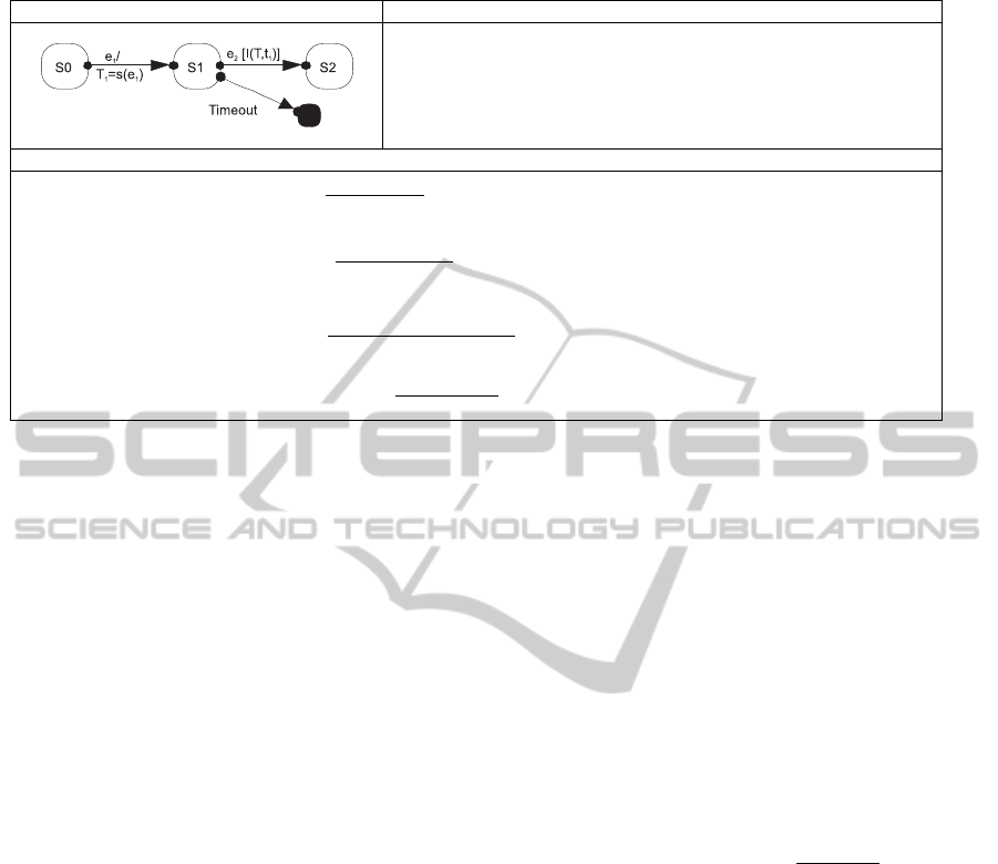
Table 1: Example of a map rule from UML–TSM to CSP+T terms.
UML–TSM Description
The state S1 precedes the state S2 and these states are reached when events e
1
and e
2
occur, respectively. But to reach the state S2, the event e
2
(restricted event) must occur
within the time interval [T1, T 1 + T] (event–enabling interval), where T
1
is the maker
variable of the event e
1
(marker event). If the restricted event e
2
does not occur within
the time interval [T1, T1+ T] (i.e., the event–enabling interval completely runs), then
reaches a pseudostate Timeout. T
1
,T ∈ N
∗
(i.e., natural numbers without zero).
CSP+T Structural Operational Semantics
1. e
1
occurrence)
S1=e
1
⋊⋉t
1
→S2
t
1
=s(e
1
); S2
S1,S2 ∈ states;
s(e
1
)
2. e
2
occurrence)
S2=I(T,t
1
).e
2
→S3
s(e
2
); S3
s(e
2
) ∈ [t
1
,t
1
+ T];
S2,S3 ∈ states
OR
I(T,t
1
) timeout)
S2=I(T,t
1
)→Timeout→SKIP
s(τ); Timeout→SKIP
s(τ) < t
1
+ T;S2 ∈ states;
Timeout ∈ pseudostates
Timeout execution step)
Timeout→SKIP
s(τ); SKIP
s(τ) = t
1
+ T;
Timeout ∈ pseudostates
erators are preceded by a run quantifier (A universal,
E existential) which determines whether the temporal
operator must be interpreted over one run (existential
quantification) or over every run (universal quantifi-
cation). These temporal operators start in the current
configuration. For instance, let φ be the CCTL for-
mula (1) which states that ψ must become true within
the interval [a,b] and, that the formula ϕ must be valid
at all previous time steps. The CCTL formula φ, ex-
pressed as a B¨uchi automaton in Figure 1, is therefore:
φ = ϕU
[a,b]
ψ . (1)
2.3 Transformation Rules
The formalisation of UML–RT given by
MEDISTAM–RT (Benghazi et al., 2007) is of
interest here because it allows us to obtain and verify
a SCS model from UML diagrams. MEDISTAM–RT
(Spanish acronym of Method for System Design
based on Analytic Transformation of Real–Time
Models) can be described as a series of system views
represented by UML for Real Time (UML–RT),
with class diagrams, composite structure diagrams,
and UML timed state machines (UML–TSM). The
expressiveness of UML–TSM is augmented by in-
cluding new constructs adopted from CSP+T syntax,
such that TSMs make now possible to model timing
issues and time dependencies among tasks.
Table 1 shows a graphical example of the transfor-
mation rules application for obtaining CSP+T process
terms from UML–TSMs. We will only present one of
the proposed rules, mainly to demonstrate the appli-
cability of FCVA and to show that our approach can
be integrated to MC tools like FDR2. A complete de-
scription of the system of transformation rules can be
found in (Benghazi et al., 2007). The transformation
is performed by mapping (1) every UML–TSM state
to a CSP+T process term, (2) every transition to a pre-
fixed CSP+T process, (3) every discrete time guard to
a CSP+T event–enabling interval, and (4) two or more
outgoing transitions to two or more prefixed CSP+T
process separated by an external choice operator.
We define the transformation rules according to
the Structural Operational Semantics (SOS), which
is usually used to formally describe the semantics
of programming languages. SOS is compositional,
because it allows the semantics of complex process
terms to be defined from simpler ones.
The application of the transformation rules’ pat-
tern:
event/communication/executionstep)
premises
conclusion
(conditions)
can be understood as a transformation between two
syntactical terms that occur as a consequence of a
communication between concurrent processes or an
execution step or event occurrence in a sequential pro-
cess. Thus, each rule defines the premises of the
UML–RT element to be transformed and the condi-
tions that must be satisfied before transforming the
referred element into the syntactical CSP+T process
term indicated in the conclusion of the rule.
3 COMPOSITIONAL
VERIFICATION OF SCS
Compositional verification of properties for a given
temporal logic has recently been studied intensively
by several authors (Giese et al., 2003; Rabinovich,
AFormalCompositionalVerificationApproachforSafety-CriticalSystemsCorrectness-Model-Checkingbased
MethodologicalApproachtoAutomaticallyVerifySafetyCriticalSystemsSoftware
107

2007; de Roever et al., 2001) in order to achieve prac-
tical application of MC techniques to the verification
of software systems. Temporal Logic (TL) formulas
that express the possibility of entering in a state in
the future (reachability), or properties expressing live-
ness, are not preserved by compositionality (Table 2).
Table 2: Verification–compositionality (VC) of different
properties, see (Rabinovich, 2007).
Name TL–denotation Fulfils VC?
Safety AG Yes
Liveness AG(req → AFsat) No
Reachbility EFφ No
Deadlock freeness AGEXtrue Yes
Fairness AGAFφ Yes
3.1 Compositional Verification of a
Concurrent System
In a formal way, the system model C is assumed to
be structured into several verified software compo-
nents working in parallel, i.e., C =
f
i:1..n
C
i
, where
each C
i
satisfies the property φ
i
, i.e., C
i
φ
i
, which
represents the specification of the expected behaviour
of the component. Regarding the proposed decompo-
sition strategy, we assume that C can be decomposed
until a set of components, whose behaviour can be
specified using a TSM, is found. In addition to the
local properties φ
i
, each C
i
must also satisfy the in-
variant expression ψ
i
that represents the behaviour of
other system components with respect to C
i
. Since,
according to (Abadi and Lamport, 1995), to verify the
property φ
i
of componentC
i
we need to assume some
kind of behaviour of the other components (i.e., ψ
i
).
Theorem 1. System Compositional Verifica-
tion. Let the system C be structured into
several components working in parallel, C =
f
i:1..n
C
i
. For a set of TSM(C
i
) describing the
behaviour of componentsC
i
, properties φ
i
, in-
variants ψ
i
, and deadlock δ, with
T
i:1..n
Σ
i
=
/
0,
T
i:1..n
Ω
i
=
/
0, and
T
i:1..n
L (TBA(C
i
)) =
/
0,
the following condition holds:
TSM(C) (φ∧ ψ ∧ ¬δ) ⇔
n
i:1..n
TSM(C
i
)
^
i:1..n
(φ
i
∧ ψ
i
) ∧ ¬δ,
(2)
where TBA(C) = k
i:1..n
TBA(C
i
).
3.1.1 Interpretation of SCV Theorem
If the properties used to specify the system compo-
nents are circumscribed to the class of composable
properties for verification (see Table 2), then prop-
erty φ and the invariant ψ that are satisfied by the sys-
tem C can be obtained by conjunction of local prop-
erties φ
i
(i.e.,
V
i:1..n
φ
i
⇒ φ) and invariants ψ
i
(i.e.,
V
i:1..n
ψ
i
⇒ ψ), respectively. The special symbol ¬δ
is used to denote deadlock absence, i.e., a state with-
out any outgoing transition cannot be reached on any
system execution.
A more complete description and practical aspects
of our conceptual scheme are detailed in (Mendoza
and Capel, 2009).
3.2 Formal Compositional Verification
Approach
The rationale of FCVA is that the behavioural correct-
ness of SCS software components can be individu-
ally verified, in isolation, based on Theorem 1 and
the well–defined communicationsbehaviour specified
by MEDISTAM–RT capsule component (Benghazi
et al., 2007). FCVA uses the CSP+T specification lan-
guage, which has a simple but powerful form of com-
position given by concurrent composition and hiding
operators, to describe formally capsules and TSM di-
agrams. And thus, the automata interpretation, intrin-
sic to the use of CSP–like notation, allow us to imple-
ment complex system behaviour in a easy and direct
way (Schneider, 2000). CSP+T–based language al-
lows us to calculate initial events of any syntactical
process term as well as when the events occur and
what the process is doing after the event occurrence.
Methodologically, our approach establishes that
both the formal description of the system’s behaviour
and the specification of its properties must be directed
by the system’s user requirements. And thus, FCVA
consists of the following integrated processes accord-
ing to MC technique and the automata theory,
System Interpretation. Firstly, the complete de-
scription of the system’s behaviour, modelled by
the CSP+T process term T(C) is interpreted into
a set of CSP+T process terms T(C
i
) by using
MEDISTAM–RT. In (Benghazi et al., 2007), the
modelling process is detailed.
Properties Specification. Then, requirements and
temporal constraints that the system must fulfill
are specified in CCTL, which is based on the in-
terval structure and time–annotated automata (Ruf
and Kropf, 1997). Afterwards, these properties
are expressed by CSP+T process terms T(φ
i
),
T(ψ
i
), T(¬δ), following the algorithm described
in (Mendoza and Capel, 2009) and then applying
the procedure also presented here.
ICEIS2012-14thInternationalConferenceonEnterpriseInformationSystems
108

Verification. Finally, we proceed to verify the sys-
tem behaviour component-by-component.
Thus, we use formal specification/modelling nota-
tions supported by CSP–based compositional reason-
ing that enables the preservation of the component
properties throughout the compositionality.
4 APPLICATION
The application of FCVA presented here relates to
monitoring the state of mobile devices within the cells
that constitute a mobile phone communication net-
work. We present here a real–life scenario where a
series of BTSs
2
exchange messages between them,
i.e., send message, SndMsg(s); acknowledgement
message, AckMsg(s); and receive confirmation, Rcv-
Conf(s). The DDBM model represents the function-
ing of a small distributed database system, which is
needed to keep consistent the communication infor-
mation locally stored in the base stations.
To understand this model of protocol, we need to
think of it as a set of finite state automata with symme-
tries. Each automaton represents n symmetric repli-
cated automata that describe the states of the n man-
agers d
i
and the state of the messages transmitted by
each d
i
during DDBM protocol functioning. The tran-
sitions that each automaton must undergo are named,
‘Update and Send Messages’, ‘Receive a Message’,
‘Send an Acknowledgement’ and ‘Receive All Con-
firmations’ (Jansen, 1997).
4.1 Properties & Software Specification
The complete set of CCTL formulas that formally de-
fine the properties fulfilled by the DDBM model’s be-
haviour are detailed in (Mendoza and Capel, 2009)
and derived from user’s requirements. Since the
DDBM protocol model is conformed by n replicas of
the same component (i.e., DDBM = k
i:1..n
d
i
), the in-
variant ψ
i
that each component d
i
must satisfy is the
conjunction of the replicas properties, but without it-
self, i.e., ψ
i
=k
j:1..n
φ
j
| j 6= i. Thus, at this stage, we
only need to address the verification of local proper-
ties φ
i
.
We can use an RT-software design method like
MEDISTAM–RT (Benghazi et al., 2007), which in-
troduces temporal annotations to UML–TSM to for-
mally describe the protocol (Figure 2). Time labels
on the state machines are necessary to assure the ful-
filment of maximum time constraints that the real–
time DDBM protocol requires. By using these inter-
2
Base Transceiver Stations
val and time instants specifications, we can guarantee
that none of the d
i
managers will enter in a blocking
state and new occurrences will be disregarded.
4.2 System Components Verification
Once we have obtained the automata,
• T(d
i
), T(AC),T(MM), which represent system
components, DDBM manager, Act Control, and
Message Manager (Figure 2), respectively.
• As well as the ones corresponding to the proper-
ties, T(φ
RUAC
), T(φ
RUMM
), T(φ
LUAC
), T(φ
LUMM
)
(Mendoza and Capel, 2009).
We can proceed to the verification of the DDBM sys-
tem, component by component.
Then, under the semantic domain of CSP–based
process calculus, we can automatically check with the
help of FDR2 (Formal Systems Europe Ltd., 2005)
tool that the following relations of refinement are sat-
isfied:
T(φ
LUAC
) ⊑
T
T(AC) , T(φ
RUAC
) ⊑
T
T(AC)
T(φ
LUAC
) ⊑
F
T(AC) , T(φ
RUAC
) ⊑
F
T(AC)
T(φ
LUMM
) ⊑
T
T(MM) , T(φ
RUMM
) ⊑
T
T(MM)
T(φ
LUMM
) ⊑
F
T(MM) , T(φ
RUMM
) ⊑
F
T(MM)
We say that there is a refinement relation between
two formal automata T(φ) ⊑
T
T(Component) if ev-
ery trace of executionof T(Component) is included in
the set of traces and failures that defines the behaviour
of the automaton T(φ) (Schneider, 2000).
According to the conditions of System Composi-
tional Verification Theorem 1 (see section 3.1), and
based on the detailed design of Act Control and
Message Manager components shown in Figure 2,
we must determine now whether the individual ver-
ification of these components is “composable”. We
must verify that the following 2 conditions of Theo-
rem 1 are always fulfilled:
1. The input signals (Σ
Act Control
and
Σ
Message Manager
) and the output signals
(Ω
Act Control
and Ω
Message Manager
) of both
components are disjoint. The encapsulation of
the automata that only communicate through ded-
icated input/output ports ?m and !m, respectively,
makes this condition always true.
2. The labelling sets of both components
L (Act Control) and L (Message Manager)
are disjointed. This can also be easily verified
since transition and state labels of each automaton
are only visible inside the capsule.
The main interest of Theorem 1 is to address the
difficult problem of proving that the satisfaction of
AFormalCompositionalVerificationApproachforSafety-CriticalSystemsCorrectness-Model-Checkingbased
MethodologicalApproachtoAutomaticallyVerifySafetyCriticalSystemsSoftware
109
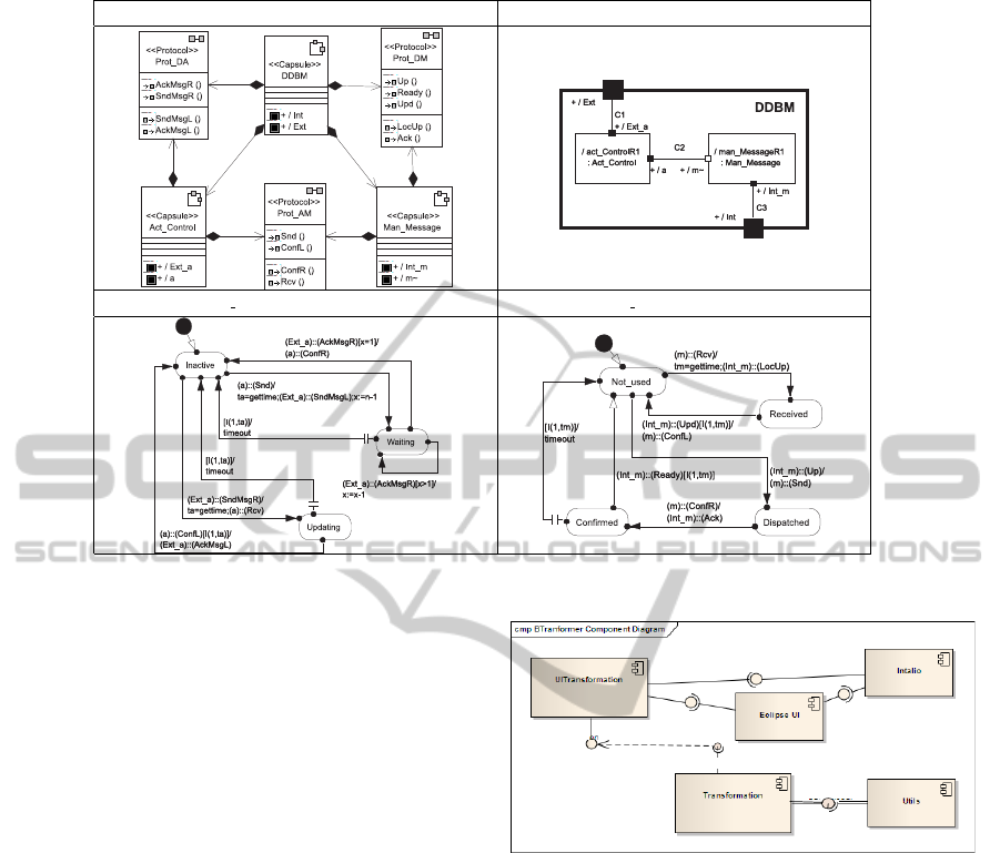
Class diagram (a) Composite structure diagram (b)
Act Control UML–TSM (c) Message Manager UML–TSM (d)
Figure 2: Software Architecture of the DDBM Model with MEDISTAM–RT.
a complex property of the system can be determined
by the individual verification of simpler properties of
its components and the rules used to combine them.
In our case, the proposed adaptation of (Abadi and
Lamport, 1995) Theorem has as its most important
consequence the fact that compositional verification
of an SCS becomes reduced to proof the reliability
of a communication protocol between deterministic
CSP+T processes with interfaces and communication
alphabets previously defined.
4.3 BTRANSFORMER Tool
The main objective of BTRANSFORMER tool is to
generate a CSP+T specification from UML–TSM dia-
grams of any reactive system. In previous work (Men-
doza et al., 2012), we have improved the semantic
proposed in (Wong and Gibbons, 2009) by incorpo-
rating the CSP+T operators, which allow the defi-
nition of a timed semantics of TSM and Composite
Structure Diagrams of UML/MEDISTAM–RT.
4.3.1 BTRANSFORMER Properties
Developed using Open Unified Process (OpenUP)
methodology(Eclipse.org), BTRANSFORMER has the
capability to read input/output models written in stan-
dard XML and it can be used with different operating
systems: Windows, Linux and MacOS. It allows the
analyst to have access to the TSM2CSP menu options
MEDISTAM-TSM Model
CSP+TModel
TSM2CSPAction
RequiredInterface
TSM2CSP Menu
TSM Editor
Figure 3: BTRANSFORMER tool components.
for creating and editing UML–TSM to CPS+T trans-
formation rules.
All the plugins needed to implement BTRANS-
FORMER (Figure 3) are based on the Eclipse plat-
form, especially those that allow the implementation
of the interfaces. The integration of transformation
languages was achieved with the editor
Intalio
, also
integrable with the Eclipse platform.
The plugin
Intalio
controls the entire modelling
process from the initial source model (including tem-
poral annotations on TSMs) and helps to integrate
the transformation notations. In its part, the plugin
Utils
handles the reading of MEDISTAM–RT mod-
elling entities in the source model and helps to write
CSP+T processes in the object model.
4.3.2 Preliminary Tests
CSP+T models yielded by BTRANSFORMER were in-
ICEIS2012-14thInternationalConferenceonEnterpriseInformationSystems
110
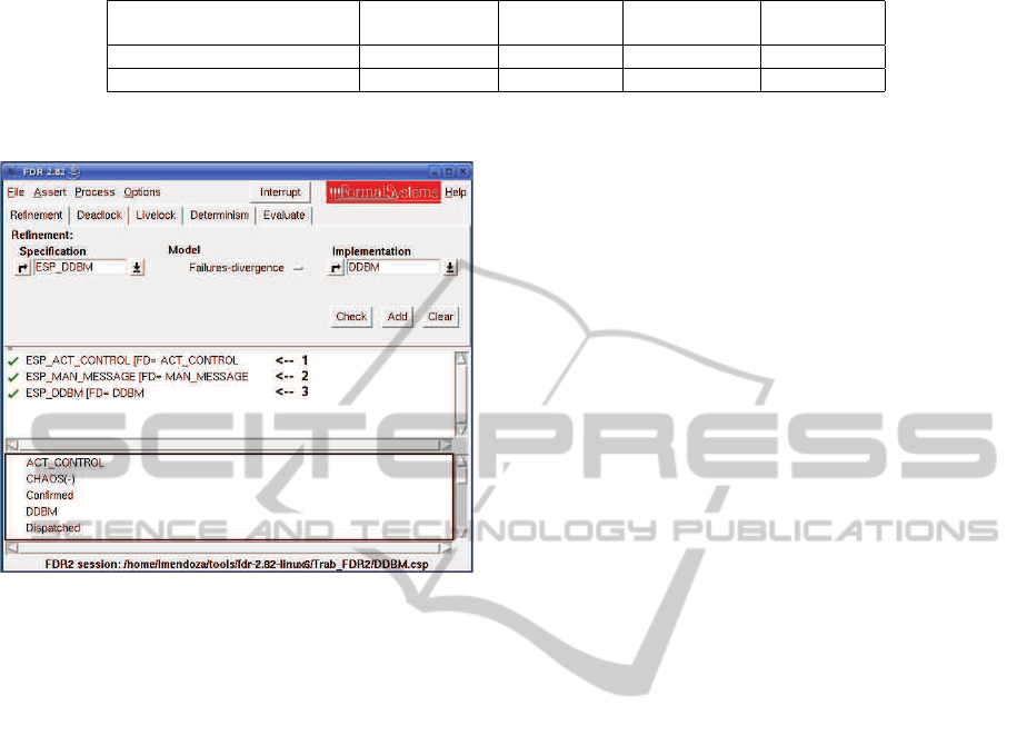
Table 3: Results of preliminary tests.
Model Completeness Number Completeness Behavioural
of elements of processes of relation safety
Transport Chain Yes 12 Yes Yes
Logistic process in hospitals Yes 22 Yes Yes
Figure 4: FDR2 screenshot.
put (Figure 4) to FDR2 model–checking tool (For-
mal Systems Europe Ltd., 2005) to check semantic in-
consistencies in syntactical process terms. The cases
used to assess the operation of the tool were Transport
chain (Koniewski et al., 2006) and Logistics process
in hospitals (Baacke et al., 2009). In addition, the
following criteria were defined in order to detect in-
consistencies between source (MEDISTAM–RT) and
target (CSP+T) models.
a. Completeness of elements. All elements of source
diagrams appear reflected in their semantically
equivalent specifications in CSP+T.
b. Number of processes. There is at least one CSP+T
process for each activity defined in the diagram.
c. Completeness of relations. It is possible to estab-
lish a relation between two processes as long as
they present a previous relation between two or
more activities in the model.
d. Behavioral safety. Thus, it has been made sure
that the CSP+T model does not “invent” execution
sequences which do not exist in the source model.
According to the results of Table 3, we can af-
firm that in both cases the generated specification was
complete, and met the minimum expected of process
definitions. Relations were also reflected in the spec-
ification and behavioral safety is preserved.
5 CONCLUSIONS
In this paper we have presented FCVA for composi-
tional software verification from independently veri-
fied individual components. MC was used to prove
the correctness of individual components and a CSP–
based process calculus inspired formal language was
integrated in order to foster the composition of SCS,
aided by concurrent composition operators.
We have shown the value and practicality of our
approach by means of the application to a real–life
project in the field of mobile communications, which
has to meet time critical requirements. The CSP+T
specification of the system components at the design
phase can be verified against the CCTL specification
of the individual system component properties.
ACKNOWLEDGEMENTS
We would like to thank A. Gonz´alez from Sim´on
Bol´ıvar University in Caracas (Venezuela) for imple-
menting the BTRANSFORMER in the Eclipse plat-
form.
REFERENCES
Abadi, M. and Lamport, L. (1995). Conjoining specifica-
tions. ACM TOPLAS, 17(3):507–535.
Baacke, L., Mettler, L., and P.Rohner (2009). Component–
based process modelling in health care. 17th Europ.
Conference on Information Systems, 1(a):507–535.
Benghazi, K., Capel, M., Holgado, J., and Mendoza, L.
(2007). A methodological approach to the formal
specification of real–time systems by transformation
of uml-rt design models. Science of Computer Pro-
gramming, 65(1):41–56.
Clarke, E., Grumberg, O., and Peled, D. (2000). Model
Checking. The MIT Press, Cambridge, USA.
de Roever, W., de Boer, F., Hannemann, U., Hooman, J.,
Lakhnech, Y., Poel, M., and Zwiers, J. (2001). Con-
currency Verification: Introduction to Compositional
and Noncompositional Methods, volume 54 of Cam-
bridge Tracts in Theoretical Computer Science. Cam-
bridge University Press, Cambridge, UK.
Formal Systems Europe Ltd. (2005). Failures–Divergence
Refinement – FDR2 User Manual. Formal Systems
Europe Ltd., Oxford.
AFormalCompositionalVerificationApproachforSafety-CriticalSystemsCorrectness-Model-Checkingbased
MethodologicalApproachtoAutomaticallyVerifySafetyCriticalSystemsSoftware
111

Giese, H., Tichy, M., Burmester, S., and Flake, S. (2003).
Towards the compositional verification of real–time
UML designs. In ESEC/FSE–11: Proc. 9th Euro-
pean Software Engineering Conference held jointly
with 11th ACM SIGSOFT International Symposium
on Foundations of Software Engineering, pages 38–
47, New York, USA. ACM Press.
Hooman, J. (1991). Specification and Compositional Veri-
fication of Real–Time Systems, volume 558 of LNCS.
Springer–Verlag, Berlin, Germany.
Jansen, K. (1997). Coloured Petri Nets. Springer–Verlag
Inc., New York, USA.
Koniewski, R., Dzielinski, A., and Amborski, A. (2006).
Use of petri nets and business processes management
notation in modelling and simulation of multimodal
logistics chains. In 20th European Conference on
Modelling and Simulation, Barcelona, Spain.
Mendoza, L. and Capel, M. (2009). Automatic composi-
tional verification of business processes. Enterprise
Information Systems, LNBIP, 24:479–490.
Mendoza, L., Capel, M., and P´erez, M. (2012). Con-
ceptual framework for business processes composi-
tional verification. Information & Software Technol-
ogy, 54(2):149–161.
Rabinovich, A. (2007). On compositionality and its limita-
tions. ACM TOCL, 8(1):1–26.
Ruf, J. and Kropf, T. (1997). Symbolic model checking for
a discrete clocked temporal logic with intervals. In
Proc. of the IFIP WG 10.5 International Conference
on Correct Hardware Design and Verification Meth-
ods, pages 146–163.
Schneider, S. (2000). Concurrent and Real–Time Systems –
The CSP Approach. John Wiley & Sons, Ltd.
Wong, P. and Gibbons, J. (2009). A relative timed semantics
for bpmn. Electronic Notes in Theoretical Computer
Science, 229(2).
Zic, J. (1994). Time–constrained buffer specifications in
CSP+T and Timed CSP. ACM TOPLAS, 16(6):1661–
1674.
ICEIS2012-14thInternationalConferenceonEnterpriseInformationSystems
112
