
A Model-based Approach for Reusing Crosscutting Frameworks
Thiago Gottardi
1
, Oscar L´opez Pastor
2
and Valter Vieira de Camargo
1
1
Departamento de Computac¸˜ao, Universidade Federal de S˜ao Carlos (UFSCar),
Rodovia Washington Luiz 235, S˜ao Carlos, Brazil
2
Departamento de Sistemas Inform´aticos y Computaci´on, Universidad Politecnica de Valencia,
Camino de Vera s/n, Valencia, Spain
K
eywords:
Model-driven Engineering, Framework Reuse, Aspect-oriented Programming, Crosscutting Framework,
Empirical Study.
Abstract:
The development of large enterprise information systems usually encompass the adoption of many infras-
tructure frameworks, e.g. persistence, authentication, concurrency and distribution. Although reusing these
functionalities improve the team productivity, the reuse process is still heavily based on writing source code.
However, reusing these frameworks in code-level prevents the reuse process to be initiated since earlier devel-
opment phases. Crosscutting Framework are aspect-oriented frameworks which modularize a single crosscut-
ting concern, e.g. persistence, security and distribution. This allows their reuse in different contexts. As many
conventional frameworks, their reuse process is also heavily based on code editing. In this project, the aim is
to raise the abstraction level of the reuse process by means of a model-driven approach. A tool was created to
support the process, which was successfully evaluated in an empirical study. In our study, the tool usage has
reduced the reuse process time by more than 97 percent.
1 INTRODUCTION
Enterprise Information Systems (EIS) are fundamen-
tal for many companies. The new operation scenario
for EIS involves service-oriented platforms, aspect-
oriented languages, model-based engineering, ubiq-
uitous computing, self-adaptation systems, agent-
oriented solutions, etc. Independently of the scenario
the main goal has been improve the team productivity
and leverage good-quality products in a short time.
One technique that is being used for many years is
reusing software, for example, by employing frame-
works.
Frameworks were firstly defined by (Fayad and
Schmidt, 1997) as “sets of reusable and customiz-
able software components for specific application do-
mains”. There are many types of frameworks, but in
this paper, we concentrate on a specific kind of frame-
work called ”Crosscutting Framework” (CF), which
are aspect-oriented frameworks.
Aspect-Oriented Programming(AOP) was created
to improve the modularization of a system by pro-
viding language abstractions for crosscutting con-
cerns, which could not be well modularized using
previous paradigms (Kiczales et al., 1997). As soon
as the first Aspect-Oriented languages became avail-
able, researchers proposed new techniques to improve
reuse of crosscutting concerns, among those propos-
als are “Crosscutting Frameworks” (CF). Crosscut-
ting Frameworks are intended to modularize and ease
reuse of a single crosscutting concern that may affect
a software system, for example, persistence, concur-
rency, authentication and business rules. Also, these
frameworks can be customized to better fit into the
software requirements (Camargo and Masiero, 2005).
The conventionalreuse process of most CFs found
in literature apply white-box reuse strategies in their
instantiation process, relying on writing source code
to reuse the framework (Mortensen and Ghosh, 2006;
Shah and Hill, 2004; Soares et al., 2006; Kulesza
et al., 2006; Camargo and Masiero, 2005; Huang
et al., 2004; Zanon et al., 2010; Lazanha et al., 2010;
Bynens et al., 2010; Sakenou et al., 2006; Cunha
et al., 2006; Soudarajan and Khatchadourian, 2009).
This abstraction level forces application engineers
to worry about low level details of implementation,
which leads to the following problems: the appli-
cation engineer must know coding details regarding
the programming paradigm employed to develop the
framework, which makes the CF reuse process learn-
ing curve steeper; coding mistakes are more likely to
happen when the reuse code is created manually; sev-
46
Gottardi T., López Pastor O. and Vieira de Camargo V..
A Model-based Approach for Reusing Crosscutting Frameworks.
DOI: 10.5220/0004007100460055
In Proceedings of the 14th International Conference on Enterprise Information Systems (ICEIS-2012), pages 46-55
ISBN: 978-989-8565-11-2
Copyright
c
2012 SCITEPRESS (Science and Technology Publications, Lda.)

eral lines of code must be written for the definition
of small number of information needed during the
reuse process, impacting development productivity;
reuse process can only be started during implemen-
tation phase and the framework reuse documentation,
e.g., “cookbook”, may be complex to understand.
In this paper, a new Model Driven Development
(MDD) approach is presented. Its main objective is to
shorten development time of applications that reuse
a specific type of framework. MDD combines gen-
erative programming, domain specific languages and
software model transformation. Its objective is to
shorten the gap between the problem and solution, by
applying models that protect developers from imple-
mentation platform complexity (France and Rumpe,
2007). These languages are used to express domain
concepts in a more effective way, while transforma-
tions are performed to convert models to codes or
other models (Schmidt, 2006; Pastor and Molina,
2007). Therefore, we employ MDD on the purpose
of raising the abstraction levels of reuse process.
The model must be created by the framework de-
veloper after developing a framework. The idea is to
release the model along with the framework code to
support its reuse by replacing textual cookbooks. This
model should then be used by an application engineer
in order to support the reuse of the framework.
The use of the model is inserted in a new process
for CF reuse, which allows an application engineer to
reuse these frameworksin our model drivenapproach.
This paper is structured as follows: in Section II,
Crosscutting Frameworks are explained; in Section
III, the Proposed Model and the Reuse Process are
shown; in Section IV, a tool to support the process is
used to reuse a persistence framework as an example;
in Section V, an empirical evaluation is presented; in
Section VI, there are related works and in Section VII,
there are the conclusions.
2 ASPECT-ORIENTATION AND
CROSSCUTTING
FRAMEWORKS
Aspect-Oriented Programming (AOP) is a paradigm
created to improve code modularization. AOP lan-
guages provide constructions to allow modularization
of crosscutting concerns, which are concerns that may
affect several parts of code and cannot be modularized
correctly with many other paradigms, e.g. Object-
Oriented (Kiczales et al., 2001). Among these con-
structions, Pointcuts are used to capture join-points
of an application, which may receive new behavior
when affected by a crosscutting concern. Examples
of join-points include method executions, object con-
structions and attribute definitions. Advices are con-
structions similar to operations that define a behav-
ior to be applied on join-points captured by Pointcuts.
For example, an advice may be defined to apply a be-
havior on several join-points to reduce code replica-
tion. Aspects are constructions similar to classes used
to modularize Pointcuts and Advices.
Crosscutting Frameworks encapsulate the generic
behavior of a single crosscutting concern (Camargo
and Masiero, 2005). There are crosscutting frame-
works developed for persistence (Soares et al., 2006;
Camargo and Masiero, 2005), security (Shah and Hill,
2004), cryptography (Huang et al., 2004), distribution
(Soares et al., 2006) and other concerns (Mortensen
and Ghosh, 2006). Their main objective is to make
the reuse of such concerns easier during the develop-
ment of an application without the need to use explicit
function calls from the base code.
As well as other types of frameworks, Crosscut-
ting Frameworks also need information regarding the
base application in order to be coupled correctly. For
instance, reuse requirements for an access control CF
may be: 1) informing methods that should receive ac-
cess control; 2) informing user role names for system
users; 3) informing how many times a user is allowed
to enter an incorrect password before being blocked.
Unlike application frameworks, which are used to
generate a whole new application, a CF needs to be
coupled to a base application in order to become func-
tional. The standard usual process to reuse a CF is
composed by two activities: instantiation and com-
position. Instantiation is the conventional reuse pro-
cess in which framework code is specialized for the
base application. During this process, classes are ex-
tended, hooks are defined, variabilities are chosen or
implemented. During the composition activity, point-
cuts and composition rules are defined, unifying the
chosen variabilities and the base code. The code cre-
ated specifically to reuse an CF is referred as “reuse
code”.
The final application is composed by three types
of code modules: base, reuse and framework. The
“base code” represents code of the base application.
In the “framework code” there is the code of the CF,
which is untouched during the reuse process. The
“reuse module” is the connection between the base
application and a framework. Each final application
can be composed by several frameworks, each one
coupled by a reuse module. However, there must be
only one base module, which encompasses the main
method, also known as the application entry point.
AModel-basedApproachforReusingCrosscuttingFrameworks
47

3 MODEL-DRIVEN APPROACH
FOR CF REUSE
3.1 Proposed Model
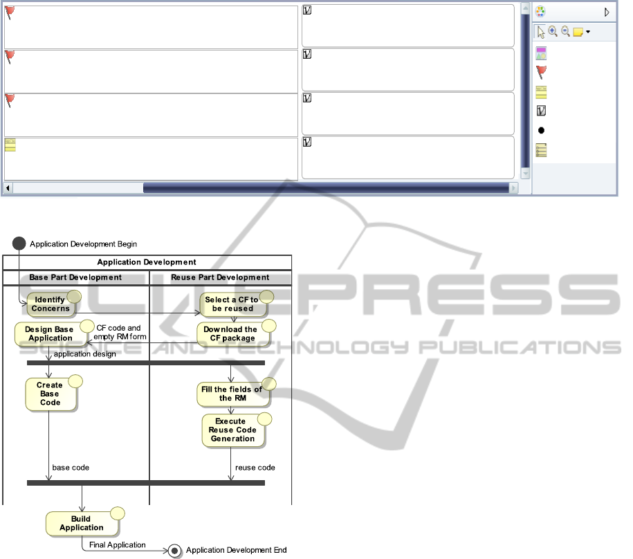
In this paper, we propose a new model named “Reuse
Model” (RM). We also created a graphical form to
represent the model as shown on Figure 1.
The RM should be provided by the framework de-
veloper in order to represent a reuse documentation
in a high level. Each CF available for reuse should
have its own RM. The idea is to release this model
along with the framework to support its reuse process.
Since the framework developer has good knowledge
regarding the framework, that person is able to docu-
ment how the reuse should be performed. The RM is
also used to document the information needed by the
framework in order to be coupled to the base code.
The RM is intended to improve the understand-
ability of the framework during reuse process. By an-
alyzing the model, an engineer reusing the framework
should be able to learn about the information needed
during the reuse process. This model also represents
the variabilities provided by a framework that must be
chosen by that engineer.
There are five possible elements in the presented
model: “Pointcuts”, “Type Extensions”, “Options”,
“Option Groups” and “Values”. The “PointCuts” rep-
resent join-points of the base application code that
should be affected by the crosscutting framework;
“Type Extensions” represent types found in the base
application that must extend or implement classes, as-
pects or interfaces found in the crosscutting frame-
work. “Option” and “Option Group” represent vari-
abilities provided by the CF that may be chosen by
the application engineer and “Value” represent any
other numeric or textual values that must be informed
while reusing the framework. For instance, to be
able to instantiate a persistence CF, the application
engineer must specify methods from base application
that should be executed after a database connection is
opened and before it is closed. It is also needed to
specify methods that represent data base transactions,
and the variabilities must be chosen, e.g., the driver
which should be used to connect to the database sys-
tem.
In order to instantiate the framework, the RM may
indicate the need of informing join-points of the base
code where crosscutting behavior would be applied,
as well as classes, interfaces or aspect names that
would be affected. Framework variabilities that must
be chosen during reuse process are also visible.
The RM is employed to support the reuse process
of a crosscutting framework. It is intended that the
reuse process can be completely executed by com-
pleting the form. Therefore, it should be used by the
application developer in order to reuse a framework.
When concluding the reuse process by completing the
model with the information needed by the framework,
the reuse code generation is possible. For example, on
Figure 1, there is an instantiation of the RM for a Per-
sistence CF (Camargo and Masiero, 2008). By pro-
cessing the model on a model to code transformation
process, the reuse code will be generated. This exam-
ple and the code generation are further explained in
the “Approach Usage Example” section.
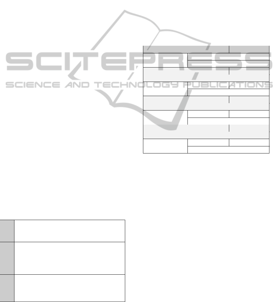
3.2 Development Process
A new reuse process is specified when considering the
model to support the reuse of Crosscutting Frame-
works. In order to explain the new process, there is
an activity diagram on Figure 2 which illustrates the
perspective of engineers reusing the framework.
The reuse process starts on the left side of the fig-
ure. The application being developed is composed
by the “Base” and “Reuse” modules. By analyzing
the application being developed (‘a’), the engineer
should be able to identify the concerns that would af-
fect the software, possibly by using an analysis di-
agram. By identifying these concerns, the engineer
has the opportunity to select crosscutting frameworks
at that moment and begin the reuse process since ear-
lier development phases (‘b’).
After selecting a crosscutting framework suited
for the current application development, that engineer
should download a CF package containing the cross-
cutting framework code and a reuse model (‘c’). This
model documents the information needed in order to
reuse the framework, however, at this point the fields
would be blank. Since the provided model is only a
template, these fields should be filled by the engineer
responsible for the base application.
The engineer should then design the base applica-
tion (‘d’), documenting the name of the units, meth-
ods and attributes found on the base application. It
is recommended to design the application after iden-
tifying the frameworks in order to develop a base ap-
plication design compatible to the framework. Since
this moment, the base application code must be cre-
ated by following the established design. At this same
time, by designing the application, names of base ele-
ments needed by the framework instantiation process
will become available, therefore, it would be already
possible to enter these names on the “Reuse Model
Form”. Then, the creation of the base and the reuse
code can be executed in parallel. In order to complete
the reuse form, the name of units, methods and at-
ICEIS2012-14thInternationalConferenceonEnterpriseInformationSystems
48
Pointcut
TypeExtension
Value
Option
OptionGroup
Group
Pointcut: Connection Closing
base.Customer.closing();
base.Customer.commitOrder();
base.Customer; base.Resource; base.Order;
"BasePassword"
"BaseOwner"
"127.0.0.1:5050/basename"
true
Specify if the persistent objects records should be updated automatic...
Provide the connection string necessary to connect to the database.
Provide the username needed to connect to the database.
Provide the password needed to connect to the database.
Palette
Value: Dirty Objects Controller
Pointcut: Connection Opening
Provide the names of methods which should execute only after a database connection is opened.
Provide the names of methods which execute before a database connection should be closed.
Pointcut: Transactional Methods
Provide the names of method which represent a database transaction.
TypeExtension: Persistent Objects
Provide the name of classes that represent objects that should be persisted.
base.Customer.closing();
Value: Database Connection String
Value: Database Username
Value: Database Password
Figure 1: Reuse Model Form.
a
b
d
c
e
f
g
h
Figure 2: Reuse Process Activity Diagram.
tributes found on the base application that are needed
by the framework must be supplied. After supply-
ing these names, which are the values needed by the
reuse portion, and concluding the reuse form, it will
be possible to execute a code generation. The code
generation is a model transformation to generate the
“Reuse Code” (‘g’) from a “Reuse Model”.
After completing the “Base Code” and the “Reuse
Code”, the application developer may chose between
adding a new concern (and extending the base appli-
cation) or finishing the process.
At that moment, the following modules are avail-
able: “Base Code”, the “Reuse Code” and the the se-
lected “Framework Code”. All of these are processed
to build the “Final Application” (‘h’), concluding the
process and the application is complete.
It is important to point that the tool being pre-
sented on this paper is part of a larger project we are
working in order to create a integrated development
environment for applications that reuse crosscutting
concerns. This environment also supports selection
of subsets of features of a framework and allows ap-
plication developers to download the framework in-
stance optimized to their needs. These details are not
described in this paper.
The Reuse Model contains information needed by
the framework being reused. By identifying that in-
formation during earlier development phases of the
base applications, it is easier to define it correctly in
a specific way which all information needed can be
easily extracted. Consequently, the base application
is not oblivious about the framework and its behav-
iors, however, the modules are completely isolated
and have no code dependency among them.
It is important to point that the Reuse Code itself
depends on the Base Code during the build process,
however,its definition can be made as soon as the base
application design is complete.
The advantage of modularizing the reuse code
with aspect oriented concepts removes the depen-
dence between the base application and the reuse
code. This allows repeating the code generation with-
out affecting the base code, which is not possible on
related works presented in the “Related Works” Sec-
tion. A new tool to support the process is presented in
the next section.
4 APPROACH USAGE EXAMPLE
In this work, a tool was implemented to support the
proposed process. The tool was developed using
Eclipse Modeling Framework (Eclipse Consortium,
2011). It is capable of presenting the proposed model
as a form and is also able to transform the model to
generate reuse code. For example, we employed the
AModel-basedApproachforReusingCrosscuttingFrameworks
49

tool to perform the reuse process on a Crosscutting
Framework that modularizes the persistence concern
(Camargo and Masiero, 2008).
The Reuse Model of the CF is shown in Figure 1.
The last line of each box is initially blank, and must be
filled by the application developer with details regard-
ing the base application. The pointcuts “Connection
Opening”, “Connection Closing” and “Transactional
Methods” are intended to capture specific join-points
of the base application, e.g. methods of the base ap-
plication that will be affected by the framework. The
first two represent, respectively, method that should
execute after a database connection is open or before
it is closed, whereas the last pointcut represents meth-
ods that encapsulate data transactions.
The “Persistent Objects” is a type extension defi-
nition, then, it may represent either a class or an in-
terface that should be extended or implemented by
a base class or interface. In this case, the applica-
tion engineer must supply names of classes (or their
super-types) which represent objects that should be
persisted on the database. The other elements repre-
sent framework variabilities that should be defined by
the application developer. For example, the form in
Figure 1 is completed with information of a base ap-
plication. There are three referenced “Persistent Ob-
jects”; their classes will receive methods and cross-
cutting behavior in order to implement the persistence
concern and persist their instances in a database.
There are four selected values on the right of the
figure. The first one is used to define if the objects
should be saved automatically upon modifying their
attributes, which can be performed by the “Dirty Ob-
jects Controller”. The second is employed to define
the connection string, finally, the other two inform the
connection user-name and password.
After completing the Reuse Model Form, it is pos-
sible to execute a code generator, which is a model
to code transformation tool capable of generating a
reuse code in AspectJ, illustrated on Figure 3, which
allows coupling the base application to the framework
in a separate module. The final software is the com-
position of base application code, reuse code for each
reused frameworkand the code of reused frameworks.
In the first aspect, the three pointcuts are imple-
mented by extending an abstract aspect of the frame-
work with information of the methods found in the
base application. In the second aspect, the type ex-
tension is implemented, then the classes “Customer”,
“Resource” and “Order” receive an interface of the
framework, which is used to apply crosscutting be-
havior. In the third aspect, the values are set by over-
riding methods of the framework. The interface “Se-
lectedManager” is implemented by classes which ex-
public aspect ConnectionCompositionReuse
extends ConnectionComposition {
public pointcut openConnection():
execution (* base.Customer.initial());
public pointcut closeConnection():
execution (* base.Customer.closing());
public pointcut transactional():
execution (* base.Customer.commitOrder());
}
public aspect OORelationalMappingReuse
extends OORelationalMapping {
declare parents: base.Customer
implements PersistentRoot;
declare parents: base.Resource
implements PersistentRoot;
declare parents: base.Order
implements PersistentRoot;
}
public aspect ConnectionVariabilities{
public String SelectedManager.setDSN(){
return "127.0.0.1:5050/basename";
}
public String SelectedManager.setUsername(){
return "BaseOwner";
}
public String SelectedManager.setPassword(){
return "BasePassword";
}
}
Figure 3: Reuse Code.
tend the selected database connection. However it is
not visible in this paper, due to size limitations.
5 EVALUATION
We conducted empirical studies in order to analyze
differences between using the reuse support tool and
using the conventional reuse technique, therefore, our
goal was to identify which technique takes less effort
to reuse a crosscutting framework. The planning of
this study was made considering the guidelines pro-
posed by (Wohlin et al., 2000).
5.1 Study Definition
The objective of the study is to compare the efforts
regarding the reuse of frameworks by using conven-
tional technique and the model based tool.
A Crosscutting Framework is considered in two
reuse techniques: The conventional reuse technique
and the model based tool that we created. The quanti-
tative focus is to compare the efforts needed to reuse
a framework with the model based reuse tool and
the conventional technique. The recorded timings are
considered to determine the effort. The qualitative fo-
cus is to determine which technique takes less effort
during reuse. The experiment was conducted from
the perspective of application engineers who intend to
reuse CFs. The study object is the “effort” to perform
a CF reuse process. The experiments were planned
to compare which technique takes less effort during
ICEIS2012-14thInternationalConferenceonEnterpriseInformationSystems
50
reuse. The subjects were required to reuse frame-
works using the different techniques. An information
system was created in order to gather the timings. We
added code to the reused applications to submit the
data to a server which combined all timings data into
a database with milliseconds precision. This submis-
sion was transparent to the participants.
This study was conducted with students of Com-
puter Science, in this section, they are referred as par-
ticipants. Sixteen participants took part on the experi-
ment, eight of these were undergraduate students and
the other eight were post graduate students. Every
participant had prior AspectJ experience and was re-
quired to reuse a CF for the persistence concern (Ca-
margo and Masiero, 2008), coupling it to a provided
application using either the model support tool or the
conventional ad-hoc technique.
The Table 1 contains our formulated hypotheses.
There are two variables shown on the table: “Tc” and
“Tm”. “Tc” represents the overall time to reuse the
framework using the conventional ad-hoc technique
while “Tm” represents the overall time to reuse the
framework using the model based tool. There are
three hypotheses shown on the table: “H0”, “Hp”
and “Hn”. The “H0” hypothesis is true when both
techniques are equivalent; then, the time spent using
the conventional technique minus the time spent us-
ing the model-based tool is approximately zero. The
“Hp” hypothesis is true when the conventional tech-
nique takes longer than the model-based tool; then,
the time spent to use the conventional technique mi-
nus the time of the model-based tool is positive. The
“Hn” hypothesis is true when the conventional tech-
nique takes longer than the model-based tool; then,
the time taken to use the conventional technique mi-
nus the time taken to use the model-based tool is neg-
ative. As these hypotheses consider different ranges
of a single resulting real value, then, they are mutu-
ally exclusive and exactly one of them is true.
Table 1: Hypotheses.
H0 There is no difference between using our tool and using
an ad-hoc reuse process in terms of productivity (time)
to successfully couple a CF with an application. Then,
the techniques are equivalent. Tc - Tm ≈ 0
Hp There is a positive difference between using our tool
and using an ad-hoc reuse process in terms of produc-
tivity (time) to successfully couple a CF with an ap-
plication. Then, the conventional technique takes more
time than the model based tool.
Tc - Tm > 0
Hn There is a negative difference between using our tool
and using an ad-hoc reuse process in terms of produc-
tivity (time) to successfully couple a CF with an appli-
cation. Then, the conventional technique takes less time
than the model based tool. Tc - Tm < 0
The dependent variables are those which we ana-
lyze in this work. For each study, we provide analysis
of the “time spent to complete the process”. The inde-
pendent variables are controlled and manipulated, for
example, “Base Application”, “Technique” and “Ex-
ecution Types”.
The participants were selected through non proba-
bilistic approach by convenience, i. e., the probability
of all population elements belong to the same sam-
ple is unknown. They were divided into two groups.
Each group was composed by four post graduate stu-
dents and four undergraduate students. Each group
was also balanced considering a characterization form
and their results from the pilot study. On Table 2,
there are the phases planned for the study.
Table 2: Study Design.
Phase Group 1 Group 2
Training
Reuse Techniques Training
Repair Shop
1
st
Reuse Conventional Models
Pilot Phase Hotel Application
2
nd
Reuse Models Conventional
Pilot Phase Library Application
1
st
Primary Conventional Models
Reuse Phase Deliveries Application
2
nd
Primary Models Conventional
Reuse Phase Flights Application
1
st
Secondary Conventional Models
Reuse Phase Medical Clinic Application
2
nd
Secondary Models Conventional
Reuse Phase Restaurant Application
Base applications were provided along with two
documents. The first document is a manual regarding
the current reuse technique, and the second document
is a list of details, which describes the classes, meth-
ods and values regarding the application to be coupled
which are needed when reusing the framework. The
applications had the same reuse complexity, then, in
order to reuse each application, the participants had to
specify four values, twelve methods and six classes.
Each phase row of the Table 2 is divided into the
name of the application and the technique employed
to reuse the framework.
5.2 Operation
At first, every student was introduced to the tool and
was taught how to reuse the crosscutting framework
using the tool and conventionally. During each phase,
the students were required to reuse the CF with a pro-
vided application. During the following phase, the
participants were required to use the opposite tech-
nique to reuse an equivalent application.
AModel-basedApproachforReusingCrosscuttingFrameworks
51
Initially, the participants signed the consent form
and then answered a characterization form, which had
questions regarding knowledge about AspectJ con-
structs, Eclipse IDE and Crosscutting Frameworks.
After concluding the characterization forms, par-
ticipants were trained on how to reuse the supplied CF
by using the model based reuse tool and then conven-
tionally. It is important to note that every participant
already had a basic experience with AspectJ and the
conventional reuse of crosscutting frameworks.
The pilot experiment was executed after the train-
ing. The participants were split into two groups con-
sidering the results of characterization forms. The pi-
lot experiment was intended to simulate the Primary
Study, except that the applications were different, but
equivalent. During the pilot experiment, the partic-
ipants were allowed to ask questions about any is-
sues they did not understand during the training. This
could affect the validity, then, the data from this ac-
tivity was only used to rebalance the groups.
During the Primary Study, the participants reused
other two applications starting with a different tech-
nique for each group. The Secondary Study was an-
other experiment with another two applications.
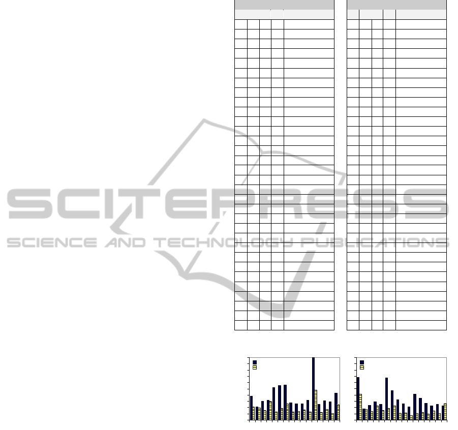
The recorded timings during the reuse processes
with both techniques during both study executions are
on Table 3. There are five columns in each of these ta-
bles, “G.” stands for the group of the participant dur-
ing the activity; “App.” stands for the application be-
ing reused; “T.” stands for the reuse technique which
is either “C” for conventional or “M” for model based
tool; “P.” column lists an identifying code of the par-
ticipants (students), whereas the least eight values are
allocated to post-graduate students and the rest are
undergraduate students; “Time” column lists the time
the participant spent to complete each reuse phase.
The information system was able to gather the
timings with milliseconds precision considering both
the server and clients system clocks. However, the
values presented in this paper only consider the server
time, then, the delay of transmission by the comput-
ers are not considered, which are believed to be in-
significant in this case, because preliminary calcula-
tions considering the client clocks did not change the
order of results.
5.3 Data Analysis and Interpretation
The timings data of Table 3 is also represented graphi-
cally in a bar graph, which is plotted on Figure 4. The
same code for each participant and the timings in sec-
onds are visible. The bars for conventional technique
and model tool use are paired for each participant, al-
lowing easier visualization.
Table 3: Reuse Process Timings.
Primary Study Secondary Study
G A T P Time G A T P Time
1 F M 15 04:19.952015 2 C M 10 02:59.467569
1 F M 13 04:58.604963 1 R M 13 03:56.785359
1 F M 8 05:18.346829 1 R M 15 04:23.629206
2 D M 11 05:24.249952 2 C M 11 04:25.196135
2 D M 5 05:31.653952 1 R M 8 04:33.954349
2 D M 9 05:45.484577 2 C M 9 04:41.254920
2 D M 3 06:16.392424 1 R M 12 05:05.524264
2 D M 10 06:45.968790 2 C M 3 05:45.333167
2 D M 14 07:05.858718 2 C M 14 05:57.009310
2 D M 6 07:39.300214 2 C M 5 06:31.365498
2 D M 2 08:02.570996 2 C M 2 06:59.967490
1 F M 1 08:38.698360 2 R C 2 07:18.927029
2 F C 2 08:42.389884 2 C M 6 07:45.403075
1 F M 16 10:18.809487 2 R C 10 08:56.765163
1 D C 13 10:25.359836 1 C C 16 09:20.284593
2 F C 9 10:51.761493 1 R M 7 09:23.574403
1 F M 7 10:52.183247 1 R M 4 09:25.089084
2 F C 10 10:52.495216 2 R C 14 09:27.112225
1 D C 8 11:39.151434 2 R C 3 09:55.736324
1 D C 15 12:03.519008 1 C C 15 10:25.475603
1 F M 4 12:17.693128 2 R C 5 10:37.460834
2 F C 3 12:26.993837 2 R C 9 10:49.014842
2 F C 14 12:49.585392 1 R M 16 10:56.743477
2 F C 11 13:04.272941 1 C C 13 11:04.485390
1 D C 4 13:16.470523 1 C C 4 12:06.690347
1 D C 1 15:47.376327 1 C C 8 13:38.014602
1 D C 16 18:02.259692 1 C C 12 14:37.197260
1 F M 12 20:03.920754 1 R M 1 17:09.073104
2 F C 5 21:32.272442 2 R C 11 17:11.980052
2 F C 6 23:10.727760 1 C C 7 19:35.816561
1 D C 7 23:20.991158 2 R C 6 28:02.391335
1 D C 12 41:29.414342 1 C C 1 28:18.301114
Primary Secondary
1
2
3
4
5
6
7
8
9
10
11
12
13
14
15
16
0
250
500
750
1000
1250
1500
1750
2000
2250
2500
Conv.
Model
1
2
3
4
5
6
7
8
9
10
11
12
13
14
15
16
0
250
500
750
1000
1250
1500
1750
2000
2250
2500
Conv.
Model
Figure 4: Reuse Process Timings Bars Graph.
An important information found on the Primary
Study is that there is not a single participant that could
reuse the framework faster by using the conventional
process than by using the reuse tool. The Secondary
Study has provided similar results, only a single par-
ticipant was able to be faster by using the conven-
tional technique.
On Table 4 there are average timings and their
proportions. By dividing the average time spent dur-
ing the conventional process by the average time
spent during model-based process, the result implies
that the conventional technique took approximately
97.64% longer than the model based tool.
ICEIS2012-14thInternationalConferenceonEnterpriseInformationSystems
52
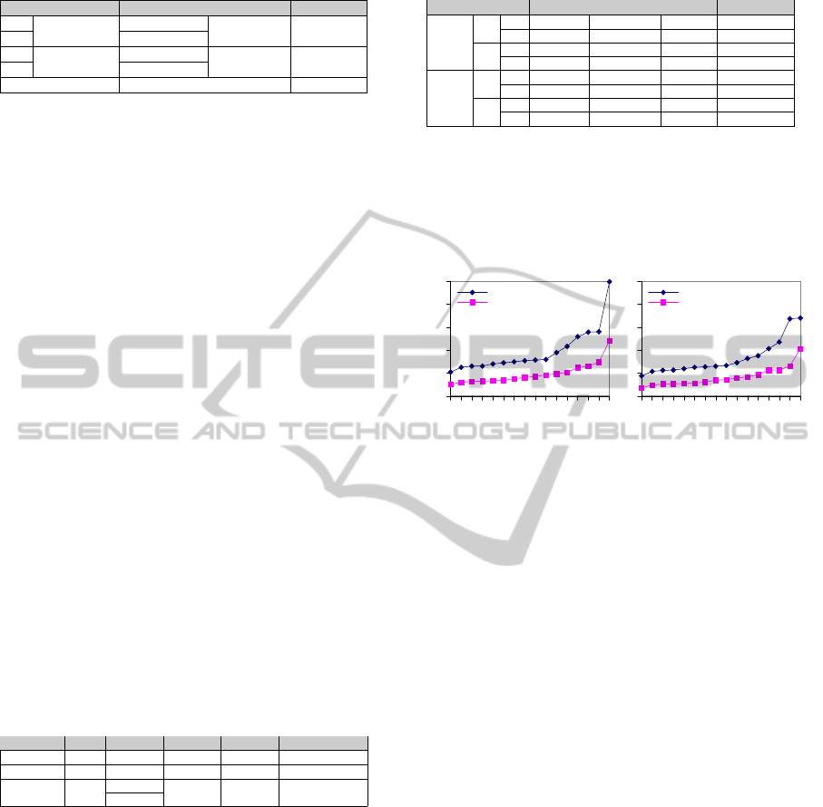
Table 4: Average Timings.
G. Tech. Avg. Avg.(tech.) Percents
1
Conventional
18:18.613745
32:25.698286 66.4026%
2 14:07.084541
1
Model Based
09:46.65831
16:24.454048 33.5974%
2 06:37.795738
Total 48:50.152334 100.0000%
5.4 Hypothesis Testing
We applied Paired T-Tests for each of the presented
studies and another T-Test after removing eight out-
liers. The seconds spent were processed using the
statistic computation environment“R” (Free Software
Foundation, 2011). The results of the T-Tests are
shown on Table 5. The first column contains the
type of T-Test, the second indicates the source of the
data, the “Means” column indicate the resultant mean,
which is the mean of the differences for an paired T-
Test and one mean for each set for the other T-Test,
which represent the conventionaland the model based
tool means, respectively. The “d.t.” column stands for
the degree of freedom; “t” and “p” are variables con-
sidered in the hypothesis testing.
The Paired T-Test is used to compare the the dif-
ferences between two samples related to each partici-
pant, in this case, the time difference of every partici-
pant is considered individually,and then, the means of
the differences are calculated. The other T-Test is not
paired, the means are calculated for the entire group,
because a participant may be an outlier in a specific
technique, which breaks the pairs. It is referred as
two-sided because the two sets have the same number
of elements, since the same number of outliers were
removed from each group.
Table 5: T-Test Results.
T-Test Data Means d.f. t p
Paired Real 488.4596 15 5.841634 3.243855·10
−05
Paired Spare 417.8927 15 5.285366 9.156136·10
−05
Two-Sided Both
771.4236
43.70626 6.977408
1.276575·10
−08
409.4295
A “Chi-squared test” was applied in order to de-
tect the outliers that were removed when calculating
the last T-Test, which is referred as “Two-sided”. The
results of the “Chi-squared test” are found on Table 6.
The ‘M’ in the techniques column indicates the use
of our tool while ‘C’ indicates the conventional tech-
nique, the group column indicates the number of the
group; the ‘X
2
’ indicates the result of an comparison
to the variance of the complete set and the position
column indicates their position on the set, i.e., highest
or lowest. The “outlier” column shows the timings in
seconds that were considered abnormal.
In order to achieve better visualization of the out-
liers, we also provide line graphs. there are two line
Table 6: Chi-squared test for outlier detection.
Study T. G. X
2
p position outlier
Real
C
1 5.104305 0.02386654 highest 2489.414342
2 2.930583 0.08691612 highest 1390.72776
M
1 4.091151 0.04310829 highest 1203.920754
2 2.228028 0.1355267 highest 482.570996
Spare
C
1 4.552248 0.03287556 highest 1698.301114
2 5.013908 0.02514448 highest 1682.391335
M
1 3.917559 0.04778423 highest 1029.073104
2 2.943313 0.08623369 lowest 179.467569
graphs in Figure 5 which may be also used to visu-
alize the dispersion of the timing records. In these
plots, the timings for each technique are ordered inde-
pendently, therefore, the participant numbers in these
plots are not related to their identification codes.
Real Spare
1
2
3
4
5
6
7
8
9
10
11
12
13
14
15
16
0
500
1000
1500
2000
2500
Conv.
Model
1
2
3
4
5
6
7
8
9
10
11
12
13
14
15
16
0
500
1000
1500
2000
2500
Conv.
Model
Figure 5: Reuse Process Timings Lines Graph.
According to the analysis from Table 5, since all
p-values are less than the margin of error (0.01%),
which corresponds to the established significance
level of 99.99%, then, statistically, we can reject the
“H0” hypothesis that states the techniques are equiv-
alent. Since every t-value is positive, we can accept
the “Hp” hypothesis, which considers that the con-
ventional technique takes more time than our tool.
5.5 Threats to Validity
The varied participant knowledge that could affect the
collected data. To mitigate this threat, we divided the
participants in two balanced groups considering the
experience level and rebalanced the groups consider-
ing the preliminary results.
Students often tend to think they are being eval-
uated by experiment, which could affect the results.
In order to mitigate this, we explained to the students
that no one was being evaluated and their participa-
tion was considered anonymous.
Different computers and installations could affect
the recorded timings. However, the different groups
used equivalent computers in equal numbers and the
participants were not allowed to change their ma-
chines during the same activity.
The participants already knew the researchers and
knew that the model based tool was supposed to ease
the reuse process. In order to avoid impartiality, we
enforced that the participants had to keep a steady
pace during the whole study.
AModel-basedApproachforReusingCrosscuttingFrameworks
53

It is possible that the reuse exercises are not ac-
curate for every reuse of a crosscutting framework
for real world applications. Only a single crosscut-
ting framework was considered and the base applica-
tions had the same complexity. To mitigate this threat,
the exercises were designed considering applications
based on the real world.
We also applied three T-Tests to statistically ana-
lyze the experiment data, which improves reliability.
6 RELATED WORKS
The approach proposed by (Cechticky et al., 2003) al-
lows object-oriented application framework reuse by
using a tool called OBS Instantiation Environment.
That tool supports graphical models do define the set-
tings of the expected application to be generated. The
model to code transformation generates a new appli-
cation that reuses the framework.
The proposal found in this paper differs from their
approach on the following topics: 1) their approach is
restricted to frameworks known during the develop-
ment of the tool; 2) it does not use aspect orientation;
3) the reuse process is applied on application frame-
works, which are used to create new applications.
Another approach was proposed by (Oliveira
et al., 2011; Oliveira et al., 2007). Their approach
can be applied to a greater number of object oriented
frameworks. After the framework development, the
framework developer may use the approach to ease
the reuse by writing the cookbook in a formal lan-
guage known as Reuse Definition Language (RDL)
which also can be used to generate the source code.
This process allows to select the variabilities and re-
sources during reuse, as long as the framework engi-
neer specifies the RDL code correctly.
These approaches were created to support the
reuse during the final development stages. There-
fore, the approach proposed in this paper differs
from others by the supporting earlier development
phases. This allows the application engineer to initi-
ate the reuse process since the analysis phase while
developing an application compatible to the reused
frameworks. Although the approach proposed by
(Cechticky et al., 2003) is specific for only one frame-
work, its can be employed since the design phase.
The other related approach can be employed in a
higher number of frameworks, however it is used in
a lower abstraction level, and does not support the de-
sign phase. Other difference is the generation of AOP
code, which improves code modularization.
7 CONCLUSIONS
Considering the advantages of reducing the time
needed to develop an information system, in this pa-
per, a model based process was presented, which
raises abstraction levels of CF reuse. It serves as a
graphical view that replaces textual cookbooks and
is used to perform the reuse in a model driven ap-
proach. From our proposed model-based approach, a
new reuse process was delineated, which allows engi-
neers to start the reuse since earlier software develop-
ment phases and reduce the time to reuse a CF.
Also, a new tool was developed to support the
reuse process, which allows visualization of the form
and is capable of transforming the models in order to
generate the reuse code. With this, application devel-
opers do not need to worry about reuse coding issues
nor how the framework was implemented, allowing to
focus on the reuse requirements in a higher abstrac-
tion level.
We have conducted experiments that indicate that
our tool has advantages on reducing the time to reuse
a CF. With our tool, it is possible to develop infor-
mation systems that reuse crosscutting frameworks in
less time than by reusing the frameworks convention-
ally, which gives advantages to companies that rely
on these systems.
It is also important to point that our tool is part of
a project to develop an integrated development envi-
ronment for frameworks, which currently supports CF
feature subset selection and a CF repository service.
However, it was not yet analyzed if the tool brings
advantages when maintaining an existing software
nor if the tool may lead to more or less errors during
development, which encourages us to conduct more
experiments. We also need to evaluate how to deal
with coupling multiple crosscutting frameworks to a
single base application. Despite this functionality al-
ready being supported, some frameworks may con-
flict with each other and lead to unwanted results.
The code generated is based on AspectJ and it was
not evaluated if it supports every CF without modifi-
cations. Although not stated, we have also worked on
selecting subsets of features of the framework.
ACKNOWLEDGEMENTS
Thiago Gottardi would like to thank FAPESP (Pro-
cess 2011/04064-8) and CNPq (Processes 132996/
2010-3 and 560241/2010-0) for funding. Also, this
paper was created inside a Universal Project granted
by CNPq (Process Number 483106/2009-7).
ICEIS2012-14thInternationalConferenceonEnterpriseInformationSystems
54

REFERENCES
Bynens, M., Landuyt, D., Truyen, E., and Joosen, W.
(2010). Towards reusable aspects: The mismatch
problem. In Workshop on Aspect, Components and
Patterns for Infrastructure Software (ACP4IS’10),
pages 17–20.
Camargo, V. and Masiero, P. (2005). Frameworks orien-
tados a aspectos. In Anais Do 19 Simpsio Brasileiro
De Engenharia De Software (SBES’2005), Uberlndia-
MG, Brasil, Outubro.
Camargo, V. V. and Masiero, P. C. (2008). A pattern to de-
sign crosscutting frameworks. In Proceedings of the
2008 ACM symposium on Applied computing, SAC
’08, pages 759–764, New York, NY, USA. ACM.
Cechticky, V., Chevalley, P., Pasetti, A., and Schaufelberger,
W. (2003). A generative approach to framework in-
stantiation. In Proceedings of the 2nd international
conference on Generative programming and compo-
nent engineering, GPCE ’03, pages 267–286, New
York, NY, USA. Springer-Verlag New York, Inc.
Cunha, C., Sobral, J., and Monteiro, M. (2006). Reusable
aspect-oriented implementations of concurrency pat-
terns and mechanisms. In Aspect-Oriented Software
Development Conference (AOSD’06), Bonn, Ger-
many.
Eclipse Consortium (2011). Graphical Modeling
Framework, version 1.5.0. http://www.eclipse.org/
modeling/gmp/.
Fayad, M. and Schmidt, D. C. (1997). Object-oriented ap-
plication frameworks. Commun. ACM, 40:32–38.
France, R. and Rumpe, B. (2007). Model-driven devel-
opment of complex software: A research roadmap.
In 2007 Future of Software Engineering, FOSE ’07,
pages 37–54, Washington, DC, USA. IEEE Computer
Society.
Huang, M., Wang, C., and Zhang, L. (2004). Towards a
reusable and generic aspect library. In Workshop of the
Aspect Oriented Software Development Conference at
AOSDSEC’04, Lancaster, UK.
Kiczales, G., Hilsdale, E., Hugunin, J., Kersten, M., Palm,
J., and Griswold, W. G. (2001). An overview of
AspectJ. pages 327–353. Springer-Verlag.
Kiczales, G., Lamping, J., Mendhekar, A., Maeda, C.,
Lopes, C., marc Loingtier, J., and Irwin, J. (1997).
Aspect-oriented programming. In ECOOP. Springer-
Verlag.
Kulesza, U., Alves, E., Garcia, R., Lucena, C. J. P. D., and
Borba, P. (2006). Improving extensibility of object-
oriented frameworks with aspect-oriented program-
ming. In Proc. of the 9th Intl Conf. on Software Reuse
(ICSR’06), pages 231–245.
Lazanha, R., Oliveira, A., Penteado, R., Ramos, R., Pas-
tor, O., and Camargo, V. (2010). Uma arquitetura de
referncia baseada em papis para frameworks transver-
sais de persistncia: Uma anlise quantitativa. In XXXVI
Clei – Conferncia Latino-Americana de Informtica,
Assuno, Paraguay.
Mortensen, M. and Ghosh, S. (2006). Creating pluggable
and reusable non-functional aspects in AspectC++.
In Proceedings of the Fifth AOSD Workshop on As-
pects, Components, and Patterns for Infrastructure
Software.
Free Software Foundation, Inc. (2011). R. http://www.r-
project.org/.
Oliveira, T. C., Alencar, P., and Cowan, D. (2011).
Reusetool-an extensible tool support for object-
oriented framework reuse. J. Syst. Softw.,
84(12):2234–2252.
Oliveira, T. C., Alencar, P. S. C., de Lucena, C. J. P.,
and Cowan, D. D. (2007). RDL: A language for
framework instantiation representation. J. Syst. Softw.,
80:1902–1929.
Pastor, O. and Molina, J. C. (2007). Model-Driven Architec-
ture in Practice: A Software Production Environment
Based on Conceptual Modeling. Springer-Verlag New
York, Secaucus, NJ, USA.
Sakenou, D., Mehner, K., Herrmann, S., and Sudhof, H.
(2006). Patterns for re-usable aspects in object teams.
In Net Object Days, Erfurt.
Schmidt, D. C. (2006). Model-driven engineering. IEEE
Computer, 39(2).
Shah, V. and Hill, V. (2004). An aspect-oriented security
framework: Lessons learned. In Proceedings of AOS-
DSEC’04 (AOSD Technology for Application-Level
Security). Workshop of the Aspect Oriented Software
Development Conference, Lancaster, UK.
Soares, S., Laureano, E., and Borba, P. (2006). Distribution
and persistence as aspects. Software: Practice and
Experience, 33(7):711–759.
Soudarajan, N. and Khatchadourian, R. (2009). Specify-
ing reusable aspects. In Asian Workshop on Aspect-
Oriented and Modular Software Development (AOA-
sia’09).
Wohlin, C., Runeson, P., H¨ost, M., Ohlsson, M. C., Regnell,
B., and Wessl´en, A. (2000). Experimentation in soft-
ware engineering: an introduction. Kluwer Academic
Publishers, Norwell, MA, USA.
Zanon, I., Camargo, V. V., and Penteado, R. A. D. (2010).
Reestructuring an application framework with a per-
sistence crosscutting framework. INFOCOMP, 1:9–
16.
AModel-basedApproachforReusingCrosscuttingFrameworks
55
