
Automated Design of Reconfigurable Manufacturing Systems
A Framework based on a Genetic Algorithm and Discrete System Simulation
J. Padayachee and G. Bright
Discipline of Mechanical Engineering, University of KwaZulu-Natal, King George V Avn, Durban, South Africa
Keywords: Reconfigurable Manufacturing Systems, Discrete System Simulation, Genetic Algorithms, Manufacturing
System Design.
Abstract: The concept of Reconfigurable Manufacturing Systems (RMSs) was formulated due to the global necessity
for production systems that are able to economically evolve according to changes in markets and products.
Technologies and design methods are under development to enable RMSs to exhibit transformable system
layouts, reconfigurable processes, cells and machines. Existing manufacturing design systems do not
encapsulate concepts of reconfigurability in design mechanisms to obtain optimal RMS configurations. This
paper presents a framework for a resource allocation and shop floor design system within the context of
RMSs. The framework focuses on the automated generation of shop floor configurations for systems with
high product variety and shared resources. The DEVS, (Discrete Event System Specification), formalism is
used to model reconfigurable equipment and simulate manufacturing processes. The “design engine” in the
proposed framework, implements a genetic algorithm for the assembly, evaluation and optimisation of
candidate shop floor configurations and their corresponding DEVS models.
1 INTRODUCTION
The concept of Reconfigurable Manufacturing was
first proposed and formalised by researchers at the
University of Michigan in the late 1990s. A
definition of Reconfigurable Manufacturing Systems
as follows (Koren et al., 1999): “ A Reconfigurable
Manufacturing System (RMS) is designed at the
outset for rapid change in structure, as well as in
hardware and software components, in order to
quickly adjust production capacity and functionality
within a part family in response to sudden changes
in market or regulatory requirements.”
The RMS concept has evolved out of the
inadequacy of previous manufacturing paradigms in
addressing the global manufacturing challenges of:
economically managing the rapid rate of product
development, frequent changes in parts and
products, fluctuations in product demand and mix
and changes in product and process technology
(Malhotra et al., 2009). In order to address these
challenges RMSs are envisioned to exhibit
transformable system layouts, reconfigurable
processes, cells and machines. Reconfigurability in
RMSs is also specified to be achieved by the use of
modular mechanical hardware and control elements
that can be rapidly integrated into Reconfigurable
Machine Tools (RMTs), material handling systems,
quality control systems and product assembly
mechanisms to achieve new levels of system
functionality (Moon and Kota, 2002, Mehrabi et al.,
2000).
The nature of RMSs presents the necessity to
quickly alter factory floor configurations when the
system can no longer meet the demands of the
production schedule. The generation of RMS
configurations that facilitate alterations to its
machines is essential to maintaining system
productivity under changing production demands.
Existing manufacturing design systems do not
encapsulate concepts of reconfigurability in design
mechanism to obtain optimal RMS configurations.
This paper presents a framework for an automated
resource allocation and shop floor design system for
RMSs.
2 RELEVANT LITRATURE
A method for the design of a RMS was presented by
(Koren and Shpitalni, 2010). The method extends to
the design of a RMS configuration for a single part
153
Padayachee J. and Bright G..
Automated Design of Reconfigurable Manufacturing Systems - A Framework based on a Genetic Algorithm and Discrete System Simulation.
DOI: 10.5220/0004009001530158
In Proceedings of the 9th International Conference on Informatics in Control, Automation and Robotics (ICINCO-2012), pages 153-158
ISBN: 978-989-8565-21-1
Copyright
c
2012 SCITEPRESS (Science and Technology Publications, Lda.)
family. The first stage in the method is a calculation
of the number of machines required to complete an
operation. The number of machines N, may be
arranged in a variety of different configurations. The
minimum number of stages in a configuration is
limited to the number of machine setups required to
produce the part family. Koren’s method requires
the manual population of a space of potential
configurations. The selection of an optimal
configuration then proceeds by eliminating those
configurations that cannot meet the required
production rate. Consideration is also given to
system throughput with machine reliability less than
100%, investment cost, scalability and floor space.
Koren and Shpitalni presented a manual method of
enumerating and evaluating candidate RMS
configurations. The number of configurations that N
machines may assume, grows factorially with the
number N. This method therefore requires
substantial amounts of time and human effort to
enumerate and evaluate different configurations.
The use of the Analytic Hierarchy Process,
(AHP), was proposed by (Abdi, 2005) for the design
of a suitable RMS. The AHP was originally
developed by Thomas L. Saaty and the details of this
algorithm may be found in (Saaty, 2008). The AHP
requires a set of design alternatives and a set of
design criteria as inputs to the algorithm. Abdi listed
reconfigurability, cost, quality and reliability as the
design objectives. The implementation presented by
Abdi required the manual enumeration of possible
RMS design configurations. This method, like
(Koren and Shpitalni, 2010), is unappealing due to
the time required to enumerate and rank various
configurations.
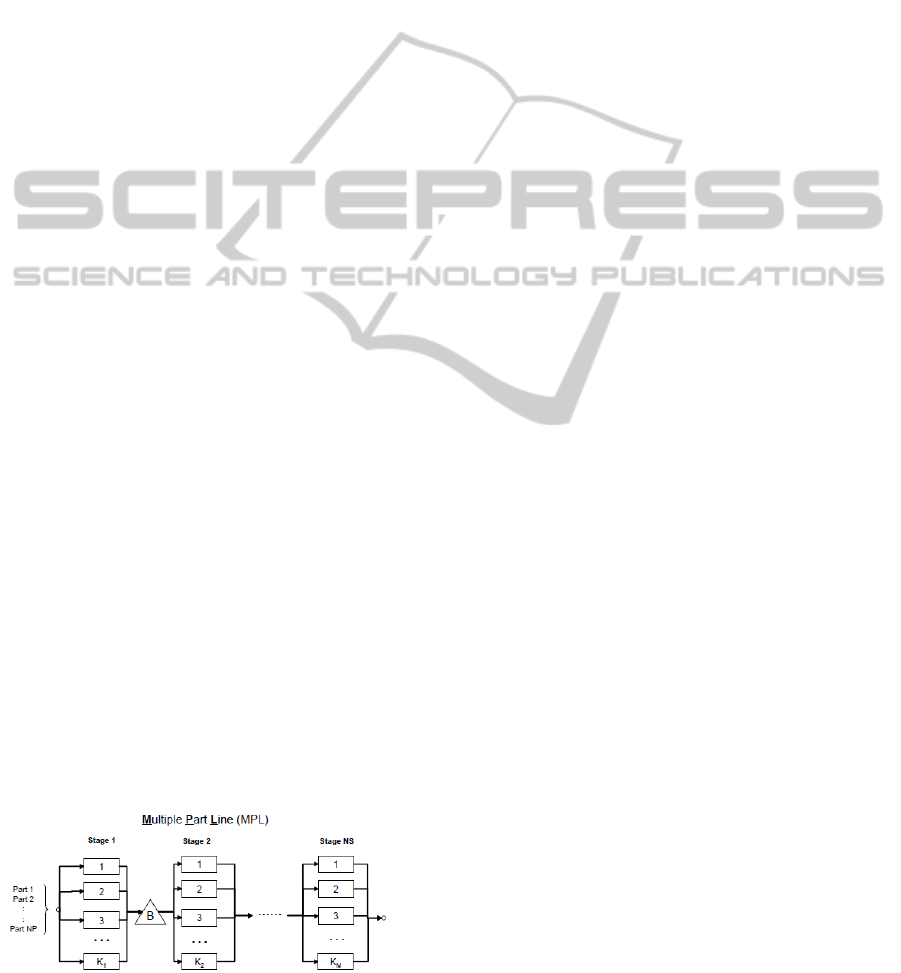
The use of a Genetic Algorithm to design a
Multiple Part Line (MPL) for RMSs was proposed
by (Tang et al., 2003). Tang defined a MPL as a line
that consists of several serial stages with a finite size
buffer between every two stages. Each stage consists
of identical machines in parallel that perform the
same set of tasks. The problem formulation
restricted the MPL to the production of a given part
family. It was assumed that the number of stages in
the MPL is predetermined by the designer and each
Figure 1: Illustration of a Parallel MPL (Tang et al., 2003).
part visits every stage in the MPL. The objective of
the optimisation was therefore, to allocate machines
to the various stages of the MPL from a given
library of available machines. Limitations in this GA
implementation include the specification that the
RMS layout assumed a form as depicted in Figure 1.
3 PARALLEL DEVS
SIMULATION
The use of computer simulation for the design of
RMSs has been largely overlooked. This research
pursues the use of simulation for manufacturing
system design within an automated framework. The
Parallel Discrete Event System (Parallel DEVS)
specification has been chosen as the formalism for
the simulator. DEVS was selected because the
formalism is hybrid, i.e capable of modelling both
discrete event and discrete time systems. The
formalism is also modular and hierarchical thus
making it suitable for creating manufacturing system
models that can be generated and modified
automatically during the execution of a genetic
algorithm. The Parallel DEVS variation of the
original DEVS formalism was introduced (Chow
and Zeigler, 1994). A Parallel DEVS model consists
of Atomic Models that are networked to form
coupled models. An Atomic DEVS model M is an 8-
tuple defined by:
Where:
X: is a set of input events;
Y: is a set of output events;
S: is a set of sequential states;
δ
ext
: Q × X
b
→ S, is an external transition function;
where Q = {(s,te)|s
S, 0≤te≤ta(s)} is the total state
set of M and te is the time elapsed since the last the
last event;
δ
int
: S → S, an internal transition function;
δ
con
: S × X
b
→ S, is the confluent transition function;
λ: S → Y
b
, is an output function;
ta: S → Real, is the time advance function.
Atomic DEVS models have been used to model the
elementary components of a manufacturing system
such as buffers, machines, assembly stations, human
labourers, robots and material transport systems.
Atomic models are stored in a manufacturing
resource/ equipment library:
Atomic models from this library are selected to
create candidate design solutions for a
ICINCO 2012 - 9th International Conference on Informatics in Control, Automation and Robotics
154

reconfigurable manufacturing system. A candidate
design solution is a network of atomic models,
which, as a whole is a discrete system model of a
manufacturing system. The structure of a coupled
model according to the Parallel DEVS formalism is:
Where:
X: is a set of input events;
Y: is a set of output events;
D: is a set if component names {i};
{M
i
}: is a set of atomic components, {M
i
}
{I
i
}: I
i
is the set of other atomic models, by name,
that influence the
i
th
atomic model
{Z
i,j
}:
is the of set of input and output couplings
The structured population of the 6-tuple coupled
model to create viable candidate manufacturing
system configurations requires the use of a
reconfigurable process plan used in conjunction with
a selection and organisation strategy.
4 RECONFIGURABLE PROCESS
PLANS
A Reconfigurable Process Plan, unlike a traditional
process plan, is a set of all possible mappings
between a part feature and the variety of machines
that are available to create that feature. The most
elementary building block of a reconfigurable
process plan is a process descriptor. A process
descriptor P
i
,
j,k
is used to represent information
pertaining to the creation of feature k on a part, using
machine i in configuration (setup) j. Recall that the
machines available to RMSs are reconfigurable, this
is discussed in (Moon and Kota, 2002, Padayachee
et al., 2009). The description P
i,j,k
is a 3 – tuple
defined by:
where:
tm: is the time for part feature k to be completed on
machine i in configuration j;
q: is the feature quality confidence on machine i in
configuration j (0< q < 1);
c: is the cost of machining feature k on machine i in
configuration j.
The process descriptor therefore assists
automated resource allocation by presenting a
mapping between a part feature and a machine, as
well as the information that may be used to evaluate
the optimality of the relationship.
RMSs will contain multiple types of
reconfigurable machinery capable of providing
similar processing operations. Therefore the creation
of a feature on a part may be achieved by a variety
of machines with different setups; the number of
possibilities may be encapsulated in a set:
The set of feature may then be grouped to represent
an entire part; this may be written as an ordered set,
where the precedence of feature creation is
according to a prescribed sequence:
Parts may also be grouped into part families, and
part families into product platforms (a family of
assemblies) as described above. The set
PLATFORM
o
is a set of all possible process plans
and corresponding resource allocations for a product
platform.
5 CANDIDATE RMS
CONFIGURATIONS
Candidate RMS configurations are generated by first
selecting a process descriptor for each part feature
F
k
. Once a process descriptor has been selected for
the creation of a part feature, the corresponding
machine is selected from the set LIB. The allocation
(final mapping) of machines to part features is stored
in a set called MAP. One MAP exists per part family.
This process is performed repeatedly until all
features on all parts to be manufactured have had a
manufacturing resource allocated to them. A flow
chart of the procedure is illustrated in Figure 2.
Multiple part features, on parts from the same
family, may be created by the same type of machine
(possibly with the same setup). Such features are
grouped into Operational Groups (OG). The
machines on which an OG is executed are grouped
for further analysis:
OG
u
={<P
ijk
,M
i
>,… }
In an OG, the feature number k and the setup
(configuration) number j of the process descriptors
change but the machine number i stays the same.
The elements of an OG are further divided to form
smaller Operational Clusters (OC), i.e. .
Formation of operational clusters depends on
features requiring the same type of setup on the
same type of machine. Because RMSs allow
dynamic changes to machines and setups,
Automated Design of Reconfigurable Manufacturing Systems - A Framework based on a Genetic Algorithm and Discrete
System Simulation
155
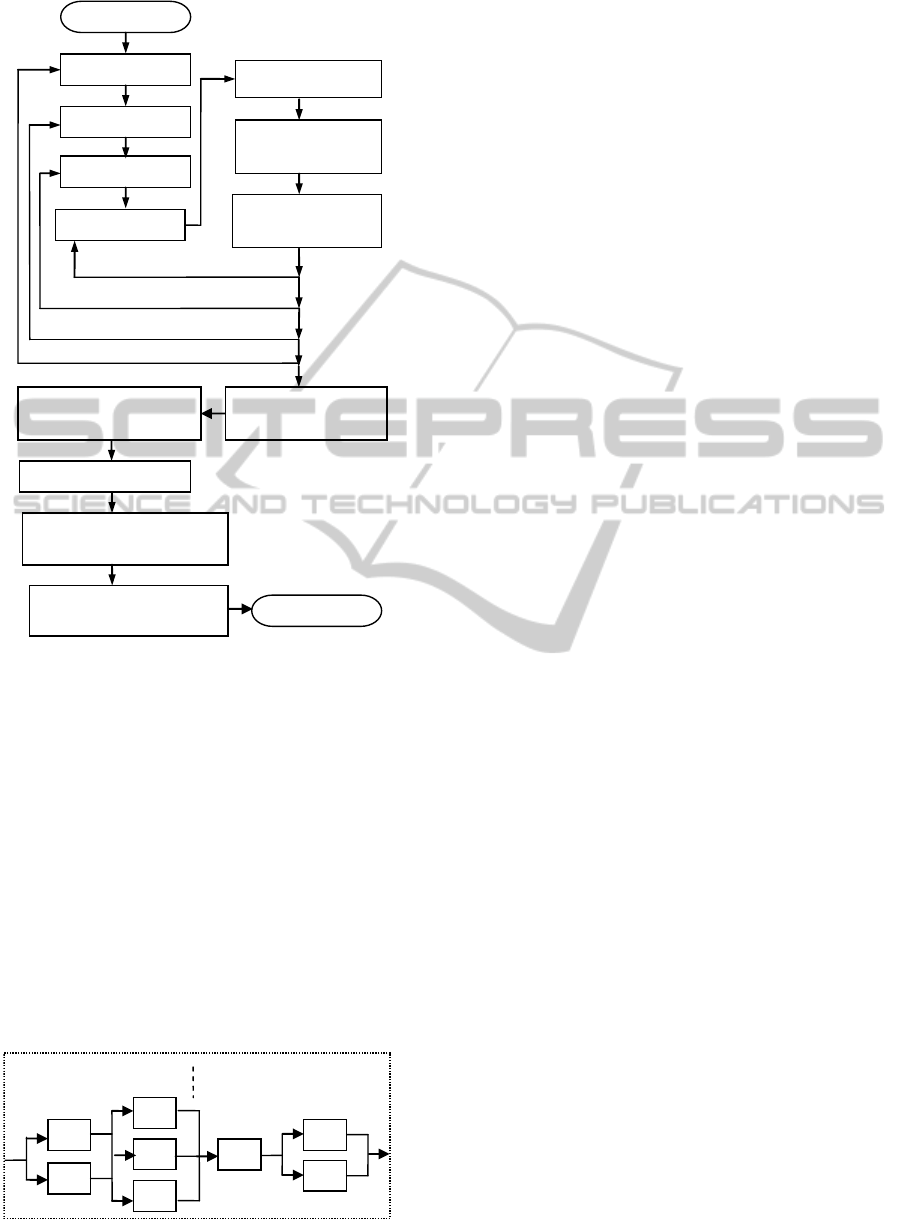
Figure 2: Process for Generating Candidate RMSs.
operational clusters may also be allowed on a
machine where the required setup change is minimal
between parts.
Machines in an OC are then duplicated until the set
of machines forms a STAGE able to provide the
required daily production rate. Multiple stages are
then spatially arranged according to a prescribed
sequence of operation:
SC
v
= {STAGE
1
, …STAGE
u
}
The Spatial Configuration of stages (SC) will
correspond to one part family and its block of
manufacturing lines. The block of manufacturing
lines that are described by SC may be translated in to
facility layout diagrams as illustrated by Figure 3.
Figure 3: Spatial Configuration of a Block of Lines.
Multiple blocks of manufacturing lines such as those
illustrated in Figure 3 will be placed on the factory
floor for each part family in the system. All lines
will eventually lead to assembly stations. Facility
layout for assembly lines constitutes future work and
is not considered in this paper.
6 OPTIMISATION STRATEGIES
6.1 Feature – Machine Mapping
The design of a RMS may be optimised at multiple
levels using various modifications. The first
modification that can be made to the design is
changing the mapping between a part feature and the
machine used to make it. This will require the
complete redesign of the entire block of lines in
which that feature is created. Changing the machines
used to create a feature would usually require
swapping machines between other blocks of lines,
unless the library of manufacturing equipment has
excess machines of an appropriate type available
(practically unlikely). A single modification of this
type therefore has the ability to cause great changes
in a candidate solution. This type of modification is
therefore unsuitable as an optimisation mechanism.
A rule, algorithm (e.g. the Analytic Hierarchical
Process) or heuristic should be used for selecting the
most appropriate machine to create a feature at the
outset and once a mapping has been established it
should not be altered as an optimisation mechanism.
6.2 Operational Clusters, Stages and
Blocks
The division of operational groups into clusters, the
formation of stages from clusters and the
arrangement of stages into blocks of manufacturing
lines, is sizeable combinatorial optimisation
problem. The operational group will need to be
divided across multiple stages such that:
the production rate under a static
production schedule is optimal,
flow is balanced between different stages,
the production rate is least diminished
when reconfigurations are required as per a
dynamically changing production schedule.
Finding an optimal configuration for a block of
lines, and considering that a manufacturing system
would consist of multiple blocks; the colossal task of
finding an optimal configuration for all blocks
would be a process that is best automated by a
SelectFEATURE
Select P
ijk
Select Corresponding
M
i
from LIB
Add mapping to set
MAP={<P
ijk
,M
i
>,…}
Select FAMILY
Select PART
Select PLATFORM
for F
1
…
k
for PART
1
…
m
for FAMILY
1
…
n
for PLATFORM
1
…
o
Start
Candidate RMS
Spatial Configuration SC
Select Mat Handling and Buffers
M
i
from LIB, add to SC
Create OG from MAP
÷ OG to form smaller OC
Add all M
i
from SC to DN,
Populate< X, Y, D,{I
i
}, {Z
i,j
}>
Duplicate M
i
in each stage
according to req Prod Rate
OC1.1
OC1.2
OC2.2
OC2.2
OC2.1
OC1.2
OC1.2
OC1.2
OG 1
OG 2
Stage 1
Stage 5
ICINCO 2012 - 9th International Conference on Informatics in Control, Automation and Robotics
156
suitable algorithm.
7 OPTIMISATION ROUTINE
7.1 Genetic Encoding
As a first initiative in the development of an
automated design system for RMSs, the authors
propose that the optimisation of the design be
executed within the structure of a Genetic
Algorithm. Encoding for an operational group and
its corresponding operational clusters is a binary
matrix of links between machines and features:
Each row of the matrix represents machines from 1-
n and each column, the features that could be created
on those machines from 1-k. Blocks of operational
group lines are stored in the ordered set BLOCK.
7.2 Genetic Operations
Standard genetic operations are gene mutation and
crossover. For gene mutation pair wise “bit flipping”
of elements in an operational group matrix is
performed. The operation is pair wise because once
a feature has been assigned a new operational cluster
within a group, its assignment to another cluster
must be deactivated.
For genetic crossover to be performed in a
meaningful way, while still maintaining the integrity
of a candidate solution, this operation has been
restricted to swopping of ‘OG’ elements from one
BLOCK set with those from another BLOCK for the
same part family.
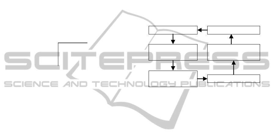
7.3 Execution of Algorithm
The execution of the Genetic Algorithm begins with
the creation of an initial set of candidate solutions as
per the routine outlined in Section 5. When an initial
set of candidate solutions have been created the
encoding of the solution must be represented in two
formats; a format that may be used to construct
DEVS models and a genetic encoding. DEVS
coupled models are assembled and simulated to
produce results that may be analysed and used for
fitness evaluations. The use of simulation as part of
the optimisation procedure is essential for examining
the effect that reconfiguration will have on the
production rate for different OG and BLOCK
configurations. Simulation will also help identify
zones of buffer over flow, buffer starvation and
unacceptable machine idle times and idle
frequencies. Data analysis of simulation results
therefore has the ability to be used to exactly exploit
problematic areas by means of genetic operators.
However, a balance between solution exploitation
and exploration must be observed to prevent
premature convergence of solutions onto local
minima.
Figure 4: Execution Cycle for Genetic Algorithm.
A performance metric for a block of lines would
be the ratio of reconfiguration sensitivity to cost.
Reconfiguration sensitivity is an indicator of the
effect of reconfigurations on the productivity of a
block of lines. A suitable formulation and method of
determining reconfiguration sensitivity constitutes
future work.
Once candidates have been selected for genetic
operations and these operations have been applied to
create modified solutions; the genetic encoding must
be translated into new DEVS models for the next
iterative cycle. This cycle is shown in Figure 4, and
continues until no significant improvement is
demonstrated between successive iterations.
8 CONCLUSIONS
The framework presented in this paper requires
significant software development for the full
automation of the design system. A major
component of future work will include the software
development of the automated RMS configuration
generator and DEVS model assembler. The software
implementation will be built on the modeling
formalism presented in Section 3, the concept of
reconfigurable process plans presented in Section 4
and the routine presented in Section 5.
The exploration of appropriate Genetic
Candidate RMSs
DEVS Simulation
Data Analysis &
Fitness Evaluation
Genetic Operations
Assemble DEVS
coupled models
Translate Genetic
encoding to DEVS
Automated Design of Reconfigurable Manufacturing Systems - A Framework based on a Genetic Algorithm and Discrete
System Simulation
157

Algorithm configurations will also be conducted.
This will include research into advanced
performance metrics, improves genetic
recombination techniques and offspring selection
strategies. This research is necessary to ensure the
implementation of an algorithm that does not
converge prematurely on to sub-optimal RMS
configurations.
ACKNOWLEDGEMENTS
The authors would like to gratefully thank the
Technology Innovation agency, (TIA), together with
the Department of Science and Technology- South
Africa for the provision of project funding and
resources during this research.
REFERENCES
Abdi, M. R. 2005. Selection of a Layout Configuration for
Reconfigurable Manufacturing Systems using the
AHP. 8th International Symposium on the Analytic
Hierarchy Process Multi-criteria Decision Making.
Honolulu, Hawaii, USA.
Chow, A. C. H. & Zeigler, B. P. 1994. Parallel DEVS: A
Parallel Hierarchical, Modular Modeling Formalism.
In: Proceedings of 1994 Winter Simulation
Conference, Lake Buena Vista, FL, USA.
Koren, Y., Heisel, U., Jovane, F., Moriwaki, T.,
Pritschow, G., Ulsoy, G. & Van Brussel, H. 1999.
Reconfigurable Manufacturing Systems. Annals of the
CIRP, 48, 527-540.
Koren, Y. & Shpitalni, M. 2010. Design of Reconfigurable
Manufacturing Systems. Journal of Manufacturing
Systems, 29, 130-141.
Malhotra, V., Raj, T. & Arora, A. 2009. Reconfigurable
manufacturing system: an overview. International
Journal of Machine Intelligence, 1, 38-46.
Mehrabi, M. G., Ulsoy, A. G. & Koren, Y. 2000.
Reconfigurable Manufacturing System and Their
Enabling Technologies. International Journal of
Manufacturing Technology and Management, 1, 113 -
130.
Moon, Y.-M. & Kota, S. 2002. Design of Reconfigurable
Machine Tools. Journal of Manufacturing Science and
Engineering, 124, 480 - 483.
Padayachee, J., Bright, G. & Masekamela, I. 2009.
Modular Reconfigurable Machine Tools: Design,
Control and Evaluation. South African Journal of
Industrial Engineering, 20, 127-143.
Saaty, T. L. 2008. Decision Making with the Analytic
Hierarchy Process. International Jourrnal of Services
Sciences, 1, 83-98.
Tang, L., Yip-Hoi, D. M., Wang, W. & Koren, Y. 2003.
Concurrent Line-Balancing, Equipment Selection and
Throughput Analysis for Multi-Part Optimal Line
Design. CIRP 2nd International Conference on
Reconfigurable Manufacturing. Ann Arbor, MI, USA.
ICINCO 2012 - 9th International Conference on Informatics in Control, Automation and Robotics
158
