
Modeling and Simulation of Humanoid Robot Spine Vertebra
M. Souissi, V. Hugel and P. Blazevic
Université de Versailles Saint Quentin en Yvelines, Versailles, Île-de-France, France
Keywords:
ROMEO Robot, Simulation, Vertebral Column, Mechanical Structure, Kinematics.
Abstract:
In this paper, a parallel mechanism is proposed for the design of humanoid vertebra. This mechanism is
inspired by a flight simulator system, and has been adapted and optimized to enable pitch and roll motion
of a humanoid trunk at reduced energy cost. The system consists of a bottom platform and a top platform
connected by two articulated arms and a vertical central rod. A 3D model of the system has been elaborated
for simulation and design.
1 INTRODUCTION
Robots are expected to live among humans to assist
them in their daily tasks. Current humanoid robots
are not fully suitable for working in our daily environ-
ment. They can do a few limited tasks compared with
what a human can do. Walking humanoids robots
equipped with joints in the trunk are listed in table 1 in
increasing order of spine DOF number starting from
pelvis. All of them feature a yaw joint in the trunk.
The yaw joint is particularly useful for taking larger
strides. It can also be used to compensate for yaw
moment between feet and ground. It allows the robot
to increase the working volume of its upper body for
manipulation. Existing humanoids that have a yaw
joint in the trunk are Asimo presented by (Sakagami
et al, 2002), KHR2, Hubo in (Kim, 2005), Johnnie
analysed by (Loffler et al, 2005), and Lola (Lohmeier
et al, 2006). An additional pitch joint in the trunk
extends the skills of the robot. The pitch joint is help-
ful for the robot to sit down on a chair. Examples of
robots that can sit down are the series of REEM-A/B
presented in (Tellez, 2008). This robot is manufac-
tured by Pal Technology Robotics. Humanoids with
a pitch joint in the trunk can also stand up from lying
position. The HRP2 robot demonstrated its capacity
to lie on the ground and to stand up again using its
pitch joint in the trunk (Kaneko, 2008). Roll joints
can be added to enhance locomotion capacities. That
is the case of the last generation of Wabian robots de-
veloped by Waseda University in Japan (Ogura et al,
2006). Wabian II features two additional roll joints –
one in the middle of the pelvis and the other one at
the end of the trunk kinematic chain – that were in-
troduced to implement new locomotion skills. This
robot is capable of stretching the knee during walk
when the supporting leg comes below the hip. Pitch
and roll joints also increase the working space of the
upper body and they can be used to bend the trunk
forward and /or sideways to grasp something or to re-
sist some perturbation at shoulder level. The DOF in
Table 1: Walking humanoid robots with DOF in the trunk.
DOF type of DOF Prototypes
1 yaw KHR2, Hubo,
Johnnie,
Asimo
2 yaw +pitch HRP-2-3-4,
Reem A/B
4 roll + yaw + pitch + roll Wabian II
the trunk are therefore task-dependent. It is interest-
ing for humanoids to have a vertebral column to deal
with both movement and manipulation skills.
The contribution of this paper consists of adapt-
ing an existing parallel mechanism of flight simulator,
found in thses of (Emilie, 2004), to the design of a
pitch-roll vertebra joint, taking into account the spec-
ifications of forward, backward and left/right side-
ways bending amplitudes given for a humanoid robot.
The objective of the study is to optimize the different
length ratios of the mechanism in order to have a re-
duced torque required for the bending motions.
Section II deals with the description of the paral-
lel mechanism. Section III presents simulation and
results. Section IV is devoted to conclusion and per-
spectives.
415
Souissi M., Hugel V. and Blazevic P..
Modeling and Simulation of Humanoid Robot Spine Vertebra.
DOI: 10.5220/0004013904150418
In Proceedings of the 9th International Conference on Informatics in Control, Automation and Robotics (ICINCO-2012), pages 415-418
ISBN: 978-989-8565-22-8
Copyright
c
2012 SCITEPRESS (Science and Technology Publications, Lda.)
2 DESCRIPTION OF
MECHANISM
This work deals with the adaptation of an existing par-
allel mechanism to a prototype of vertebra that could
be implemented on humanoid robots. The parallel
mechanism consists of 2 platforms – one bottom plat-
form CA
3
B
3
and one top platform OA
1
B
1
, that are
linked by a central vertical rod CO and two arms ar-
ranged at 90[deg] in the initial position (Fig. 1). The
central rod CO is fixed and always remains vertical. It
joins the top platform through a Universal joint whose
drive is responsible for roll and pitch motion of the
top platform. The arm A
1
A
2
A
3
is planar and is com-
posed of two segments, two revolute joints at A
2
and
A
3
, and one Universal joint at A
1
. This is the planar
arm. Figure 2 shows the parallel mechanism.
k
O
A
1
B
2
B
3
B
1
A
2
A
3
C
j
i
h
1
h
2
ℓ
1
ℓ
2
ℓ
3
ℓ
4
d
1
d
2
d
3
d
4
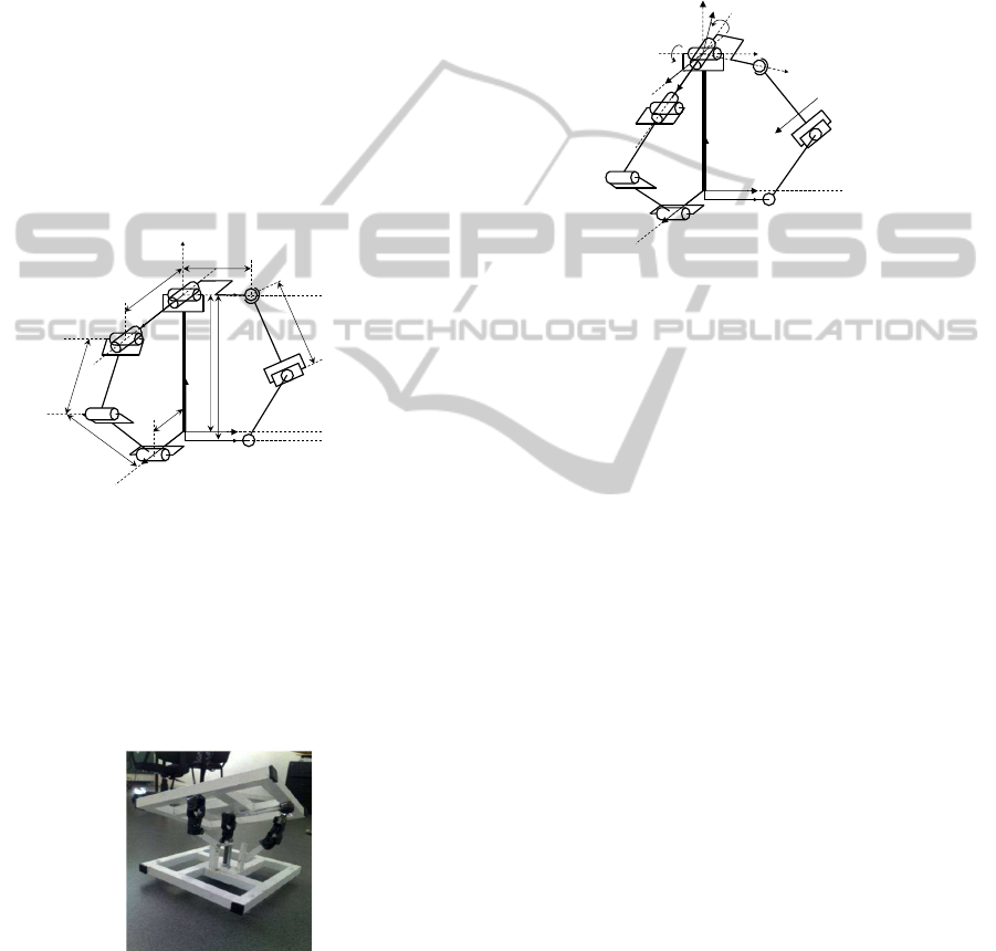
Figure 1: Perspective view of parallel mechanism in initial
position. The central rod is fixed and rigid. It is attached to
the top platform by a Universal joint at O. The mechanism
is actuated by two revolute joints, each of them is located
at the bottom of each arm. The two arms are arranged at
90 [deg]. The arm A
1
A
2
A
3
is planar and remains in the (xz)
remains in this plane. It is composed of two revolute joints
and one U-joint. The other arm B
1
B
2
B
3
is initially in the
(yz) plane, and does not remain in this plane if the top plat-
form rolls.
Figure 2: Parallel mechanism.
The arm B
1
B
2
B
3
also includes two segments, one
revolute joint at B
3
, one Universal joint at B
2
and one
ball joint at the attachment locus B
1
with the top plat-
form. This arm is 3D. The bottom platform is linked
to coordinate frame R
0
, centered at C with axes i, j
and k.
The top platform rotates about O and is linked to co-
ordinate frame R
0
, frame centered at O whose axes are
i
0
, j
0
and k
0
(Fig. 3).
The top platform can be pitched about fixed axis j
by angle θ
10
, and rolled about axis i
0
by angle θ
21
.
The two active joints are the revolute joints at A
3
and B
3
. The associated rotation angles are denoted by
α and β.
k
O
A
1
B
2
B
3
B
1
A
2
A
3
C
j
i
θ
10
θ
21
i'
i
j'
j
k
k'
u
Figure 3: Perspective view of parallel mechanism after pitch
and roll rotations.
3 SIMULATION AND RESULTS
3.1 Setup
Two configurations of mechanism are under study
here. Figure 4 shows both configurations. The first
configuration is rotated 90[deg] and the second one
is rotated 135[deg] with respect to the configuration
of the mechanism depicted on figure 3. This section
aims to compare both configurations and shows that
the second one is better than the first one in matter of
torque consumption.
In the first configuration, the height between the
top platform and the bottom platform in the parallel
mechanism is set to 0.1[m]. The length d
1
must be
less than half the width of the trunk, which is 0.24[m].
The length `
1
must be less than half the depth of the
trunk, which is 0.16[m]. These values result from a
space constraint because the vertebrae will be placed
in the lumbar part of the humanoid trunk. A sphere
with a mass M is placed above at the center of the
mechanism to simulate the upper part of a humanoid
robot. The two arms are perpendicular and they do
not have the same dimensions. The mass M is set to
15[kg]. The distance of the sphere center to the top
platform is set to 0.1[m].Table 2 presents the lengths
of the first configuration.
In the second configuration d
1
and l
1
are the same
as in the first configuration. A sphere with a mass M
is placed above the mechanism to simulate the upper
part of a humanoid robot. M is not placed at the center
ICINCO2012-9thInternationalConferenceonInformaticsinControl,AutomationandRobotics
416
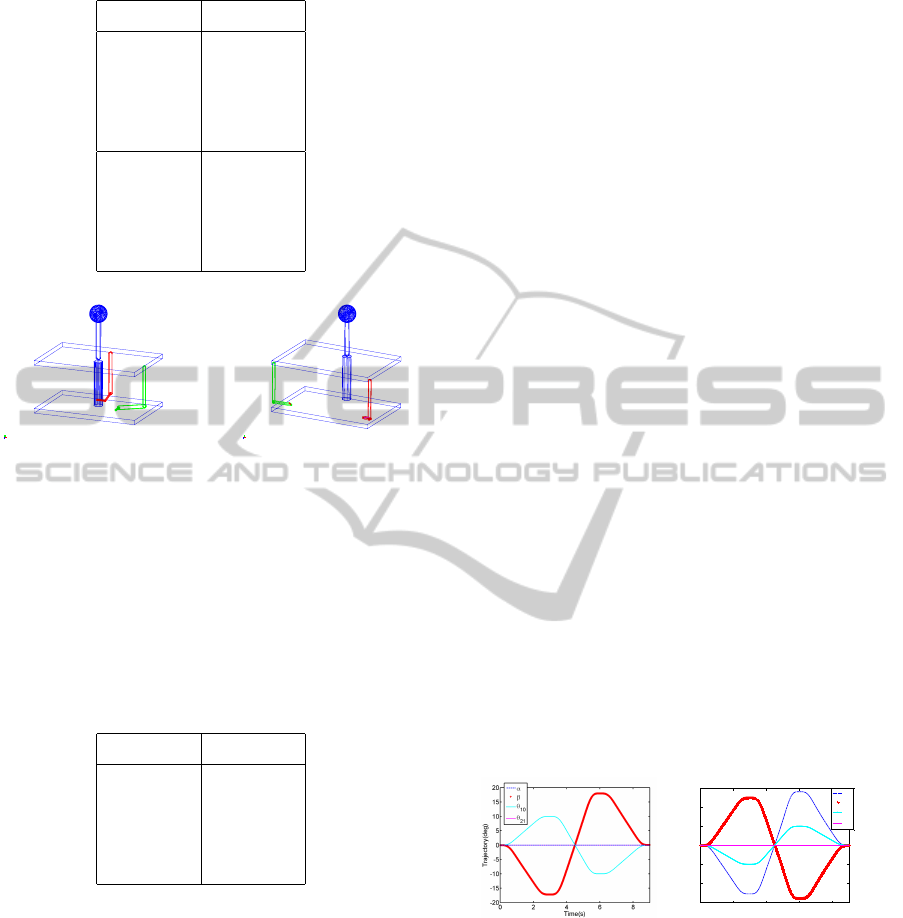
Table 2: Parameters of the first configuration.
Parameter length [m]
d
1
0.07
d
2
0.09
d
3
0.0316
d
4
0.04
l
1
0.11
l
2
0.09
l
3
0.06082
l
4
0.05
proto1
x
z
y
MODEL_1
x
z
y
Figure 4: The first and second configuration of parallel
mechanism.
of the prototype like in the first configuration, but at a
distance of 0.030[m] to the front of the trunk. This en-
ables to put the projection of the center of mass more
inside the center of the support polygon delimited by
the robot’s footprints . Both arms are symmetric and
perpendicular. Table 3 presents the lengths of the sec-
ond configuration.
Table 3: Parameters of the second configuration.
Parameter length [m]
d
1
= l
1
0.17
d
2
= l
2
0.09
d
3
= l
3
0.0443
d
4
= l
4
0.16
Both configurations are compared in matter of
torque magnitude delivered by the two active joints
for two kinds of motions to be executed by the top
platform.
The first motion is obtained by giving the angu-
lar inputs for the pitch/roll joint of the top platform,
namely θ
10
and θ
21
. This motion is named pitch in-
clination. The platform is bent 10[deg] forward, then
10[deg] backward. The angles for the joint motors,
namely α and β are calculated thanks to the inverse
geometric model.
In the second motion pitch and roll joint angles
are combined to have a bent circular motion of the
spherical mass. First, the mass is pitched by 10[deg].
Then it executes a complete circular motion about the
vertical. The trajectory for this circular motion uses
spherical notation and precession angles (θ, φ) as in-
puts. These inputs are then converted into θ
10
and θ
21
to execute the motion.
Trajectory planning is designed with Matlab-
SIMULINK, which is used to control the ADAMS
model. To control the inclination of the spherical
mass in Adams PID controllers were used for the mo-
tors.
The parameters (d
i
,l
i
) of the mechanism
were optimized by testing several configurations
(Souissi,2012) to check which one was best in matter
of torque magnitude and space occupancy. Each arm
was tested separately by fixing the other one. For the
first configuration we concluded that the motor axes
should be located at half-way between the center and
the related external edge of the top platform. For
the second configuration the motor axes should be
located more externally. In addition the upper part of
each arm must be longer than its lower part in both
configurations. This enables to optimize the lever
arm.
3.2 Torque Comparison between the
First Configuration and Second
Configuration
Figure 5 shows the trajectories of platform pitch and
roll angles θ
10
and θ
21
and the related motor angles α
and β in the case of pitch inclination motion. Figure
7 is related to the circular motion. The left-hand part
of each figure is related to first configuration and the
right-hand part to the second configuration.
0 2 4 6 8
-30
-20
-10
0
10
20
30
Time(s)
Trajectory(deg)
α
β
θ
10
θ
21
Figure 5: Angle trajectories θ
10
and θ
21
of platform and the
related motor angles α and β for the pitch inclination mo-
tion. Left: First configuration. Right: second configuration.
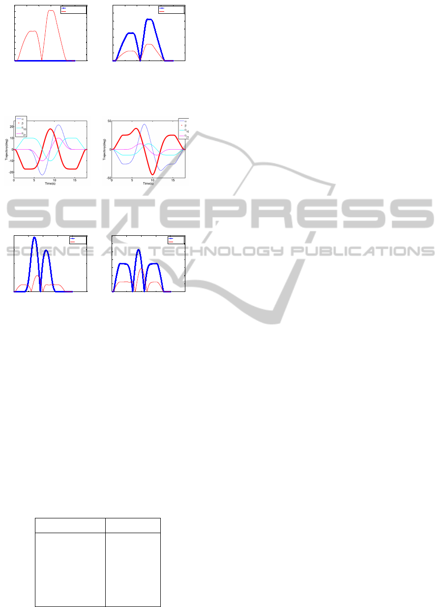
Figure 6 shows the torques of each arm’s motor
joint in both configurations for the pitch inclination
motion. Figure 8 shows the torques of each arm’s mo-
tor joint in both configurations for the circular motion.
Regarding pitch motion and circular motion the
second mechanism allows a torque reduction of more
than 50% with respect to the first.
ModelingandSimulationofHumanoidRobotSpineVertebra
417
0 2 4 6 8 10 12
0
0.05
0.1
0.15
0.2
0.25
0.3
0.35
0.4
Time(s)
Torque(NM)
first-config
second-config
0 2 4 6 8 10 12
0
0.2
0.4
0.6
0.8
1
1.2
1.4
Time(s)
Torque(NM)
first-config
second-config
Figure 6: Active torques in the first and second configura-
tion for the pitch inclination motion. Left: 2D arm. Right:
3D arm.
Figure 7: Angle trajectories θ
10
and θ
21
of platform and the
related motor angles α and β for the circular motion. Left:
first configuration. Right: second configuration.
0 5 10 15 20 25
0
0.5
1
1.5
2
Time(s)
Trajectory(NM)
first
second
0 5 10 15 20 25
0
0.2
0.4
0.6
0.8
1
1.2
1.4
Time(s)
Torque(NM)
first
second
Figure 8: Active torques in the first and second configura-
tions for the circular motion. Left: 2D arm. Right: 3D arm.
3.3 Mechanical Design of the
Mechanism
The second mechanism was simulated with Solid-
works. All joints come from the HPC company. For
both active joints electric motors are used. Torque
versus speed was plotted for both movements of the
top platform. The variation of torque with speed al-
lows to select the motors that best suit our needs.
We use Maxon motors, because these actuators are
lightweight and one of them meets our requirements:
the RE25G. The caracteristics of the motors are given
in table 4.
Table 4: Parameters of the motor.
Characteristic Value
Supply voltage 12V
Rated current 1.2 A
No load speed 202 r / min
Load speed 156 r / min
Rated torque 0.49 Nm
4 CONCLUSIONS AND
PERSPECTIVES
A new vertebra mechanism for a humanoid robot ver-
tebral column has been proposed. It is based on a par-
allel architecture driven by two active arms equipped
with one rotary actuator each. Inverse kinematic
equations have been formulated. A 3D model has
been elaborated with Adams and Solidworks and sim-
ulated for checking the operation feasibility and de-
sign sizes. Simulation results show that the proposed
column system can reproduce some of the human
spine mouvments.
REFERENCES
Emilie (2004) “Analyse d’un mécanisme de simulation de
vol sphérique et son contrôle en temps reel”, Faculté
des sciences et de génie universitaire, Laval, Québec,
2004. In French.
Kaneko et al. (2004). “Humanoid robot HRP-2”, Proceed-
ings of the IEEE International Conference on Rob.
and Aut., 1083–1090, 2004.
Kim et al. (2005). “System Design and Dynamic Walking
of Humanoid Robot KHR-2”, IEEE/RSJ International
Conference on Robotics and Automation, 1431–1436,
2005.
Loffler et al. (2003). “Sensor and Control Design of a Dy-
namically Stable Biped Robot”, Proc. IEEE Int. Con-
ference on Robotics and Automation, 484–490, 2003.
Lohmeier et al. (2006). “Modular joint design for perfor-
mance enhanced humanoid robot lola”, Proceedings
of the IEEE International Conference on Robotics and
Automation, 88–93, 2006.
Ogura et al. (2006). “Development of a New Humanoid
Robot WABIAN-2”, Proceedings of the 2006 IEEE
International Conference on Robotics and Automa-
tion, 76–81, 2006.
Tellez et al. (2008). “Reem-B: an autonomous lightweight
human-size humanoid robot”, 8th IEEE-RAS Interna-
tional Conference on Humanoids. 462–468, 2008.
Sakagami et al. (2002). “The intelligent ASIMO: system
overview and integration”, IEEE/RSJ Int. Conference
on Intelligent Robot and System, vol. 3, 2478–2483,
2002.
Souissi et al. (2012). “Design Optimisation of Parallel Joint
Mechanism for Humanoid Spine” in The 16th IEEE
Mediterranenan Electrotechnical Conference2012
ICINCO2012-9thInternationalConferenceonInformaticsinControl,AutomationandRobotics
418
