
Simulative Model and Multicriteria Optimization of Truss Beam
in Super-Large Columns at High Temperature
Yanzhen Liu, Hong Gao and Jinsheng Sun
School of Chemical Engineering and Technology, Tianjin University, No. 92 Wei Jin Road, Tianjin 300072, P.R. China
Keywords: Truss Beam, Multicriteria Optimization, Super-Large Column, Finite Element Analysis, Side Beam.
Abstract: With the increasingly enlarged process scale and the consequent requirement for large equipment, such as
column, trusses ever widely applied in civil and building engineering have been introduced in petroleum
chemical industry these years. Under this circumstance, truss structure optimization emerges as a study
focus to balance safety, durability and economy. In this paper, an optimization example is introduced of a
main truss beam system, namely centre, and its side beams in super-large column at high temperature. The
main truss beam is optimized on three counts, that is, cross-section shape of the chord members, structure
height and the pairs of the web members, while side beams are optimized by compromising among
workability, stress, stiffness and weight.
1 INTRODUCTION
With the rapid development of global petrochemical
industry, super-large column application becomes an
inevitable trend of choices in unites of this area, so
how to improve the performance (mass-transfer
efficiency, stability, operation safety, etc.) of the
super-large column is becoming a hot topic (Wang,
2011).
Supporting beams as one of the important parts
in super-large column have great impacts on mass-
transfer efficiency and operation safety. Trusses ever
widely applied in civil and building engineering are
now tend to be used as supporting beam instead of
traditional beams, such as I beams and channel
beams, in super-large column. Moreover, optimum
truss beam systems are believed to have following
properties (Pascal, 2011): (1) enough strength to
support separation or reaction apparatus, such as
packings and trays, and possible less deformation to
reduce structural deflection which will cause uneven
or unsteady liquid flow within these apparatuses;
(2) optimal shapes to lessen vortexes which
aggravate the harmful gas phase turbulent move; (3)
lower pressure drop; (4) material-saving, and
workability; That is, to further increase the operation
efficiency in large-scale chemical production, a
comprehensive optimization will be inevitable. So
how to optimize truss beam structure applied in
petrochemical industry is an indispensable work that
should be taken into account.
Many investigations about optimization of truss
beams based on mathematics or FEA has been done
to provide the most efficient design of a given
structure that complies with all applicable strength,
stiffness and light weight requirements (William and
Yong, 2004). But most works aim to optimize the
structure size or to adjust the relations between the
design variables and state variables to reduce the
cost in ambient temperature on the basis of ensuring
the enough strength and less deformation.
In this case, the truss operates in super-large
column, with a smaller elastic modulus of the
material at field high temperature, which results in
larger deformation and puts forward higher demands
to optimization methods. So three criteria of
simulative optimization by ANSYS have been
provided to work out the least weight of the truss
beams in the following work, that is, the cross-
section shape combinations of chord members and
web members (Kočvara, 2002), height and the pairs
of the web members, which finally lessen the weight
with better stiffness. Besides, factories normally
tend to apply too safe truss beams as side beams.
However, side beams simplified and simulated in
this paper demonstrates that available I beams
perform well to meet the current field applications.
177
Liu Y., Gao H. and Sun J..
Simulative Model and Multicriteria Optimization of Truss Beam in Super-Large Columns at High Temperature.
DOI: 10.5220/0004016001770181
In Proceedings of the 2nd International Conference on Simulation and Modeling Methodologies, Technologies and Applications (SIMULTECH-2012),
pages 177-181
ISBN: 978-989-8565-20-4
Copyright
c
2012 SCITEPRESS (Science and Technology Publications, Lda.)
2 MODEL AND OPTIMIZATION
2.1 Structure Description
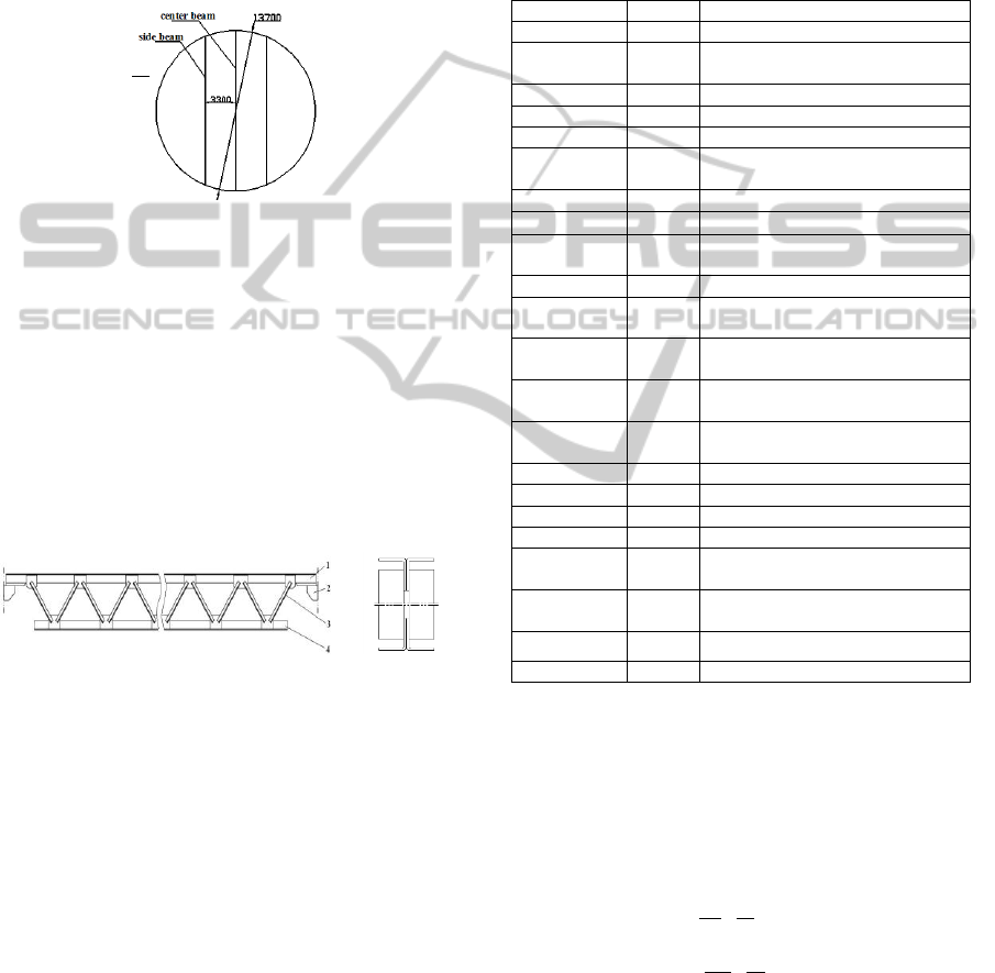
Truss beam in a vacuum column with diameter of
13700mm is called centre beam, and the side beams
are in the both sides of the centre beam with a
distance of 3300mm. The visual position is showed
as figure 1.
Figure 1: Distribution of beams.
The truss beam is made up of three parts, namely
top and bottom chord members as well as web
members (figure 2). The top chord member is fixed
on the inner surface of the column by supporting
brackets at both ends of the beam. This truss uses
double-web member. At both sides of the structure,
web members are weld to the top and bottom of
chord members, by attaching on the joints board.
This structure can improve the integral stability and
stiffness. The initial top and bottom chords consist
of two angle steels that are attached by welding.
Figure 2 structure of the truss.
1-top chord member; 2-stopporting bracket; 3-ten pairs of web
members; 4-bottom chord members
The truss is operated under 400℃ in the strong
corrosive environment. The material selected for it
in this condition is 316L with the prosperities of
strong heat-resistant and corrosion-resistant. Its
mechanical property parameters and initial sizes
under operating conditions are collected in the table
1 (Wang, 2008).
2.2 Finite Element Simulative Model
The universal finite element software ANSYS has a
rich unit library with a powerful function of before
and after processing. According to the prosperities
of each unit, the structure of the truss and the load
on it, when calculated, are simplified as follows:
(1) Unites attributes. Truss is a kind of plane
structure, which is mainly bending deformation
when being loaded. So when modeled, chord
members can be built with the attribute of beam 188,
which is an more appropriate unit in this linear and
large angle rotation or nonlinear big strain project, as
well as web members.
Table 1: Initial parameters.
parameter
value
remarks
dist/mm
670
nodal distance
height/mm
700
height between top and bottom
nodes
h/mm
900
initial whole height of truss beam
l
g
/mm
13440
length of truss
q
top
/N/mm
2
20.698
top linear load
q
bottom
/N/mm
2
1.612
bottom linear load
E/N/mm
2
1.69e5
elastic modulus
0.31
Poisson's ratio
den/Kg/mm
3
7.85e-
6
density
n
10
Initial pairs of the web members
bottomw1/m
m
450
width of chord members
bottomw2/m
m
200
height of chord members
bottomt1/m
m
30
leg thickness of chord members
bottomt2/m
m
60
waist thickness of chord members
topw12/mm
164
width of web members
topw22/mm
82
height of web member
topt12/mm
20
leg thickness of members
topt22/mm
40
waist thickness of members
p
G
/N
92409
5
the weight of the packing and the
top chord member
dis
G
/N
71988
the weight of the distribution and
the bottom chord member
[]
/Mpa
90.9
allowable stress
sigi
10
allowance displacement
(2) Cross-section showed as figure 2. Initially chord
members and web members are given a cross section
of T steel formed with two welded angle beams.
(3) Pressure on truss. Pressure on axis is called the
linear load. So it is necessary to convert the load on
the top and bottom chord members into linear load q
before calculation (Xu et al., 2003).
pg
top
col g
q
GS
Sl
(1)
g
dis
bottom
col g
q
S
G
Sl
(2)
where
col
S
is the area of the column,
g
S
is the
equivalent area of the truss beam (see the figure4).
Based on (1), (2) and table 1, the value of
top
q
is
20.698N/mm and
bottom
q
is 1.612N/mm
SIMULTECH 2012 - 2nd International Conference on Simulation and Modeling Methodologies, Technologies and
Applications
178

(4) Constraints on truss. According to trusses
installation and the field operation, the top chord
member is imposed surface constraint that the Y and
Z coordination directions are fixed. It could only
stretch freely in X direction, while the bottom chord
member is confined to rotate in Y-Z plane.
Figure 3: Equivalent
loaded area of beams.
Figure 4: Simulative model.
2.3 Calculation and Result Analysis
Based on the above parameters and former
constraints, simulative model can be built by
ANSYS and the results will be gained after being
defined as a static analysis.
When long thin rod bears uniform load, the
distorting stress is far less than the bending stress,
only the bending stress needs to be checked. The
main evaluated results for chord members are the
bending stress and the deflection. Meanwhile, Von-
Mise stress is regarded as the failure criteria for
material of 316L failing in the plastic state. The
following are the Von-Mise stress and deflection
figures of the truss beam
Figure 5: The von miss
stress nephogram of truss.
Figure 6: The deflection of
the truss.
Shown in the above two figures, the maximum
stress
max
39.97
is much less than the allowable
stress, while the maximum deflection
max
9.64sigi
approaches the extreme displacement, which guides
the structure to be optimized by improving the
stiffness of the truss. Too safe strength and a little
strict deformation requirement, the design of truss is
judged to be a little conservative.
3 STRUCTURE OPTIMIZATION
3.1 Variables and Optimum Method
The optimization problem is formulated and solved
simultaneously in design and state variables, where
the state variables include both nodal displacements
and element forces. So it is necessary to declare the
variables first.
In this paper, the design variables are height,
topw1, topw2, topt1, topt2, topw11, topw12, topt11
and topt12. And the state variable is sigi. Stress as
the state variable can’t be defined in ANSYS. It is
checked by Von-Mise stress when the iteration is
finished. Volume represented by vtot is regarded as
the objective function to gain the least weight.
To ensure the iteration converge as fast and
accurate as possible, First-Order solution is the
proper method, whose iteration time is defined 60.
3.2 Optimization Criteria
3.2.1 Cross Section Shape Optimization of
Chord Member
Firstly the initial variables are optimized based on
optimum model 3.1 on the condition of
900,h
800,h
700h
by ANSYS. Secondly the
initial cross section of chord members is replaced by
two channel steels with I steel attribute(ITI) welded
with each other based on the former optimization;
thirdly the bottom chord is replaced with two angle
steels of T steel attribute(ITT)welded with each
other based on the former two optimization.
Comparisons of the above three types of the cross
section are showed in the figure 9.
It is obvious that truss beam is more applicable
than I beam in super larger column, and from figure
9, I steel cross section for chord members is the best
choice among the three cross sections. Besides, the
volume of truss with I steel cross section under three
given heights is less than that with T cross section,
which indicates truss stiffness per volume with I
steel cross section is larger than that of T cross
section. So ITI is the best cross section combination
for the truss, and is applied in the optimization of the
pairs of web members
Simulative Model and Multicriteria Optimization of Truss Beam in Super-Large Columns at High Temperature
179

Figure 7: Volume
comparisons of different
cross section types.
Figure 8: Comparisons of
volumes with ITI cross
section under different pairs
of web members.
3.2.2 Optimization of the Pairs of Web
Members
Simulative model will be rebuilt when the pairs of
web members are redefined. The pairs of the web
members n are ranged from 8 to 16 with the
increments of 2. Then optimization proceeds
similarly to 3.2.1. Based on the outputting results,
vtot venues to n is mapped in the figure 10
As shown, under the same pairs of web members,
the higher the height is, the larger the truss volume
will be. That means there must be a compromise
between height and volume. And
14n
are the best
pairs of web members for
900,h
800,h
700h
.
Considering there is not so much gap of volume
from
10n
to
14n
when
900,h
it is more
financial to produce ten pairs of web members.
Finally, the best two optimum results with ITI
cross section are picked out to contrast with initial
result with TTT cross section as follows:
(1)When height is more important than volume
800 900
% 11.11%
900
h
(3)
7.83 7.41
% 5.67%
7.41
vtot
(4)
The best result is
14,n
800h
with ITI cross
section, which lowers the height by 11.11%, but
only increases the volume by 5.67%.
(2)When volume is more emphasized:
6.45 7.41
% 12.96%
7.41
vtot
(5)
The optimum result is
900,h
10n
with ITI cross
section, which can reduce the weight by 12.96% and
decrease the cost by choosing
10n
instead
of
14n
.
3.2.3 Side Beam Optimization
The simulative model and constraints of the side
beam are the same as that of the centre, while
relevant sizes are replaced by the size given in 2.1.
The linear load is gained from the following
function:
2
(2 2 )
total circle
au
tatal c au
q
GS
S L L
(6)
In equation (6) (Xu et al., 2003),
total
G
is the total
weights of the packing and distributor which are
loaded on
total
S
.
circle
S
and
circle
L
showed in figure 4 is
respectively the area and the length of the circle cut
by the two side beams.
From the viewpoint of engineering, it is
preferable for stability to regulate the centre
deformation equal to that of side beam. In this part,
truss beam with I steel cross section as side beam is
compared with I beam under the same beam height.
Table 2: The optimum results of side beam.
type
height/mm
vtot/mm
3
truss beam
h=800(n=12)
1.38E 08
I-beam
h=800
1.49E+08
From the table 2, the volume of truss beam is
near to that of I beam. It can be concluded that I
beam is more appropriate to side beam not only for
stability but also for lower manufacturing cost.
4 CONCLUSIONS
Multicriteria optimization of truss beam applied in
super-large column at 400℃ is presented in this
study. It demonstrates that chord members with I
steel cross section are superior to that traditional
with T steel cross section, not only in material-
saving, but also in uniformity of liquid distribution.
Influence of pairs of web members on optimization
reflects how big the angle between chord member
and web member is more favourable. As for side
beam, judging from the stability and lower cost, it is
best to choose I beam rather than truss beam on the
foundation of enough strength and stiffness.
By contrasted the influence of different shapes
on truss performance, some other shapes of truss
beam cross section which may be more effective in
material-saving and energy-saving can be
investigated in the future. In addition, the relation of
the angle between chord member and web member
and the distance between web members can be tried
SIMULTECH 2012 - 2nd International Conference on Simulation and Modeling Methodologies, Technologies and
Applications
180

to build in order to reduce variables, which can
somewhat improve the speed of optimization.
REFERENCES
Wang, X, J., 2011. The optimum design of large-scale
inner-tower truss-stopporting structure based on Finite
element analysis.
Pascal, L., 2011. The certain generalized stresses method
for the static finite element analysis of bar and beam
trusses with variability.
W, Y, J., 2008. Manual of steel construction.
William, N., Il Yong, K., 2004. Structural shape
optimization considering both performance and
manufacturing Cost.
X, S, M., J, Q, Y., 2003. Structural analysis of stopporting
beam in rectification tower with large diameter.
M, Kočvara., 2002. On the modelling and solving of the
truss design problem with global stability constraints.
Simulative Model and Multicriteria Optimization of Truss Beam in Super-Large Columns at High Temperature
181
