
Smart Walker Control through the Inference of the User’s Command
Intentions
M. Martins
1
, A. Frizera
2
, C. Santos
1
and R. Ceres
3
1
Universidade do Minho, Gualtar, Braga, Portugal
2
Departamento de Engenharia Elétrica, Universidade Federal do Espírito Santo, Vitória, ES, Brazil
3
Grupo de Bioingeniería, Consejo Superior de Investigaciones Científicas,
Crta Campo Real km 0,200, Arganda del Rey, Madrid, Spain
Keywords: Smart Walker, Assistive Mobility, Fuzzy Control.
Abstract: In this work is presented the NeoASAS walker including its conceptual design, implementation and
validation with a new interface approach integrated. This interface is based on a joystick and it is intended
to extract the user’s movement intentions. Eleven healthy users performed preliminary sets of experiments
with the walker, which showed the sensibility of the joystick to extract command intentions from the user.
These signals presented a higher frequency component that was attenuated by a Benedict-Bordner filter.
Then, an approach to the control architecture was developed, in order to obtain stable and safe user
assistance. This control architecture is based on a fuzzy logic control that allows the control of the walkers’
motors. Thus, an assistive device to provide safety and natural manoeuvrability was conceived and offers a
certain degree of intelligence in assistance and decision-making. The motivation is that this will contribute
to improve rehabilitation purposes by promoting ambulatory daily exercises and thus extend users’
independent living.
1 INTRODUCTION
Smart walkers are intended to provide increased
support and assistance during gait. They are adaptive
to their specific application or to the target
population and are designed to continually evaluate
and correct its actions based on its perception of the
users’ needs.
In general, Smart walkers have an integrated
assistive navigation system and sensors to obstacles
detection and there is a concern to allow a stable gait
through different handlebar designs (Frizera-Neto,
2010); (Martins, 2011).
In Smart walkers, the user-walker interface is
intended to interpret the user’s movement intentions
and transform this knowledge into motor commands
(direction and velocity). This research area has
recently witnessed a huge interest in searching for
interfaces that can be intuitive and address the fact
that users are not required being aware of the
intelligent agent behind the driving wheel.
There are many types of interfaces that have
been used in smart walkers. Force sensors are the
most common, as they can be integrated into
handlebars, or in forearm supports (Martins, 2011).
In (Frizera-Neto, 2010) despite good results, users
may present asymmetries during their gait that lead
to different patterns of forces to the same intentions.
These concerns were addressed in (Lee, 2010) by
applying infrared sensors to detect the position of
lower limbs. However, sensors can mix the legs and
therefore make wrong decisions about the users’
intentions.
Despite all the advances in the current state-of-
the-art user-walker interaction field, there are still
many unsolved questions and key areas in
determining user-friendly and efficient interfaces.
Further, it is very important to remember that these
interfaces should not increase the cognitive burden
or cause confusion to the lower limb disable users,
and should be economic.
Additionally, recent studies on the walker
interfaces (Martins, 2011) have not focused on the
characterization of the signals gathered by the
interface sensors, and it is currently lacking an
exhaustive analysis of the main parameters involved
in the interface signal. It is required to identify these
parameters and their connection to the subsequent
458
Martins M., Frizera A., Santos C. and Ceres R..
Smart Walker Control through the Inference of the User’s Command Intentions.
DOI: 10.5220/0004028704580463
In Proceedings of the 9th International Conference on Informatics in Control, Automation and Robotics (ICINCO-2012), pages 458-463
ISBN: 978-989-8565-21-1
Copyright
c
2012 SCITEPRESS (Science and Technology Publications, Lda.)

algorithms used for detection, recognition and
estimation of user’s commands.
In this work, it is presented a new interface
approach designed to be intuitive and meet usability
aspects. The interface integrates a joystick into the
walker upper base support. Preliminary studies were
conducted with healthy volunteers and no
motorization in the device. An analysis of the
joystick data was performed and user’s navigation
commands were identified. These commands are
going to be used in the guidance of the walker and
recurring to a fuzzy logic strategy, which is
fundamental for an efficient control of the device
during assistive gait. Then, a validation with the
motors on was performed.
This paper is organized as follows. Section II
describes the NeoASAS interface constituted by a
joystick. Section II also presents and discusses the
interaction components acquired with the joystick.
Section III discusses the processing strategy to
extract the signal components related to the user’s
navigation commands. Section IV presents and
discusses the developed control strategy based on a
fuzzy logic system and the achieved results are
present in Section V. Finally, conclusions
are
discussed in Section VI.
2 NeoASAS INTERFACE
The NeoASAS Smart Walker is presented in figure
1. This new robotic walker was built through the
mechanical modification of a conventional four-
wheeled walker. An additional structure was
implemented to integrate the motors and sensors of
the robotic walker, as well as forearm supports.
To program all the implemented strategies on the
walker, it was used the Matlab and PC/104 platform.
2.1 Specifications of the Novel
Interface – Joystick
In this work, the interface consists on placing, at the
centre of the upper base support, a joystick
associated to a spring that is moved according to
user’s manipulation (Figure 1). When the user
begins his gait, he has to slightly move (less than 1
degree) the handlebar through the handles, moving
the joystick, informing the walker which direction
and velocity he wants to take. Hence, the user’s little
efforts are successfully converted into small
movements through this new interface.
To extract and study the signals from the
joystick, it was performed an user study with 11
healthy volunteers, with no history of any
dysfunction on either upper or lower limbs. These
volunteers had to perform simple tasks like moving
forward and then turn left or right. It is noteworthy
that these tests were performed without any
motorized system.
Figure 1: NeoASAS walker and a schematic of the upper
base with the joystick.
The joystick outputs three different signals
(X,Y,Z), measured in Volts that specify the imposed
movement described on the XYZ-axis attached to
the joystick. In this work it is just used Y and Z
signals.
2.2 Interaction Components
Three types of experiments were performed by the
11 healthy users: walking forward, turn right and
turn left (Figure 2). During these two types of
signals were acquired and evaluated – forward (Y)
and rotation (Z). The Y-signal, gives an indication of
the user intention to move forward and according to
the applied force on the X-axis, the signal will have
more or less amplitude, depending on the user’s
command intention to go forward with more or less
velocity. The Z-signal, gives an indication of the
user intention to perform a curve and the signal will
present high or low amplitude depending if the
performed curve is more or less accentuated. The
intention to turn right or left is detected by the sign
of the signal, i.e. turn left causes negative signal and
turn right causes positive signal.
Figure 3 show typical Y and Z joystick data.
Initially, the user is stopped (S1) and both signals
are zero. When the user begins to walk forward (S2),
he pushes forward the handles of the walker and the
Y-signal becomes negative, because the joystick is
moved around the X-axis. The Z-signal continues to
be zero, since the joystick is not rotated. Sometimes,
Z-signal can present some small variations while the
user is moving forward. This is associated to users
that may present more strength in one arm than in
SmartWalkerControlthroughtheInferenceoftheUser'sCommandIntentions
459
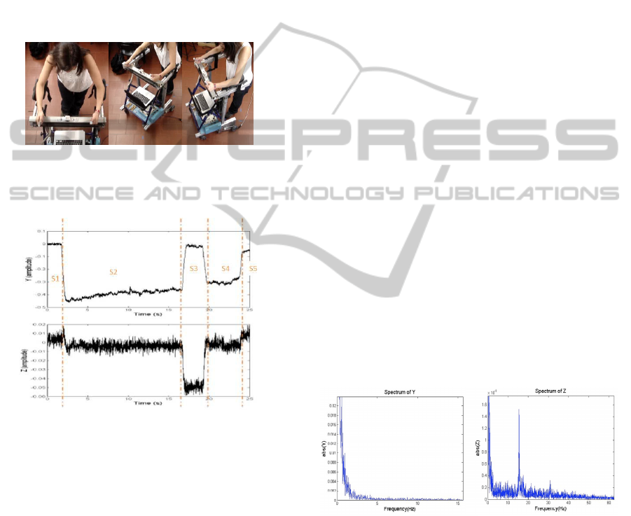
the other.When the user turns right (S3), the joystick
is made to move around the Z-axis to the right side
also, presenting a negative Z-signal. At the same
time, in the Y-axis the joystick tends to go to rest,
presenting a zero Y-signal. The next step is to move
forward (S4), and the Z-signal returns to zero while
the Y-signal becomes negative. At the end of the
trajectory, the user stops (S5), and the Y-signal
returns to zero. Z-signal remains in zero.
In the case that the user wants to turn right, the
only difference is that the Z-signal becomes positive
instead negative.
a) b) c)
Figure 2: a) Walking forward, b) turning right and c)
turning left.
Figure 3: Typical raw Y and Z joystick data in the
NeoASAS walker when the user is performing the
following trajectory: S1- The user is stopped; S2- User
starts walking forward; S3- User turns right; S4- User
walks forward; S5 – User stops.
Now, one can conclude that the joystick system
read correctly the user’s command intentions.
However, by observing the characteristics of the
signals Z and Y, it can be identified two main
components of the signals. One component (i)
represents the highest frequency noise caused by the
vibrations of the structure. This component must be
eliminated in real-time. For that, it will be used a
filter which choice will be presented in detail on the
next section. The other component (ii) contains the
information of the walking movement intentions of
the user to guide the walker. This signal will enable
the development of robust and secure control
strategies.
3 FILTERING STRATEGY
The filtering strategy aims to eliminate in real-time
the component (i).
The data that was collected yields that the user’s
commands intentions occur in a frequency range
between 0 and 2 Hz in both Y and Z-signals, and the
higher-frequency components are related to noise. In
figure 4, one can see the spectrum for typical Y and
Z-signals. The Z-signal has more accentuated
higher-frequencies than the Y-signal.
The higher frequency components present in the
signals can be eliminated with forth and back
recursive digital filters, such as Butterworth filters,
without causing phase distortion. However, this
approach is not real-time implementable. As this
technique is not suitable for real-time applications,
this filter will be set as a basis to evaluate the
performance of the chosen filter strategy.
Besides this, the user should not perceive the
delay between his commands and the movement of
the walker. The human perception threshold in
applications like this is known to be around the 200
ms.
In the literature, two types of filters were
identified: g-h filter (Benedict-Bordner and
Critically Damped) and the Kalman filter, and they
are usually called as tracking filter (E.Brookner,
1998).
Figure 4: Example of a Frequency Spectrum for (left) raw
Y-signal and (right) raw Z-signal.
3.1 User’s Movement Intentions
Tracking Filters
g-h filter In this filter measurements are used to
correct the predictions that are made for the signal,
minimizing the estimation error. Formulation is
presented in (Brookner, 1998). This filter presents
two parameters (g,h) that need to be offline tuned.
To this, the Benedict-Bordner Filter (BBF), equation
ICINCO2012-9thInternationalConferenceonInformaticsinControl,AutomationandRobotics
460

(1), and the Critically Damped Filter (CDF),
equation (2) will be applied to select the filter
parameters.
h =
g
2
2 − g
(1)
This equation relates g and h, such that the BBF has
one degree of freedom. In g-h filters increasing the
value of g diminishes the transient error. Thus, a
larger g makes the BBF to track higher frequencies.
The (CDF) minimizes the least squares fitting
line of previous measurements, giving old data
lesser significance when forming the total error sum.
This is achieved with a weight factor θ. Parameters
in the g–h filter are related by:
2
2
)1(
1
θ
θ
−=
−=
h
g
(2)
Kalman Filter here depicted is the conventional
Kalman filter and is only suitable for linear systems
(E.Brookner., 1998).
Therefore, state vector x(t) is composed by the
variable to be estimated, and its derivative. In the
current problem, is considered the system dynamic
equations:
1
1
,
kkk
kkk
x
xTx
x
xu
+
+
=+
=+
&
&&
(3)
In these equations it is presented a stochastic model
that considers a first derivative influenced by a
random noise
u
k
, i.e. first derivative is not constant.
The equation that links the actual state
x
k
and
the measured y
k
is called the observation equation:
kkk
vxy
+
=
(4)
Where v
k
is the process noise.
The Kalman filter parameters will be the
measurement noise covariance R and the process
noise covariance Q.
In the implementation of the filter, the
measurement noise covariance R is measured prior
to operation of the filter. Measuring the
measurement error covariance R is practical because
generally it is simple to take some off-line sample
measurements in order to determine the average
variance of the measurement noise:
[
]
.
2
x
R
σ
=
Its
value is 8.82x10
-5
rad
2
.s
-2
for the Y-signal noise and
1.3x10
-5
rad
2
.s
-2
for the Z-signal noise.
The selection of the process noise covariance Q
is formulated based on the first derivative noise,
which affects the estimation of the user’s command
intentions. The value of Q is related to the process
error of the system. Thus, a good choice of Q helps
the filter to estimate more precisely the true state.
It is calculated using of-line measures of the
signal. For each measure the covariance of the signal
is calculated. Finally, the process noise covariance is
the average of all the calculated covariance.
3.2 Evaluation of User’s Movement
Intentions Trackers Filters
The selection of the BBF parameter g, CDF
parameter θ and Kalman filter parameter Q, is
presented in this section.
For this selection the Kinematic Estimation Error
(KTE) was used. KTE evaluates the smoothness,
response time, and execution time of a tracking
algorithm (E.Rocón, 2010) and is expressed by:
2
2
σε
+=KTE
(5)
and σ
2
are the mean and variance of the
absolute estimation error between a desired signal
and the measured signal. The desired signal is
obtained by filtering offline the signals’
measurements with a Butterworth filter.
To select the filters parameters (g, θ and Q), 11
individuals drove the walker without any
motorization executing three different trajectories
with five repetitions each. During these experiments
the signals of the joystick were acquired.
These signals were then introduced off-line in
the 3 filters algorithm using a broad range of g, θ
and Q parameters. The result was processed by the
KTE. The best solutions for each filter, i.e. the ones
with the lowest KTE, were chosen for each user,
experiment and repetition. With these results, it was
calculated the mean of the best 165 solutions for
each parameter, as well as the mean of the delay
between the input and the output for each case.
Table 1 and 2 present the mean values of the best
solutions of g, θ and Q parameters, delay between
the original joystick signal (Y and Z) and the filtered
one and KTE for each joystick signal (Y and Z).
Table 1: Filter Parameters based on the KTE and delay for
the Y-signal. Table provides for mean±standard deviation.
Value KTE (x10
-3
rad/s) Delay (ms)
g 44.20±4.97(x10
-3
) 6.46±0.91 0.5±0.25
θ 0.974±3.85x10
-3
6.81±0.75 1.7±0.96
Q 3.21±0.55(.10
-7
) 9.66±0.86 17.2±1.86
SmartWalkerControlthroughtheInferenceoftheUser'sCommandIntentions
461
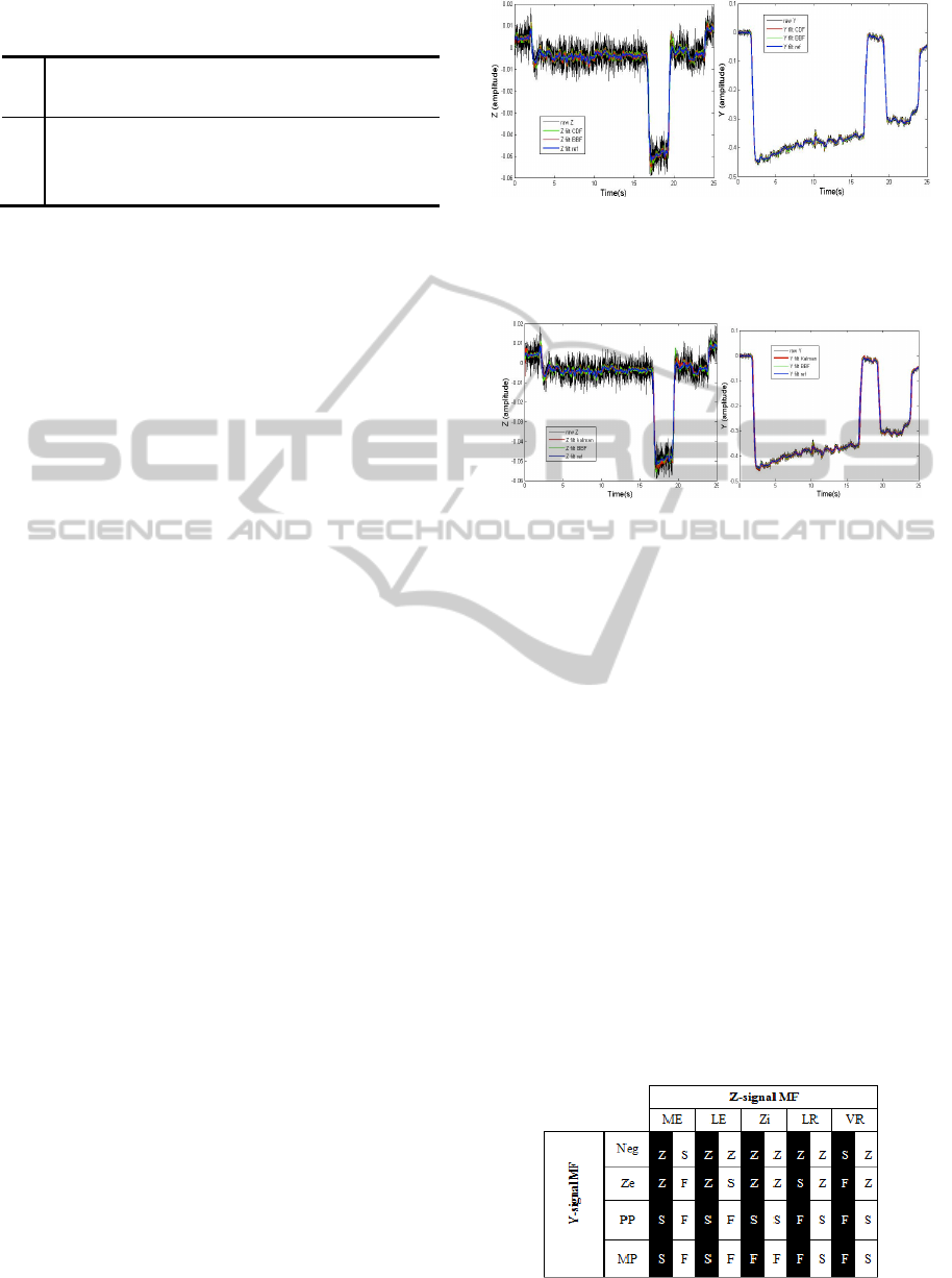
Table 2: Filter Parameters based on the KTE and delay for
the Z-signal. Table provides for mean±standard deviation.
Value
KTE (x10
-3
rad/s)
Delay
(ms)
g 16.87±2.51(x10
-3
) 2.93±1.99 23.8±1.70
θ 0.990±1.1x10
-3
2.99±0.11 25.2±1.59
Q 3.26x10
-9
±8.78(.10
-9
) 3.12±0.26 36.2±4.00
As it can be seen in Table 1 and 2, g of the Z-
signal compared with the g parameter of the Y-
signal shows a lower value. Similarly, the average θ
and Q parameters of the Z-signal compared with the
average θ and Q parameters of the Y-signal shows a
higher value. These results were as expected, since
Z-signal required being further filtered.
All filters are of high quality for a human-
machine interaction because the introduced delay is
much more inferior to human perception (200 ms),
not causing prejudice to the human-machine
interaction.
KTE is very low for all filters, being the lowest
one, the BBF’s KTE value, as well as its dispersion.
Additionally, the BBF detains the lowest signals’
delay.
Since BBF presents the lowest KTE for both
signals, one can conclude that it is the best option to
choose for this application.
This can also be seen in an example of joystick
signal in figure 5, where is presented the differences
between BBF and CDF; and figure 6 presents the
differences between BBF and Kalman, as well as the
reference. The BBF shows a higher attenuation on
the oscillations than the CDF and Kalman filters.
Thus, a Benedict-Bordner g-h filter was applied
to the joystick data. The g parameter was chosen to
be 44.29x10
-3
for the Y-signal and 16.87x10
-3
for the
Z-signal. Thus filter has a low computational cost
algorithm, making it a good option to this
application, since it can run in a low cost hardware
with enough robustness for a commercial device.
4 CONTROL STRATEGY
In this section, it is addressed a control strategy
based on fuzzy logic to classify the signals sent by
the joystick and transform them into motor outputs
(direction and velocity), in such way that the walker
drives the motors according to the user’s commands.
The two fuzzy logic inputs will be the Y and Z-
signal.
Figure 5: (left) The superposition of the raw Z with the
results of BBF, CDF and Butterworth; (Right) The
superposition of the raw Y with the results of BBF, CDF
and Butterworth.
Figure 6: (Left) superposition of the raw Z with the results
of BBF, Kalman and Butterworth; (Right) superposition of
the raw Y with the results of BBF, Kalman and
Butterworth.
It was defined a set of membership functions
(MF) for each joystick signal and they were
constituted by Gaussian and bell functions. The variables,
which form the set of MF for the Z-signal and that will
interpret this signal, are divided onto: much left (ME),
little left (LE), zero (Zi), little right (LR) and much right
(VR). Similarly, the variables, which form the set of MF
for the Y-signal and that will interpret this signal, are
divided into: negative (Neg), zero (Ze), little positive (PP)
and very positive (MP). For the motors right (MR) and left
(ML), the output MF set is divided onto: zero (Z), slow (S)
and fast (F).The decision-making rules are presented in
Table 3.
A series of experiments with motorization were
conducted to assess the functioning of the fuzzy
system and allow the tuning of the parameters of the
implemented system.
Table 3: Decision-making rules. Black (white) columns
are related to the left (right) motor.
ICINCO2012-9thInternationalConferenceonInformaticsinControl,AutomationandRobotics
462
5 VALIDATION OF THE
PURPOSED ARCHITECTURE
WITH HEALTHY USERS.
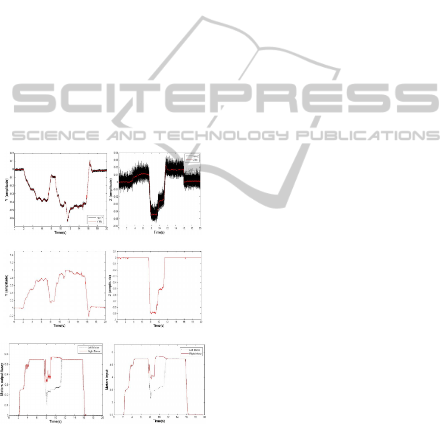
In figure 7, an example of results is shown. The
signals were acquired while a user was performing
the following trajectory: Start to walk, walk forward,
turn left, walk forward and stop. Figure 7 a) shows
that with the addition of the motors in the movement
of the walker, the Y and Z-signals present a more
accentuated noise, comparing with the one saw in
figure 3. However, the results from the filter BBF
are very satisfactory in attenuating the noise
components.
In figure 7 b) it is shown the result obtained
before the BBF filter, as well as an adjustment on
the gains of the signals. The Y and Z-signal were
inverted, amplified and are in the range of [-1,1].
In figure 7 c) the outputs of the fuzzy control
system were smoothed and converted to the range of
[2.5,5] in order to be sent to the low-level control
hardware to command the DC motors.
a)
b)
c)
Figure 7: Results from the system architecture of the
NeoASAS walker. a) raw acquired joystick signals and the
result from the filtering with the BBF filter; b) signals
before and after the amplification and restrictions; c)
output of the fuzzy system (left) and their integration to
then be sent to the control board hardware (right).
Despite the variations of the Y and Z-signal, the
motors present a constant and safe movement.
Therefore, the system is perfectly adjusted to read
the user’s command intentions.
Thus, it was successfully generated a control
strategy which has low computational cost, allowing
a smooth and enjoyable driving, fast response of the
walker and no sense of delay.
6 CONCLUSIONS
In this work it was presented a method of user-
walker interaction to extract the users’ command
intentions. A series of experiments using with
healthy users were performed which showed the
sensibility of the joystick to extract navigation
commands from the user. The proposed control
strategy showed very good results, allowing a
smooth and enjoyable driving, fast response of the
walker and no sense of delay.
ACKNOWLEDGEMENTS
This work is financiered by FEDER Funds and
through Programa Operacional Fatores de
Competitividade – COMPETE and by National
Funds through FCT - Fundação para a Ciência e
Tecnologia under the Project: FCOMP-01-0124-
FEDER-022674.
Work supported by Portuguese Science
Foundation (grant SFRH/BD/76097/2011).
REFERENCES
Martins, M., Frizera, A., Santos, C., Ceres, R., (2011).
Assistive Mobility Devices focusing on Smart
Walkers: Classification and Review. Robotics and
Autonomous Systems. DOI: 10.1016/j.robot.2011.11.
015.
Frizera, A., Gallego, J., Rocon, E., Pons, J., Ceres, R.,
(2010). Extraction of userʼs navigation commands
from upper body force interaction in walker assisted
gait. BioMedical Engineering Online, 9(37), 1-16.
Lee, G., Ohnuma, T., Chong, N., (2010). Design and
control of JAIST active robotic walker. Intel Serv
Robotics.
Brookner, E., (1998). Tracking and Kalman Filtering
Made Easy. John Wiley & Sons, Inc.
Rocón, E., Ruiz, J., Moreno, J., Pons, J., Miranda, A.,
(2010). Tremor Characterization: Algorithms for the
study of tremor time series. Sensors.
SmartWalkerControlthroughtheInferenceoftheUser'sCommandIntentions
463
