
Improvement of Extraction Method for Inter-turn Fault Detection in
IPMSM under Transient Conditions
Gyu Tae Choi
1
, Je Won Lee
1
, Minho Choi
2
and Sang Woo Kim
1,2
1
Department of Electrical Engineering, POSTECH, Pohang, Korea
2
Department of Creative IT Excellence Engineering and Future IT Innovation Laboratory, POSTECH, Pohang, Korea
Keywords:
Extracting Non-stationary Sinusoids, Inter-turn Faults, Interior Permanent Magnet Synchronous Motor
(IPMSM), Motor Current Signature Analysis (MCSA).
Abstract:
Most fault detection techniques are focused on induction motors and are based on steady-state conditions. In
this paper, an extraction method for inter-turn fault detection in interior permanent magnet synchronous motors
(IPMSM) is proposed. The study is focused on an IPMSM under non-stationary conditions. The technique is
formulated by modifying existing fixed frequency sinusoid tracking algorithms, which is based on an adaptive
algorithm for extracting non-stationary sinusoids. The faults are determined using the motor current signature
analysis technique. Simulations performed in this study validate that the proposed algorithm improves the
extraction performance.
1 INTRODUCTION
As the depletion of natural resources has increased
over the years, the electric vehicle industry faces the
challenge of solving the problem of this depletion. In
particular, the motor is a component that directly af-
fects the safety of the vehicle driver. It is important to
detect faults in a motor using nondestructive inspec-
tion. Until now, most research has been focused on in-
duction motors (Seera et al, 2012). However, the per-
manent magnet synchronous motor (PMSM) and inte-
rior permanent magnet synchronous motor (IPMSM)
are used in electric vehicles because of their high ef-
ficiency and high power, among other qualities. Fur-
thermore, IPMSM is more durable than PMSM.
In (Gandhi et al, 2011), a review of existing tech-
niques available for on-line stator inter-turn fault de-
tection and diagnosis in electrical machines was pre-
sented. Recent techniques that have been used to
detect faults are based on signal analysis, models,
or knowledge-based systems. The first method used
to detect faults is signal analysis. Signal analysis
techniques include the fast Fourier transform (FFT),
short-time Fourier transform(STFT), wavelet trans-
form(WT), and adaptive algorithms. It is difficult to
accurately perform an FFT on the stator current be-
cause of problems such as frequency resolution, mag-
nitude accuracy at steady state, and more generally,
data processing. The STFT and WT were proposed
to overcome these drawbacks (Cusido et al, 2008).
However, it is difficult to detect faults because of the
high computational complexity. The second method
used to detect faults is the model-based fault detection
method (Vaseghi et al, 2008). In the case of IPMSMs,
this method has difficulty to establishing a model be-
cause of asymmetric inductance (an inductance of d
axis, L
d
, is not the same as an inductance of q axis,
L
q
). The third method to detect faults is based on
knowledge-based systems such as neurofuzzy logic
or neural networks (Ayhan et al, 2006). These strate-
gies should be considered when a specific industrial-
condition-monitoring device needs to be implemented
to reduce the misinterpretation of the signatures that
are obscured by factors such as measurement noises
and differing load conditions (Ayhan et al, 2006). In a
previous paper (Barendse and Pillay, 2006), without a
low pass filter, a cascaded structure was proposed for
a single fixed frequency sinusoid tracking algorithm.
2 FAULTS AND DETECTION
METHOD
2.1 Inter-turn Faults
Inter-turn faults are caused by the breakdown of turn-
to-turn insulation as a result of the voltage, current,
427
Choi G., Lee J., Choi M. and Kim S..
Improvement of Extraction Method for Inter-turn Fault Detection in IPMSM under Transient Conditions.
DOI: 10.5220/0004029704270430
In Proceedings of the 9th International Conference on Informatics in Control, Automation and Robotics (ICINCO-2012), pages 427-430
ISBN: 978-989-8565-22-8
Copyright
c
2012 SCITEPRESS (Science and Technology Publications, Lda.)

or thermal stress acting on the stator winding. This
type of fault is responsible for one quarter of all faults.
This fault can rapidly propagate to other stator turns
because it creates a large circulating current in the
shorted path. Since the magnitude of the second-
order harmonics in the q-axis current is proportional
to the number of shorted turns and operating speed,
the fault becomes considerably large as the number
of shorted turns and the magnitude of speed increases
(Kim, 2011). Consequently, other faults such as ec-
centricity faults, open circuit faults, and demagneti-
zation faults are generated by the inter-turn faults. It
is necessary to detect inter-turn faults immediately be-
cause of these dangers. The early detection of stator
winding failures is important in order to avoid greater
risk to the drive.
2.2 Motor Current Signature Analysis
(MCSA)
Motor current signature analysis (MCSA) analyzes
the amplitudes of the harmonics of the stator cur-
rent. When the amplitude is over a threshold value,
which is denoted by the standard amplitude of a nor-
mal current, an inter-turn fault is detected. MCSA
has proven to be an efficient technique for fault de-
tection and is the most popular technique (Gandhi et
al, 2011). In order to detect inter-turn faults, it is im-
portant to determine their frequencies. As shown in
(Sottile, 2001), the faulty harmonics are located at
f
f ault
= 3 × f
f und
where f
f ault
is the frequency component associated
with inter-coil shorts within the stator winding, and
f
f und
is the stator fundamental frequency. This
means that the frequency component associated with
an inter-turn fault depends on the fundamental fre-
quency. As the speed of a vehicle increases or de-
creases, the vehicle is in a transient state. In a tran-
sient state, the fundamental frequency should vary
with the vehicle speed. Thus, the frequency of the
faults should change proportionally. Hence, an ex-
traction algorithm under transient conditions through
MCSA is required.
2.3 Description of Overall System
The block diagram of the overall detection system is
shown in Fig. 1. In an electric vehicle, the battery
is used to power the motor, which is an IPMSM. The
battery has a voltage of approximately 15V. Because
the output of the battery is DC, an inverter should
be used to convert DC to AC. The output of the in-
verter consequently becomes AC, which powers the
Battery
DC-AC
Inverter
IPMSM
Motor
Controller
Low Pass
Filter
Fault
Detection
Algorithm
Fault
Classification
Fault
Indicator
I(t)
,
Figure 1: Block diagram of motor drive and fault detection
strategy.
IPMSM. To control the speed of the IPMSM, the mo-
tor controller receives the angle and angular velocity
of the IPMSM and the angle of the rotor from the re-
solver. The input current of the IPMSM is the target
signal that is extracted to detect faults. The input cur-
rent is passed through a low pass filter and then used
in the fault detection algorithm. The algorithm ex-
tracts the input signal and classifies each harmonic. It
is impossible to classify the harmonics from the entire
signal that is received from the current sensor. Using
fault equations (Barendse and Pillay, 2006), the fre-
quencies of the faults are determined. Subsequently,
the fault indicator indicates the faulty signal to the ve-
hicle control unit. The significant harmonic compo-
nents are identified by the fault detection algorithm.
3 PROPOSED ALGORITHM
3.1 Theoretical Background
In this section, the adaptive algorithm is introduced
along with a description of how the algorithm is
adapted in a conventional algorithm to extract the in-
put current signal. The adaptive algorithm shows re-
markable qualities in tracking and extracting the non-
stationary sinusoid, while minimizing the square er-
ror. Let i(t) denote a stator current signal
i(t) = i
c
(t) + i
n
(t)
where i
c
(t) is the pure current signal, and i
n
(t) is the
noise component. i
c
(t) can be represented in detail as
follows;
i
c
(t) = I
c
sin(
Z
ω(τ)dτ + δ)
where I
c
is the amplitude of the current, ω is the vary-
ing angular velocity dependent on time, and δ is the
angle shift. Let i
out
denote the output current esti-
mated by the adaptive algorithm.
i
out
= i
f und
+ i
1
+ i
2
+ .. (1)
ICINCO 2012 - 9th International Conference on Informatics in Control, Automation and Robotics
428

where i
f und
is the component of the current at the fun-
damental frequency, and i
1
, i
2
, ... are the harmonic
components.
i
f und
(t) = A(t)sin(
Z
ω(τ)dτ + δ) (2)
Let φ(t)=
R
ω(τ)dτ + δ. The conventional algorithm is
updated in detail as follows;
dA(t)
dt
= µ
1
e(t)sin(φ(t)) (3)
dω(t)
dt
= µ
2
e(t)cos(φ(t)) (4)
dφ(t)
dt
= µ
2
µ
3
e(t)cos(φ(t)) + ω(t) (5)
e(t) = i(t) − i
f und
(6)
e
1
(t) = i(t) − i
f und
(t) − i
1
(t) (7)
The parameters µ
1
, µ
2
, and µ
3
are positive constants
that regulates the algorithm. The values of the pa-
rameters control the convergence rate as well as the
stability of the algorithm. The least squares error be-
tween input signal i(t) and the estimated sinusoidal
signal i
f und
(t) is minimized by the use of the gradient
descent method (Ziarani and Konrad, 2004).
3.2 Proposed Algorithm
Fig. 2 shows the conventional algorithm (Barendse
and Pillay, 2006). However, it is difficult to detect har-
Amplitude
Calculation
X
Frequency
Calculation
X
Cosine
Sine
i(t)+ e(t)
I(t)
()t
Ifund(t)
()t
Amplitude
Calculation
X
Frequency
Calculation
X
Cosine
Sine
()t
()t
I(t)
+
-
Fault Equation
()
fault
t
-
e(t)
I1(t)
e1(t)
Figure 2: Block diagram of conventional algorithm.
monics accurately because (6) is used as the first step
to detect i
f und
. This means that the harmonics are also
used to detect i
f und
. The conventional algorithm does
not guarantee the detection of the frequency compo-
nents associated with the fault. To solve this problem,
the proposed algorithm uses (8) to extract fundamen-
tal components in detail as follows;
e(t) = i(t) − i
f und
(t) − i
1
(t) (8)
Further, the error in the harmonics is also used to up-
date the algorithm using (8). As the rpm of the electric
vehicle is limited from 0 rpm to 8000 rpm, the funda-
mental frequency of the IPMSM is also limited about
0 Hz to 500 Hz generally. It means that harmonic
components of the high frequency don’t need to ex-
tract to detect the inter-turn fault. Therefore, a low
pass filter is established to improve extracting perfor-
mance. Fig. 3 shows the proposed algorithm. The
amplitude and frequency are calculated by (3) and (4),
respectively. Then, each component is updated using
(8).
Amplitude
Calculation
X
Frequency
Calculation
X
Cosine
Sine
i(t)+ e(t)
I(t)
()t
Ifund(t)
()t
Amplitude
Calculation
X
Frequency
Calculation
X
Cosine
Sine
()t
()t
I(t)
I1(t)
+
+
Fault Equation
()
fault
t
-
Figure 3: Block diagram of proposed algorithm.
4 SIMULATION RESULTS
To test the performance of the algorithm, a sinusoidal
input current is created in a MATLAB simulation.
The i
n
(t) is added with white Gaussian noise. The
frequency of the single-phase stator current is calcu-
lated from the rotor speed (rpm), which is varied from
400 rpm to 600 rpm over 0.75 s under no load condi-
tions (Barendse and Pillay, 2006). If we assume that
the IPMSM has four pole pairs, the frequency is cal-
culated using the following equation :
f requency =
rpm × pole pairs
60
(9)
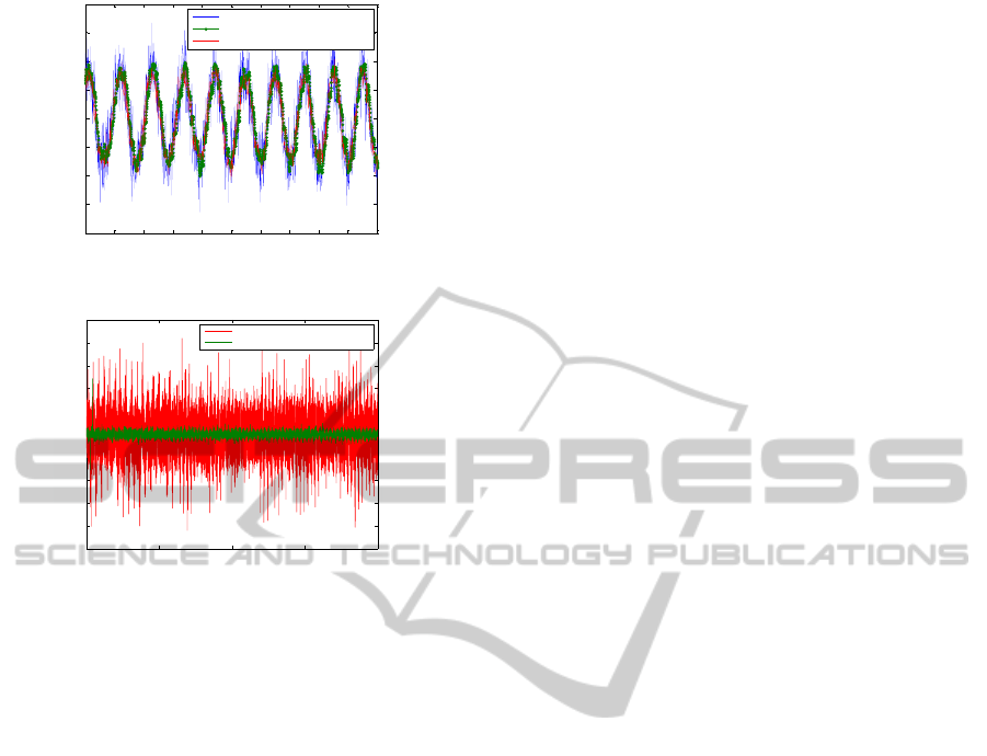
Fig. 5 shows that the input current is a sinusoidal
waveform with a non-stationary frequency and also
shows that the output current of the proposed algo-
rithm and the conventional algorithm. The cutoff fre-
quency of the low pass filter is set at 300 Hz and the
sampling frequency is set at 10 kHz using the MAT-
LAB toolbox. The values of the parameters µ
1
, µ
2
,
and µ
3
are set at 500, 50000, 0.02, respectively. The
values of the step sizes is also applied to conventional
algorithm compared with proposed algorithm. These
results show that the output current resembles the ex-
tracted input current. Fig. 6 shows the error, which
is the difference between the input current and the
output current. The results show that the proposed
algorithm outperforms the conventional algorithm at
extraction.
Improvement of Extraction Method for Inter-turn Fault Detection in IPMSM under Transient Conditions
429
0.8 0.82 0.84 0.86 0.88 0.9 0.92 0.94 0.96 0.98 1
-20
-15
-10
-5
0
5
10
15
20
Time(s)
Current(A)
Input current
Output current of proposed algorithm
Output current of convention algorithm
Figure 4: Test input signal and output signal.
0 0.5 1 1.5 2
−25
−20
−15
−10
−5
0
5
10
15
20
25
Error current(A)
Time(s)
Error of the conventional algorithm
Error of the proposed algorithm
Figure 5: Difference signal from input and output.
5 CONCLUSIONS
This paper focuses on a fault detection algorithm. By
using the proposed update error and the low pass fil-
ter, the extraction performance is improved. The pro-
posed technique is tested using the MATLAB simu-
lation. The test results show that the proposed tech-
nique is able to reduce the difference between the ref-
erence current signal and the extracted current signal.
Because the high accuracy is required to detect inter-
turn fault under non-stationary operating conditions
the proposed fault detection algorithm is more suit-
able for identifying faults.
ACKNOWLEDGEMENTS
”This research was supported by the MKE(The Min-
istry of Knowledge Economy), Korea, under the
ITRC(Information Technology Research Center) sup-
port program (NIPA-2012-H0301-12-2002) super-
vised by the NIPA(National IT Industry Promotion
Agency)”
”This research was supported by the MKE(The
Ministry of Knowledge Economy), Korea, under the
IT Consilience Creative Program support program su-
pervised by the NIPA(National IT Industry Promotion
Agency)” (C1515-1121-0003)
REFERENCES
M. Seera, C. P. Lim, D. Ishak, H. Singh (2012). Fault Detec-
tion and Diagnosis of Induction Motors Using Motor
Current Signature Analysis and a Hybrid FMMCART
Model. In IEEE Transactions on Neural Networks and
Learning Systems.
A. Gandhi, T. Corrigan, L. Parsa (2011). Recent Advances
in Modeling and Online Detection of Stator Interturn
Faults in Electrical Motors. In IEEE Transactions on
Industrial Electronics.
J. Cusido,L. Romeral,J. Ortega, J. Rosero and A. G. Es-
pinosa (2008). Fault Detection in Induction Machines
Using Power Spectral Density in Wavelet Decomposi-
tion. In IEEE Transactions on Industrial Electronics.
B. Vaseghi, B. N. Mobarekeh, N. Takorabet, F. M. Tabar
(2008). Experimentally Validated Dynamic Fault
Model for PMSM with Stator Winding Inter-Turn
Fault. In Industry Applications Society Annual Meet-
ing.
B. Ayhan, M. Y. Chow, M. H. Song (2006). Multiple dis-
criminant analysis and neural-network-based mono-
lith and partition fault-detection schemes for broken
rotor bar in induction motors. In IEEE Trans. Ind.
Electron.
P. S. Barendse and P. Pillay (2006). A new algorithm for the
detection of faults in permanent magnet machines. In
IEEE Industrial Electronics, IECON.
J. H. Kim (2011). Simple Online Fault Detecting Scheme
for Short-Circuited Turn in a PMSM Through Current
Harmonic Monitoring. In IEEE Transactions on In-
dustrial Electronics.
J. Sottile, F. C. Trutt and A. W. Leedy (2001). ‘Condition
monitoring of brushless three-phase synchronous gen-
erators with stator winding or rotor circuit deteriora-
tion. In Applications Conference, 2001. 36th IAS An-
nual Meeting.
A. K. Ziarani, A. Konrad(2004). A methodof extraction of
non-stationary sinusoids. In ignal Processing.
ICINCO 2012 - 9th International Conference on Informatics in Control, Automation and Robotics
430
